EP0104086B1 - Dispositif et procédé pour l'alimentation et la séparation de feuilles - Google Patents
Dispositif et procédé pour l'alimentation et la séparation de feuilles Download PDFInfo
- Publication number
- EP0104086B1 EP0104086B1 EP19830305561 EP83305561A EP0104086B1 EP 0104086 B1 EP0104086 B1 EP 0104086B1 EP 19830305561 EP19830305561 EP 19830305561 EP 83305561 A EP83305561 A EP 83305561A EP 0104086 B1 EP0104086 B1 EP 0104086B1
- Authority
- EP
- European Patent Office
- Prior art keywords
- stack
- sheet
- retard
- sheets
- normal force
- Prior art date
- Legal status (The legal status is an assumption and is not a legal conclusion. Google has not performed a legal analysis and makes no representation as to the accuracy of the status listed.)
- Expired
Links
- 238000000034 method Methods 0.000 title claims description 6
- 230000007423 decrease Effects 0.000 claims description 4
- 230000004044 response Effects 0.000 claims description 4
- 239000000843 powder Substances 0.000 description 9
- 238000012546 transfer Methods 0.000 description 9
- 230000007246 mechanism Effects 0.000 description 6
- 238000000926 separation method Methods 0.000 description 5
- 238000013459 approach Methods 0.000 description 4
- 239000002245 particle Substances 0.000 description 4
- 230000032258 transport Effects 0.000 description 4
- 230000008859 change Effects 0.000 description 3
- 238000004140 cleaning Methods 0.000 description 3
- 238000003384 imaging method Methods 0.000 description 3
- 239000000463 material Substances 0.000 description 3
- 238000012545 processing Methods 0.000 description 3
- 241000234282 Allium Species 0.000 description 2
- 235000002732 Allium cepa var. cepa Nutrition 0.000 description 2
- 230000009471 action Effects 0.000 description 2
- 230000006835 compression Effects 0.000 description 2
- 238000007906 compression Methods 0.000 description 2
- 238000011161 development Methods 0.000 description 2
- 230000009977 dual effect Effects 0.000 description 2
- 238000006424 Flood reaction Methods 0.000 description 1
- 241000237858 Gastropoda Species 0.000 description 1
- 229910001370 Se alloy Inorganic materials 0.000 description 1
- BUGBHKTXTAQXES-UHFFFAOYSA-N Selenium Chemical class [Se] BUGBHKTXTAQXES-UHFFFAOYSA-N 0.000 description 1
- 238000005452 bending Methods 0.000 description 1
- 230000008878 coupling Effects 0.000 description 1
- 238000010168 coupling process Methods 0.000 description 1
- 238000005859 coupling reaction Methods 0.000 description 1
- 230000000694 effects Effects 0.000 description 1
- 239000008187 granular material Substances 0.000 description 1
- 150000002500 ions Chemical class 0.000 description 1
- 238000012986 modification Methods 0.000 description 1
- 230000004048 modification Effects 0.000 description 1
- 230000007935 neutral effect Effects 0.000 description 1
- 230000003287 optical effect Effects 0.000 description 1
- 230000009467 reduction Effects 0.000 description 1
- 238000012552 review Methods 0.000 description 1
- 239000007921 spray Substances 0.000 description 1
- 230000003068 static effect Effects 0.000 description 1
- 239000000758 substrate Substances 0.000 description 1
Images


Classifications
-
- G—PHYSICS
- G03—PHOTOGRAPHY; CINEMATOGRAPHY; ANALOGOUS TECHNIQUES USING WAVES OTHER THAN OPTICAL WAVES; ELECTROGRAPHY; HOLOGRAPHY
- G03G—ELECTROGRAPHY; ELECTROPHOTOGRAPHY; MAGNETOGRAPHY
- G03G15/00—Apparatus for electrographic processes using a charge pattern
- G03G15/65—Apparatus which relate to the handling of copy material
- G03G15/6529—Transporting
-
- B—PERFORMING OPERATIONS; TRANSPORTING
- B65—CONVEYING; PACKING; STORING; HANDLING THIN OR FILAMENTARY MATERIAL
- B65H—HANDLING THIN OR FILAMENTARY MATERIAL, e.g. SHEETS, WEBS, CABLES
- B65H7/00—Controlling article feeding, separating, pile-advancing, or associated apparatus, to take account of incorrect feeding, absence of articles, or presence of faulty articles
- B65H7/02—Controlling article feeding, separating, pile-advancing, or associated apparatus, to take account of incorrect feeding, absence of articles, or presence of faulty articles by feelers or detectors
- B65H7/06—Controlling article feeding, separating, pile-advancing, or associated apparatus, to take account of incorrect feeding, absence of articles, or presence of faulty articles by feelers or detectors responsive to presence of faulty articles or incorrect separation or feed
- B65H7/12—Controlling article feeding, separating, pile-advancing, or associated apparatus, to take account of incorrect feeding, absence of articles, or presence of faulty articles by feelers or detectors responsive to presence of faulty articles or incorrect separation or feed responsive to double feed or separation
- B65H7/125—Controlling article feeding, separating, pile-advancing, or associated apparatus, to take account of incorrect feeding, absence of articles, or presence of faulty articles by feelers or detectors responsive to presence of faulty articles or incorrect separation or feed responsive to double feed or separation sensing the double feed or separation without contacting the articles
-
- B—PERFORMING OPERATIONS; TRANSPORTING
- B65—CONVEYING; PACKING; STORING; HANDLING THIN OR FILAMENTARY MATERIAL
- B65H—HANDLING THIN OR FILAMENTARY MATERIAL, e.g. SHEETS, WEBS, CABLES
- B65H2601/00—Problem to be solved or advantage achieved
- B65H2601/20—Avoiding or preventing undesirable effects
- B65H2601/25—Damages to handled material
Definitions
- This invention relates to a sheet feeding and separating apparatus and method for feeding individual sheets from a stack and more particularly to such apparatus and methods that employs stack force relief or enhancement in order to feed a wide latitude of sheets.
- a major problem associated with sheet feed devices is in feeding papers of varying weights, curl conditions and surface characteristics.
- sheet feed devices are designed specifically for a particular type or weight of paper having known characteristics.
- the sheet feeders are usually designed specifically for a certain copy paper characteristic.
- the machine will be exposed to a wide variety of sheets ranging from extremely heavy paper (50 kg (110 lb.) card stock) all the way to onion skin (4 or 3.6 Kg (9 lb. or 8 Ib.) ⁇ bond).
- a feeder is designed to handle the lightest weight paper that may be encountered, in all probability it will not feed heavy stock paper reliably. At the other extreme, if a feeder is designed to handle heavy weight paper there is a possibility that the feeder would severely mutilate light weight paper such as onion skin.
- US-A-4,171,130 discloses an article feeding device in which the contact pressure of a feeding member is automatically maintained by a control circuit.
- a structural arrangement is shown in US ⁇ A ⁇ 3,981,493 that includes a sensor located between a mechanism that feeds articles from a stack and a mechanism that forwards the articles for further processing. The sensor which is connected to a control circuit controls the operation of the feeding mechanism.
- Ricoh publication JP-A 53-34522 (US-A-4124276) shows a sheet feeding device that includes reducing the normal force on a stack of sheets in order to decrease multifeeds.
- the present invention as defined in the appended claims overcomes the above-mentioned difficulties by employing a retard feeder and separator apparatus that senses the threat of a misfeed or multifeed and adjusts the stack normal force of a feed member against a stack of sheets.
- a preferred feature of the present invention is to provide a feed means and retard separator that is mounted on a movable frame and located downstream from a sheet feeding area.
- a sensor detects the lead edge of a sheet fed from a stack as it reaches the retard nip and causes an actuator connected to the frame to pull against the frame and thereby rebalance the feed means.
- the stack normal force is thereby reduced while the sheet continues to be fed from the stack by the force in the retard nip and by the lower value of stack normal force.
- the sensor does not sense a sheet by a predetermined time, the stack normal force will be maintained at the high level.
- FIG. 1 schematically depicts the various components of an illustrative electrophotographic printing machine incorporating the sheet feeding and separating apparatus of the present invention therein.
- the illustrative electrophotographic printing machine employs a belt 10 having a photoconductive surface thereon.
- the photoconductive surface is made from a selenium alloy.
- Belt 10 moves in the direction of arrow 12 to advance successive portions of the photoconductive surface through the various processing stations disposed about the path of movement thereof.
- a corona generating device indicated generally by the reference numeral 14, charges the photoconductive surface to a relatively high substantially uniform potential.
- a document handling unit indicated generally by the reference numeral 15, positions original document 16 facedown over exposure system 17.
- the exposure system indicated generally by reference numeral 17 includes lamp 20 which illuminates document 16 positioned on transparent platen 18.
- the light rays reflected from document 16 are transmitted through lens 22.
- Lens 22 focuses the light image of original document 16 onto the charged portion of the photoconductive surface of belt 10 to selectively dissipate the charge thereof. This records an electrostatic latent image on the photoconductive surface which corresponds to the informational areas contained within the original document.
- belt 10 advances the electrostatic latent image recorded on the photoconductive surface to development station C.
- Platen 18 is mounted movably and arranged to move in the direction of arrows 24 to adjust the magnification of the original document being reproduced.
- Lens 22 moves in synchronism therewith so as to focus the light image of original document 16 onto the charged portions of the photoconductive surface of belt 10.
- Document handling unit 15 sequentially feeds documents from a stack of documents placed by the operator in a normal forward collated order in a document stacking and holding tray.
- the documents are fed from the holding tray, in seriatim, to platen 18.
- the document handling unit recirculates documents back to the stack supported on the tray.
- the document handling unit is adapted to serially sequentially feed the documents, which may be of various sizes and weights of paper or plastic containing information to be copied. The size of the original document disposed in the holding tray and the size of the copy sheet are measured.
- a pair of magnetic brush developer rollers indicated generally by the reference numerals 26 and 28, advance a developer material into contact with the electrostatic latent image.
- the latent image attracts toner particles from the carrier granules of the developer material to form a toner powder image on the photoconductive surface of belt 10.
- belt 10 advances the toner powder image to transfer station D.
- transfer station D a copy sheet is moved into contact with the toner powder image.
- Transfer station D includes a corona generating device 30 which sprays ions onto the backside of the copy sheet. This attracts the toner powder image from the photoconductive surface of belt 10 to the sheet.
- conveyor 32 advances the sheet to fusing station E.
- the copy sheets are fed from a selected one of trays 34 or 36 to transfer station D.
- Each of these trays sense the size of the copy sheet and send an electrical signal indicative thereof to a microprocessor within controller 38.
- the holding tray of document handling unit 15 includes switches thereon which detect the size of the original document and generate an electrical signal indicative thereof which is transmitted also to a microprocessor controller 38.
- Fusing station E includes a fuser assembly, indicated generally by the reference numeral 40, which permanently affixes the transferred powder image to the copy sheet.
- fuser assembly 40 includes a heated fuser roller 42 and backup roller 44. The sheet passes between fuser roller 42 and backup roller 44 with the powder image contacting fuser roller 42. In this manner, the powder image is permanently affixed to the sheet.
- conveyor 46 transports the sheets to gate 48 which functions as an inverter selector.
- gate 48 the copy sheets will either be deflected into a sheet inverter 50 or bypass sheet inverter 50 and be fed directly onto a second decision gate 52.
- copy sheets which bypass inverter 50 turn a 90° corner in the sheet path before reaching gate 52.
- Gate 48 directs the sheets into a face up orientation so that the imaged side which has been transferred and fused is face up. If inverter path 50 is selected, the opposite is true, i.e., the last printed face is facedown.
- Second decision gate 52 deflects the sheet directly into an output tray 54 or deflects the sheet into a transport path which carries it on without inversion to a third decision gate 56.
- Gate 56 either passes the sheets directly on without inversion into the output path of the copier, or deflects the sheets into a duplex inverter roll transport 58.
- Inverting transport 58 inverts and stacks the sheets to be duplexed into a duplex tray 60 when gate 56 so directs.
- Duplex tray 60 provides intermediate or buffer storage for those sheets which have been printed on one side and on which an image will be subsequently printed on the side opposed thereto, i.e., the copy sheets being duplexed. Due to the sheet inverting by rollers 58, these buffer set sheets are stacked in duplex tray 60 facedown. They are stacked in duplex tray 60 on top of one another in the order in which they are copied.
- the previously simplexed sheets in tray 60 are fed seriatim by bottom feeder 62 back to transfer station D for transfer of the toner powder image to the opposed side of the sheet.
- Conveyors 64 and 66 advance the sheet along a path which . produces an inversion thereof.
- the proper or clean side of the copy sheet is positioned in contact with belt 10 at transfer station D so that the toner powder image thereon is transferred thereto.
- the duplex sheets are then fed through the same path as the previously simplexed sheets to be stacked in tray 54 for subsequent removal by the printing machine operator.
- Cleaning station F includes a rotatably mounted fibrous brush 68 in contact with the photoconductive surface of belt 10. These particles are cleaned from the photoconductive surface of belt 10 by the rotation of brush 68 in contact therewith.
- a discharge lamp (not shown) floods the photoconductive surface with light to dissipate any residual electrostatic charge remaining thereon prior to the charging thereof for the next successive imaging cycle.
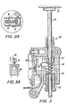
- a sheet separation and feeding apparatus is shown in Figure 2 that employs a feed head mechanism 70 shown in Figure 2 which pivots about the feed head pivot point 71.
- the feed head 70 includes everything shown except the paper stack 35 and the abutment for sensor 80.
- the dynamic stack normal force is shown as F S" . This is a force applied to the paper stack 35 by feed belt 72 due to the feed head balancing around the pivot point 71 and the effect of drive torques supplied to the feed head through the pivot point.
- Belt drives (not shown) transfer power to the feed belt 72 and take-away rolls 75 and 76.
- the normal force between the feeding component and the stack is a critical parameter. If F S" is too large, multifeeding and sheet damage will occur. If F sn is too small, misfeeding will occur. In some feeders, such as the present, the sheet is fed to a separation station. Once the sheet is in the separation station, it no longer has to be driven by the original value of stack normal force. At this point, it is advantageous to reduce the stack normal force in order to reduce the tendency to drive a second sheet through the separation station formed between feed belt 72 and retard roll 77. To accomplish this end result, a sensor 82 is shown in Figure 2 which senses the presence of a sheet in the separation station and causes the stack normal force to be reduced through means to be described hereinafter. Reducing F sn also reduces compression forces in the sheet thereby reducing sheet damage tendencies. This is especially important when feeding lightweight, curled sheets.
- the retard separator mechanism 70 is mounted on a frame 78 that is pivoted about axis 71.
- controller 38 actuates solenoid 90 which through retracting plunger 91 pivots frame 78 about axis 71 slightly and, as a result, decreases the normal force of the feed member against the stack.
- the stack normal force could be reduced to zero or lifted completely off the stack if desired, however, for optimum results, the stack normal force is reduced from 0.2 to 0.05 Kg (.5 to .1 Ib.).
- the force in the retard nip along with the reduced normal force will cause the belt to drive the first sheet through the nip and into the take-away rolls 75 and 76. Because the stack normal force has been reduced, i.e., stack force relief has been applied, it should not contribute enough drive force to the second sheet to drive it through the nip, thus reducing the probability of a multifeed.
- the controller will deactuate solenoid 90 causing the feed head to assume its original position and stack normal force value thereby increasing the stack normal force to 0.2 Kg (.5 lb.) in order to feed a sheet from the stack, i.e., the stack force is enhanced.
- sheet is used herein to mean substrates of any kind.
- This feeder employs independent drives for the feed belt 72 through drive roll 74 and take-away rolls 75 and 76 through drive roll 75.
- roll 75 as the drive roll, one clutch is used to drive the feed belt and one clutch to drive the take-away rolls.
- a wait sensor 100 is stationed at the take-away rolls, i.e., away from the retard roll nip. Only one clutch pulse per sheet is required with this two clutch approach as opposed to a one clutch approach that would require one clutch pulse to bring a sheet to the wait sensor which would be placed on the retard roll side of the take-away rolls and a second clutch pulse to drive the sheet into the take-away rolls.
- An early feed belt restart logic is used with this independent drive system.
- the logic restarts the feed belt (after wait time has elapsed) as soon as there is no paper at the stack normal force relief sensor 82 or as soon as there is no paper at the wait sensor 100, whichever occurs first.
- the wait sensor is also used as a jam detector.
- feed belt 72 and retard roll 77 are shown in the disclosed embodiment of the present invention, it should be understood that a different feed means, such as, a roll, paddle wheel, etc., could replace the belt and be used together with a dual roll retard nip if one desired.
- the paper feeders 34 and 36 have a drag brake controlled retard roll 77. This is an unusual retard feeder characteristic.
- the retard brake torque and other feed head critical parameters are selected so that with one sheet of paper through the retard nip the retard roll rotates in the feed direction and with two sheets of paper through the retard nip the roll is fixed.
- the pick off idler feed belt surface speed Vp is > the free span surface speed V, > the nip surface speed V " .
- the neutral axis (N.A.) the speed is equal to the V f value throughout the belt path.
- the surface speed increases since the surface here is stretched relative to the N.A.
- the surface is compressed as the belt is bent around the retard roll relative to the N.A. and the surface speed decreases.
- the torque applied to the retard brake with two sheets through the retard nip depends on many factors, including dynamic feed belt tension. Dynamic feed belt tension is increased by increases in dynamic stack normal force F sn . So smaller values of F sn give smaller torques applied to the retard roll. When the two sheets through applied torque exceeds the retard brake torque, a multifeed results. As the brake is used by repeated sheet feeds, its available torque is reduced. So reducing F sn extends brake life.
- SFR Small motion
- Minimum motion refers to the slight feed head pivoting motion when the SFR device is actuated. The F sn change is accomplished by rebalancing the pivoting feed head.
- Minimum motion aspect of the device is important since it reduces the time required for SFR to act. In cases where feed heads were moved from a stack of sheets in the past, the pivoting feed head motion was used to move the feed belt away from the sheets once a sheet had been fed. An example is disclosed in US-A--4074802. This required considerable cycle time. Feed head mass and extent of motion required were critical. The motionless approach of the present invention reduces cycle time requirements to a much smaller value.
- the rebalancing solenoid plunger 91 in Figure 2A is in contact with a preloaded, low rate, close wound coil spring module 92.
- the solenoid When the solenoid is actuated the plunger begins to move as soon as its magnetic field has adequately developed.
- the full feed head balancing force is available, i.e., the SFR function has been achieved, at this time.
- the plunger continues to move to its home position very little change in the balancing, i.e., no functional change in F S" , occurs due to the low spring rate of the spring module that includes spring 93.
- the present paper feeder has dual modes of operation, i.e., in one mode, it acts as a stack force relief means to relieve the stack normal force and prevent multifeeds. In another mode, the feeder acts to increase the stack normal force in order to enhance sheet feeding and reduce misfeeds.
- a motor is actuated to raise paper stack 35 which is mounted on an elevator (not shown) until plunger 81 of sensor 80 contacts abutment 89.
- the sensor is adjusted such that the stack normal force of the idler and belt against the stack 35 is 0.2 Kg (.5 Ib.) when the elevator motor is stopped.
- This stack height sensor combines smooth/ frictionless linear motion with exacting positional control.
- the sensor comprises, as shown in Figure 3A, housing 83 for a plunger 81 with drag forces on the plunger being controlled by clearances, part finish and material selection.
- the plunger 81 is in turn loaded by a compression spring 84 and is made adjustable by screw or bushing 85 which grounds the free end of the spring.
- the plunger has a flag 86 mounted on a shoulder 87 which as it moves in a line or direction, blocks and unblocks an optoelectrical sensor 88 as shown in Figure 3a. This in turn signals the logic in controller 38 as to when the elevator tray must be indexed to maintain proper feeding.
- This sensor works in conjunction with stack force relief mechanism 70 to provide an automatic two step system of normal force adjustment for the friction retard feeders shown in Figure 2.
- a paper feeder that enjoys a wide latitude in sheet feeding by the employment of stack normal force relief (SFR) that is characterized by reduction of the applied normal force to a stack to a lower level when paper is seen at a point that is about 3.2 mm (1 inch) inside the feed, retard nip entrance.
- SFR stack normal force relief
- an optical sensor detects the sheet and alters a pivoting feed head assembly balance by applying an additional moment. The additional moment is applied by a solenoid working through a low rate, preloaded spring module to the pivoting feed head assembly.
- the stack normal force is reset to the previous level.
Landscapes
- Physics & Mathematics (AREA)
- General Physics & Mathematics (AREA)
- Sheets, Magazines, And Separation Thereof (AREA)
Claims (7)
Applications Claiming Priority (4)
| Application Number | Priority Date | Filing Date | Title |
|---|---|---|---|
| US06/420,964 US4561644A (en) | 1982-09-21 | 1982-09-21 | Sheet feeding and separating apparatus with stack force relief/enhancement |
| US420964 | 1982-09-21 | ||
| US06/420,966 US4475732A (en) | 1982-09-21 | 1982-09-21 | Sheet feeding and separating apparatus with stack force relief/enhancement |
| US420966 | 1995-04-13 |
Publications (3)
| Publication Number | Publication Date |
|---|---|
| EP0104086A2 EP0104086A2 (fr) | 1984-03-28 |
| EP0104086A3 EP0104086A3 (en) | 1984-07-18 |
| EP0104086B1 true EP0104086B1 (fr) | 1987-06-16 |
Family
ID=27025052
Family Applications (1)
| Application Number | Title | Priority Date | Filing Date |
|---|---|---|---|
| EP19830305561 Expired EP0104086B1 (fr) | 1982-09-21 | 1983-09-21 | Dispositif et procédé pour l'alimentation et la séparation de feuilles |
Country Status (2)
| Country | Link |
|---|---|
| EP (1) | EP0104086B1 (fr) |
| DE (1) | DE3372141D1 (fr) |
Family Cites Families (7)
| Publication number | Priority date | Publication date | Assignee | Title |
|---|---|---|---|---|
| BE795206A (fr) * | 1972-02-11 | 1973-08-09 | Xerox Corp | Alimentation en feuilles d'appareils xerographiques |
| DE2309756A1 (de) * | 1973-02-27 | 1974-09-12 | Licentia Gmbh | Einrichtung zur abgabe von einzelnen briefen und aehnlichen flachen sendungen aus einem stapel |
| US3934869A (en) * | 1973-12-20 | 1976-01-27 | Xerox Corporation | Sheet separating and feeding apparatus |
| US4025187A (en) * | 1974-09-05 | 1977-05-24 | Xerox Corporation | Buckle control system |
| US3995952A (en) * | 1976-03-01 | 1976-12-07 | Xerox Corporation | Sheet feeding apparatus |
| US4074902A (en) * | 1976-07-23 | 1978-02-21 | Addressograph-Multigraph Corporation | Sheet feeder |
| JPS5769481A (en) * | 1980-10-17 | 1982-04-28 | Fujitsu Ltd | Document hopper device |
-
1983
- 1983-09-21 EP EP19830305561 patent/EP0104086B1/fr not_active Expired
- 1983-09-21 DE DE8383305561T patent/DE3372141D1/de not_active Expired
Also Published As
| Publication number | Publication date |
|---|---|
| EP0104086A2 (fr) | 1984-03-28 |
| DE3372141D1 (en) | 1987-07-23 |
| EP0104086A3 (en) | 1984-07-18 |
Similar Documents
| Publication | Publication Date | Title |
|---|---|---|
| US4475732A (en) | Sheet feeding and separating apparatus with stack force relief/enhancement | |
| US5253862A (en) | Adjustable normal force edge registering apparatus | |
| US4397459A (en) | Apparatus for detecting the flotation level in an air supported sheet separating and feeding device | |
| JPH048112Y2 (fr) | ||
| US4561644A (en) | Sheet feeding and separating apparatus with stack force relief/enhancement | |
| US4744555A (en) | Sheet transport and registration apparatus | |
| US4947214A (en) | Transfer apparatus | |
| CA1253892A (fr) | Dispositif a succion avec surface rayee pour le prelevement de feuilles en somment d'une pile et leur transfert | |
| US4381860A (en) | Paddle wheel retard feeder | |
| US5921540A (en) | Vacuum corrugation feeder with a retractable corrugator | |
| US5346199A (en) | Adjustable nudger roll normal force using multiple springs | |
| US4533135A (en) | Jammed sheet removal aid in a reproducing machine | |
| US3866901A (en) | Reverse buckle feeder | |
| US4487407A (en) | Trail edge copy registration system | |
| US5146286A (en) | Compact copy sheet input/output apparatus for an electrophotographic printing machine | |
| US5333848A (en) | Retard feeder | |
| EP0104085B1 (fr) | Dispositif d'alimentation et de séparation de feuilles | |
| US5316288A (en) | Sheet handling apparatus and method for registering a sheet using a gate device | |
| USRE33843E (en) | Sheet transport and registration apparatus | |
| EP0104086B1 (fr) | Dispositif et procédé pour l'alimentation et la séparation de feuilles | |
| US4327904A (en) | Electrostatically assisted retard feeder method and apparatus | |
| EP0353270A1 (fr) | Dispositif ameliore de separation de feuilles. | |
| US5348282A (en) | Self adjusting feed roll | |
| JP2522058B2 (ja) | シ―ト材給送装置 | |
| JP2522391B2 (ja) | シ―ト材給送装置 |
Legal Events
| Date | Code | Title | Description |
|---|---|---|---|
| PUAI | Public reference made under article 153(3) epc to a published international application that has entered the european phase |
Free format text: ORIGINAL CODE: 0009012 |
|
| AK | Designated contracting states |
Designated state(s): DE GB IT |
|
| PUAL | Search report despatched |
Free format text: ORIGINAL CODE: 0009013 |
|
| AK | Designated contracting states |
Designated state(s): DE GB IT |
|
| 17P | Request for examination filed |
Effective date: 19841208 |
|
| 17Q | First examination report despatched |
Effective date: 19860129 |
|
| GRAA | (expected) grant |
Free format text: ORIGINAL CODE: 0009210 |
|
| AK | Designated contracting states |
Kind code of ref document: B1 Designated state(s): DE GB IT |
|
| REF | Corresponds to: |
Ref document number: 3372141 Country of ref document: DE Date of ref document: 19870723 |
|
| ITF | It: translation for a ep patent filed | ||
| PLBE | No opposition filed within time limit |
Free format text: ORIGINAL CODE: 0009261 |
|
| STAA | Information on the status of an ep patent application or granted ep patent |
Free format text: STATUS: NO OPPOSITION FILED WITHIN TIME LIMIT |
|
| 26N | No opposition filed | ||
| ITTA | It: last paid annual fee | ||
| PGFP | Annual fee paid to national office [announced via postgrant information from national office to epo] |
Ref country code: GB Payment date: 19990915 Year of fee payment: 17 |
|
| PGFP | Annual fee paid to national office [announced via postgrant information from national office to epo] |
Ref country code: DE Payment date: 19990927 Year of fee payment: 17 |
|
| PG25 | Lapsed in a contracting state [announced via postgrant information from national office to epo] |
Ref country code: GB Free format text: LAPSE BECAUSE OF NON-PAYMENT OF DUE FEES Effective date: 20000921 |
|
| GBPC | Gb: european patent ceased through non-payment of renewal fee |
Effective date: 20000921 |
|
| PG25 | Lapsed in a contracting state [announced via postgrant information from national office to epo] |
Ref country code: DE Free format text: LAPSE BECAUSE OF NON-PAYMENT OF DUE FEES Effective date: 20010601 |