EP0103637B1 - Subarachnoid bolts - Google Patents
Subarachnoid bolts Download PDFInfo
- Publication number
- EP0103637B1 EP0103637B1 EP83901462A EP83901462A EP0103637B1 EP 0103637 B1 EP0103637 B1 EP 0103637B1 EP 83901462 A EP83901462 A EP 83901462A EP 83901462 A EP83901462 A EP 83901462A EP 0103637 B1 EP0103637 B1 EP 0103637B1
- Authority
- EP
- European Patent Office
- Prior art keywords
- bolt
- tubular member
- subarachnoid
- skull
- bolt half
- Prior art date
- Legal status (The legal status is an assumption and is not a legal conclusion. Google has not performed a legal analysis and makes no representation as to the accuracy of the status listed.)
- Expired
Links
Images

Classifications
-
- A—HUMAN NECESSITIES
- A61—MEDICAL OR VETERINARY SCIENCE; HYGIENE
- A61B—DIAGNOSIS; SURGERY; IDENTIFICATION
- A61B5/00—Measuring for diagnostic purposes; Identification of persons
- A61B5/03—Measuring fluid pressure within the body other than blood pressure, e.g. cerebral pressure ; Measuring pressure in body tissues or organs
- A61B5/031—Intracranial pressure
Definitions
- the present invention concerns a subarachnoid bolt for use in measuring intracranial pressure.
- Several devices have been utilized to perform such measurements. These include intraventricular catheters, subarachnoid bolts and solid state or implantable transducers. This invention relates to improvements in subarachnoid bolts.
- Subarachnoid bolts for measuring or monitoring intracranial pressure have been known for some time.
- One of the more widely utilized bolts commonly referred to as a "Philly” bolt, is comprised essentially of stainless steel or similar material and includes an external screw thread at its lower end which is intended to be screwed into a twist drill hole formed in a patient's skull. The extreme end of the bolt enters the subarachnoid space over the cerebral hemisphere.
- EP-A-0074 037 discloses a subarachnoid bolt for use in measuring intracranial pressure including a lower bolt half having an enlarged flange and a coaxially arranged tubular member extending downwardly from said flange, at least a part of said tubular member being radially expandable so that the same can be secured to the patient's skull and an upper bolt half adapted to be screwed to the top of said lower bolt half.
- the present invention overcomes the defects of the prior art known to Applicant and provides a subarachnoid bolt which can be easily secured to substantially any skull.
- the bolt of the present invention includes a lower bolt half having an enlarged flange and a coaxially arranged tubular member extending downwardly from said flange, said tubular member being adapted to be inserted into a substantially complementary shaped hole in a patient's skull with said flange overlying the outer surface of the skull around said hole, at least a part of said tubular member being radially expandable so that the same can be secured to the patient's skull;
- the bolt is securely held in place when the free end of a tubular element carried by the upper bolt half enters the tubular member and cams the lowermost end thereof radially outwardly when the two bolt halves are screwed together.
- a sleeve on the lower bolt half bulges outwardly against the walls of the hole when the two bolt halves are screwed together.
- Figure 1 a first embodiment of a subarachnoid bolt constructed in accordance with the principles of the present invention and designated generally as 10.
- bolt 10 is shown secured to the skull 12 of a patient.
- Bolt 10 is comprised of two parts: a lower bolt half 14 and an upper bolt half 16. As shown most clearly in Figures 2 and 3, lower bolt half 14 is essentially circular in cross section except for the upper portion thereof which is squared as shown at 18 to form a means by which a wrench or similar tool can hold the lower bolt half 14 to prevent the same from rotating. The reason for this will become more readily apparent hereinafter.
- the lower section of lower bolt half 14 is reduced in diameter and forms a tubular member 20 which is coaxially aligned with the remaining parts of the bolt.
- An enlarged flange 22 is thereby formed above the tubular member 20.
- a sealing washer 24 rests against the flange 22 and around the upper part of the tubular member 20.
- the tubular member 20 is adapted to be inserted into a substantially complementary shaped hole 26 in a patient's skull 12.
- the length of the tubular member 20 is selected so that the lowermost end 28 thereof which is slightly bulbous lies just below the lowermost surface of the skull 12.
- the flange 22 and washer 24 overlie the outer surface of the skull 12 around the hole 26.
- Lower bolt half 14 is substantially hollow, having a channel passing entirely therethrough.
- An internal screw head 30 is formed in the uppermost part and the inner surface of the lowermost end 28 is substantially conically shaped as shown at 32.
- the wall of the lowermost end 28 of the tubular member 20 also includes a plurality of axially extending slits 34 therein. In the preferred embodiment of the invention, four such slits are shown (see Figure 2). This is by way of example only as the invention could function with fewer or more such slits.
- the purpose of the slits 34 is to weaken the wall of the lowermost end portion 28 slightly so that the same can be flexed outwardly when the bolt is in use as will be explained more clearly hereinafter. With the end portion 28 flexed outwardly, the bulbous portion forces against the undersurface of the skull 12 to retain the bolt in place.
- the upper bolt half 16 has a main body portion with a concentrically arranged tubular element 36 extending downwardly therefrom.
- a squared section 38 similar to section 18 also allows the upper bolt half to be held by a wrench or similar tool so that the same can be turned relative to the lower bolt half.
- a washer 40 similar to washer 24 extends around the uppermost part of the tubular element 36.
- the uppermost part of the upper bolt half 16 carries a coaxially arranged adapter or connector 42 which is utilized for connecting the bolt to remotely located sensing and/or measuring equipment.
- An external screw thread 44 is formed on the upper end of the tubular element 36.
- This screw thread 44 is complementary to the screw thread 30 on the lower bolt half 14 so that the two bolt halves can be secured together with the tubular element 36 entering the interior of the lower bolt half 14.
- the forwardmost end 46 of the tubular element 36 is also substantially conically shaped and as the two bolt halves are screwed together, this end 46 moves downwardly and pushes against the conical inner surface 32 to cam the lower end 28 of the lower bolt half 14 outwardly to secure the bolt in place.
- a conventional pin 48 with handle 50 may also be utilized to seal the interior of the bolt 10 whenever the same is not being utilized for measuring intracranial pressure.
- Bolt 10 is used in the following manner.
- a hole 26 is first drilled in the patient's skull 12 at the appropriate position.
- Bolt halves 14 and 16 are separated and tubular member 20 of bolt half 14 is passed through the hole 26 with the bulbous end 28 lying just below the surface of the skull 12 and the washer 24 and flange 22 lying above the skull for sealing the same.
- the tubular element 36 of the upper bolt half 16 is then inserted into the interior of the lower bolt half 14.
- a wrench is then used to hold the lower bolt half 14 while a second wrench or similar tool is used to turn the upper bolt half 16 so that the two bolt halves are threaded together.
- the lowermost end 46 of the tubular element 36 will function as a cam to flex the lowermost end 28 of the tublar member 20 outwardly to secure the bolt in position on the skull as shown in Figure 4.
- FIG. 5-8 A second embodiment of the invention is illustrated in Figures 5-8.
- a subarachnoid bolt constructed in accordance with the principles of this embodiment of the invention is designated generally in Figure 5 as 110.
- bolt 110 is comprised essentially of two parts: a lower bolt half 114 and an upper bolt half 116.
- lower bolt half 114 is essentially circular in cross section except for the upper portion thereof which is squared as shown at 118 to form a means by which a wrench or similar tool 119 can hold the lower bolt half 114 to prevent the same from rotating.
- the lower section of lower bolt half 114 is reduced in diameter and forms a tubular member 120 which is coaxially aligned with the remaining parts of the bolt.
- An enlarged flange 122 is thereby formed above the tubular member 120.
- a sealing washer 124 rests against the flange 122 and around the upper part of the tublar member 120.
- Screw 126 Extending upwardly through the tubular member 120 is a hollow screw 126.
- the lowermost portion of the hollow screw 126 has an enlarged head 128 which abuts the extreme lower edge 130 of the tubular member 120 which prevents upward movement of the hollow screw 126.
- Screw 126 is long enough to extend slightly above the upper surface of the lower bolt half 114 and has this upper portion threaded as shown at 132 in Figure 7.
- Adjacent the upper portion of the screw 126 one side thereof is flattened as shown at 134.
- This flattened portion 134 is engaged by a set screw 136 which passes through the side wall of the upper part of the lower bolt half 114.
- the set screw 136 does not tightly engage the flattened surface 134 of the screw 126. Rather, it is intended to prevent rotational movement of the screw 126while allowing limited axial movement. The reasons for this will become more readily apparent hereinafter.
- the tubular member 120 is adapted to be inserted into a substantially complementary shaped hole 26 in a patient's skull 12.
- the length of the tubular member 120 is selected so that the lowermost end including the lower portion 128 of the screw 126 is just below the lowermost surface of the skull 12. In this position, the flange 122 and washer 124 overlie the outer surface of the skull 12 around the hole 26 in substantially the same manner as the bolt 10 described in Figures 1-4.
- the upper bolt half 116 is also substantially circular in cross section except for the squared section 138 which is similar in shape to the squared section 118 on the lower bolt half.
- the uppermost part of the upper bolt half 116 carries a coaxially arranged adapter or connector 142 which is utilized for connecting the bolt to remotely located sensing and/or measuring equipment.
- the lower end of the upper bolt half 116 has an internal thread 144 formed therein which is adapted to cooperate with the threaded portion 132 at the upper end of the screw 126.
- Bolt 110 is used in the following manner. As with bolt 10, a hole 26 is first drilled in the patient's skull 12 at the appropriate position. Bolt halves 114 and 116 are separated and tubular member 120 of bolt half 114 is passed through the hole 26 with the lower end 128 of the screw 126 and the lower end 130 of the tubular member 120 lying just below the surface of the skull 12 and the washer 124 and flange 122 lying above the skull for sealing the same. The upper bolt half 116 is then screwed onto the lower bolt half by engaging the internal threads 144 with the external threads 132. Wrench 119 is utilized to hold the lower bolt half 114 in a stationary position while a second wrench or similar tool is used to turn the upper bolt half 116.
- the adapters 42 and 142 and the screws 126 and 136 are comprised of stainless steel or the like while the remaining parts of the bolt are preferably made of relatively rigid plastic.
- the washers are, of course, preferably comprised of a somewhat softer material so that they will produce the desired sealing function.
- the tubular member 120 must be relatively rigid but flexible enough to flex outwardly to perform its sealing function.
Landscapes
- Health & Medical Sciences (AREA)
- Life Sciences & Earth Sciences (AREA)
- Biomedical Technology (AREA)
- Molecular Biology (AREA)
- Hematology (AREA)
- Biophysics (AREA)
- Pathology (AREA)
- Engineering & Computer Science (AREA)
- Neurosurgery (AREA)
- Heart & Thoracic Surgery (AREA)
- Medical Informatics (AREA)
- Physics & Mathematics (AREA)
- Surgery (AREA)
- Animal Behavior & Ethology (AREA)
- General Health & Medical Sciences (AREA)
- Public Health (AREA)
- Veterinary Medicine (AREA)
- Measuring And Recording Apparatus For Diagnosis (AREA)
- Surgical Instruments (AREA)
Description
- The present invention concerns a subarachnoid bolt for use in measuring intracranial pressure. Several devices have been utilized to perform such measurements. These include intraventricular catheters, subarachnoid bolts and solid state or implantable transducers. This invention relates to improvements in subarachnoid bolts.
- Subarachnoid bolts for measuring or monitoring intracranial pressure have been known for some time. One of the more widely utilized bolts, commonly referred to as a "Philly" bolt, is comprised essentially of stainless steel or similar material and includes an external screw thread at its lower end which is intended to be screwed into a twist drill hole formed in a patient's skull. The extreme end of the bolt enters the subarachnoid space over the cerebral hemisphere.
- EP-A-0074 037 discloses a subarachnoid bolt for use in measuring intracranial pressure including a lower bolt half having an enlarged flange and a coaxially arranged tubular member extending downwardly from said flange, at least a part of said tubular member being radially expandable so that the same can be secured to the patient's skull and an upper bolt half adapted to be screwed to the top of said lower bolt half. (That document forms a part of the prior art under Article 54(3) and (4) EPC only, with respect to all the designated Contracting States, except Luxembourg.)
- While known subarachnoid bolts have met with some success, they have also suffered from many problems particularly with patients with very thin skulls such as neonatal patients. With such patients and in many other cases, it is extremely difficult and sometimes impossible to secure the bolt to the skull by screwing the same thereto.
- The present invention overcomes the defects of the prior art known to Applicant and provides a subarachnoid bolt which can be easily secured to substantially any skull.
- The bolt of the present invention includes a lower bolt half having an enlarged flange and a coaxially arranged tubular member extending downwardly from said flange, said tubular member being adapted to be inserted into a substantially complementary shaped hole in a patient's skull with said flange overlying the outer surface of the skull around said hole, at least a part of said tubular member being radially expandable so that the same can be secured to the patient's skull;
- means on said lower bolt half allowing the same to be held to prevent rotation thereof;
- an upper bolt half adapted to be screwed to the top of said lower bolt half, and means for causing said at least part of said tubular member to radially expand when said two bolt halves are screwed together.
- In one embodiment, the bolt is securely held in place when the free end of a tubular element carried by the upper bolt half enters the tubular member and cams the lowermost end thereof radially outwardly when the two bolt halves are screwed together. In a second embodiment, a sleeve on the lower bolt half bulges outwardly against the walls of the hole when the two bolt halves are screwed together.
- For the purpose of illustrating the invention, there are shown in the accompanying drawings forms which are presently preferred; it being understood that the invention is not intended to be limited to the precise arrangements and instrumentalities shown.
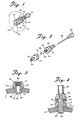
- Figure 1 is a perspective view of a subarachnoid bolt constructed in accordance with the principles of the present invention;
- Figure 2 is an exploded perspective view of the bolt shown in Figure 1;
- Figure 3 is a cross-sectional view of the lower bolt half inserted in a hole in a patient's skull;
- Figure 4 is a cross-sectional view of the bolt secured to a patient's skull;
- Figure 5 is a perspective view of a second embodiment of a subarachnoid bolt according to the invention;
- Figure 6 is an exploded perspective view of the bolt shown in Figure 5;
- Figure 7 is a cross-sectional view of the lower half of the bolt of Figure 5 inserted in a hole in a patient's skull; and
- Figure 8 is a cross-sectional view of the bolt of Figure 5 secured to a patient's skull.
- Referring now to the drawings in detail wherein like reference numerals have been used throughout the various figures to designate like elements, there is shown in Figure 1 a first embodiment of a subarachnoid bolt constructed in accordance with the principles of the present invention and designated generally as 10. In Figure 1,
bolt 10 is shown secured to theskull 12 of a patient. -
Bolt 10 is comprised of two parts: alower bolt half 14 and anupper bolt half 16. As shown most clearly in Figures 2 and 3,lower bolt half 14 is essentially circular in cross section except for the upper portion thereof which is squared as shown at 18 to form a means by which a wrench or similar tool can hold thelower bolt half 14 to prevent the same from rotating. The reason for this will become more readily apparent hereinafter. - The lower section of
lower bolt half 14 is reduced in diameter and forms atubular member 20 which is coaxially aligned with the remaining parts of the bolt. An enlargedflange 22 is thereby formed above thetubular member 20. A sealingwasher 24 rests against theflange 22 and around the upper part of thetubular member 20. - As shown most clearly in Figure 3, the
tubular member 20 is adapted to be inserted into a substantially complementaryshaped hole 26 in a patient'sskull 12. The length of thetubular member 20 is selected so that thelowermost end 28 thereof which is slightly bulbous lies just below the lowermost surface of theskull 12. Theflange 22 andwasher 24 overlie the outer surface of theskull 12 around thehole 26. -
Lower bolt half 14 is substantially hollow, having a channel passing entirely therethrough. Aninternal screw head 30 is formed in the uppermost part and the inner surface of thelowermost end 28 is substantially conically shaped as shown at 32. The wall of thelowermost end 28 of thetubular member 20 also includes a plurality of axially extendingslits 34 therein. In the preferred embodiment of the invention, four such slits are shown (see Figure 2). This is by way of example only as the invention could function with fewer or more such slits. The purpose of theslits 34 is to weaken the wall of thelowermost end portion 28 slightly so that the same can be flexed outwardly when the bolt is in use as will be explained more clearly hereinafter. With theend portion 28 flexed outwardly, the bulbous portion forces against the undersurface of theskull 12 to retain the bolt in place. - The details of the
upper bolt half 16 are shown most clearly in Figures 2 and 4. As with thelower bolt half 14, theupper bolt half 16 has a main body portion with a concentrically arrangedtubular element 36 extending downwardly therefrom. Asquared section 38 similar tosection 18 also allows the upper bolt half to be held by a wrench or similar tool so that the same can be turned relative to the lower bolt half. Awasher 40 similar towasher 24 extends around the uppermost part of thetubular element 36. The uppermost part of theupper bolt half 16 carries a coaxially arranged adapter orconnector 42 which is utilized for connecting the bolt to remotely located sensing and/or measuring equipment. - An
external screw thread 44 is formed on the upper end of thetubular element 36. Thisscrew thread 44 is complementary to thescrew thread 30 on thelower bolt half 14 so that the two bolt halves can be secured together with thetubular element 36 entering the interior of thelower bolt half 14. Theforwardmost end 46 of thetubular element 36 is also substantially conically shaped and as the two bolt halves are screwed together, thisend 46 moves downwardly and pushes against the conicalinner surface 32 to cam thelower end 28 of thelower bolt half 14 outwardly to secure the bolt in place. Aconventional pin 48 withhandle 50 may also be utilized to seal the interior of thebolt 10 whenever the same is not being utilized for measuring intracranial pressure. -
Bolt 10 is used in the following manner. Ahole 26 is first drilled in the patient'sskull 12 at the appropriate position.Bolt halves tubular member 20 ofbolt half 14 is passed through thehole 26 with thebulbous end 28 lying just below the surface of theskull 12 and thewasher 24 andflange 22 lying above the skull for sealing the same. Thetubular element 36 of theupper bolt half 16 is then inserted into the interior of thelower bolt half 14. A wrench is then used to hold thelower bolt half 14 while a second wrench or similar tool is used to turn theupper bolt half 16 so that the two bolt halves are threaded together. Eventually, thelowermost end 46 of thetubular element 36 will function as a cam to flex thelowermost end 28 of thetublar member 20 outwardly to secure the bolt in position on the skull as shown in Figure 4. - A second embodiment of the invention is illustrated in Figures 5-8. A subarachnoid bolt constructed in accordance with the principles of this embodiment of the invention is designated generally in Figure 5 as 110.
- As with
bolt 10,bolt 110 is comprised essentially of two parts: alower bolt half 114 and anupper bolt half 116. As shown most clearly in Figures 6-8,lower bolt half 114 is essentially circular in cross section except for the upper portion thereof which is squared as shown at 118 to form a means by which a wrench orsimilar tool 119 can hold thelower bolt half 114 to prevent the same from rotating. - The lower section of
lower bolt half 114 is reduced in diameter and forms atubular member 120 which is coaxially aligned with the remaining parts of the bolt. An enlargedflange 122 is thereby formed above thetubular member 120. A sealingwasher 124 rests against theflange 122 and around the upper part of the tublarmember 120. - Extending upwardly through the
tubular member 120 is ahollow screw 126. The lowermost portion of thehollow screw 126 has anenlarged head 128 which abuts the extremelower edge 130 of thetubular member 120 which prevents upward movement of thehollow screw 126.Screw 126 is long enough to extend slightly above the upper surface of thelower bolt half 114 and has this upper portion threaded as shown at 132 in Figure 7. Adjacent the upper portion of thescrew 126, one side thereof is flattened as shown at 134. This flattenedportion 134 is engaged by aset screw 136 which passes through the side wall of the upper part of thelower bolt half 114. Theset screw 136 does not tightly engage the flattenedsurface 134 of thescrew 126. Rather, it is intended to prevent rotational movement of the screw 126while allowing limited axial movement. The reasons for this will become more readily apparent hereinafter. - As shown most clearly in Figures 7 and 8, the
tubular member 120 is adapted to be inserted into a substantially complementary shapedhole 26 in a patient'sskull 12. The length of thetubular member 120 is selected so that the lowermost end including thelower portion 128 of thescrew 126 is just below the lowermost surface of theskull 12. In this position, theflange 122 andwasher 124 overlie the outer surface of theskull 12 around thehole 26 in substantially the same manner as thebolt 10 described in Figures 1-4. - The
upper bolt half 116 is also substantially circular in cross section except for thesquared section 138 which is similar in shape to the squaredsection 118 on the lower bolt half. The uppermost part of theupper bolt half 116 carries a coaxially arranged adapter orconnector 142 which is utilized for connecting the bolt to remotely located sensing and/or measuring equipment. The lower end of theupper bolt half 116 has aninternal thread 144 formed therein which is adapted to cooperate with the threadedportion 132 at the upper end of thescrew 126. -
Bolt 110 is used in the following manner. As withbolt 10, ahole 26 is first drilled in the patient'sskull 12 at the appropriate position. Bolt halves 114 and 116 are separated andtubular member 120 ofbolt half 114 is passed through thehole 26 with thelower end 128 of thescrew 126 and thelower end 130 of thetubular member 120 lying just below the surface of theskull 12 and thewasher 124 andflange 122 lying above the skull for sealing the same. Theupper bolt half 116 is then screwed onto the lower bolt half by engaging theinternal threads 144 with theexternal threads 132.Wrench 119 is utilized to hold thelower bolt half 114 in a stationary position while a second wrench or similar tool is used to turn theupper bolt half 116. Since thescrew 126 is prevented from rotational movement byset screw 136, it is eventually drawn upwardly as theupper bolt half 116 is turned.Head 128 at the end ofscrew 126 engages thelower end 130 of thetubular member 120 and attempts to push this upwardly. Since the entiretubular member 120 cannot move upwardly, it eventually expands or bulges outwardly and seals tightly against the inner wall of thehole 26 in theskull 12, thus securing the bolt in position. This is clearly shown in Figure 8. - Any suitable materials may be utilized in the manufacture of the
bolts adapters screws tubular member 120 must be relatively rigid but flexible enough to flex outwardly to perform its sealing function. - The present invention may be embodied in other specific forms without departing from the scope of the invention, which is defined in the appended claims.
Claims (9)
Priority Applications (1)
| Application Number | Priority Date | Filing Date | Title |
|---|---|---|---|
| AT83901462T ATE28555T1 (en) | 1982-03-15 | 1983-03-15 | SUBARACHNOIDAL PROBE. |
Applications Claiming Priority (2)
| Application Number | Priority Date | Filing Date | Title |
|---|---|---|---|
| US06/358,444 US4438773A (en) | 1982-03-15 | 1982-03-15 | Subarachnoid bolt |
| US358444 | 1982-03-15 |
Publications (3)
| Publication Number | Publication Date |
|---|---|
| EP0103637A1 EP0103637A1 (en) | 1984-03-28 |
| EP0103637A4 EP0103637A4 (en) | 1985-04-11 |
| EP0103637B1 true EP0103637B1 (en) | 1987-07-29 |
Family
ID=23409682
Family Applications (1)
| Application Number | Title | Priority Date | Filing Date |
|---|---|---|---|
| EP83901462A Expired EP0103637B1 (en) | 1982-03-15 | 1983-03-15 | Subarachnoid bolts |
Country Status (7)
| Country | Link |
|---|---|
| US (1) | US4438773A (en) |
| EP (1) | EP0103637B1 (en) |
| JP (1) | JPS59500357A (en) |
| AU (1) | AU1551683A (en) |
| CA (1) | CA1193474A (en) |
| DE (1) | DE3372697D1 (en) |
| WO (1) | WO1983003190A1 (en) |
Families Citing this family (32)
| Publication number | Priority date | Publication date | Assignee | Title |
|---|---|---|---|---|
| FR2557792B1 (en) * | 1983-11-22 | 1988-07-22 | Lacombe Jacques | INTRACRANEAN PRESSURE SENSOR. |
| US4600013A (en) * | 1984-05-08 | 1986-07-15 | Howard Landy | Intracranial pressure monitoring probe |
| JPH0712339B2 (en) * | 1985-03-22 | 1995-02-15 | コドマン・アンド・シヤートレフ・インコーポレイテツド | Skull screw |
| US4677985A (en) * | 1985-08-12 | 1987-07-07 | Bro William J | Apparatus and method for determining intracranial pressure and local cerebral blood flow |
| EP0323535A1 (en) * | 1988-01-05 | 1989-07-12 | Hellige GmbH | Adapter for exchangeable implantation of biosensors in the skull bone |
| US5054497A (en) * | 1990-02-21 | 1991-10-08 | Biomedical Monitors And Implants, Inc. | Cranial sensor attaching device and method for its use |
| US5990382A (en) * | 1990-08-29 | 1999-11-23 | Biomedical Enterprises, Inc. | Method and implant for surgical manipulation of bone |
| US5766249A (en) * | 1990-11-20 | 1998-06-16 | Griffith; Donald P. | Tissue bondable cystostomy tube and method of cystostomy tube implantation |
| WO1996037144A1 (en) * | 1995-05-26 | 1996-11-28 | White Spot Ag | Cerebral pressure measuring probe screw |
| WO1997042870A1 (en) * | 1996-05-14 | 1997-11-20 | Camino Neurocare, Inc. | Expandable parenchymal bolt |
| ATE198162T1 (en) | 1996-09-18 | 2001-01-15 | Svend Erik Borgesen | DEVICE FOR TREATING HYDROCEPHALUS |
| WO1998051214A1 (en) * | 1997-05-13 | 1998-11-19 | Camino Neurocare, Inc. | Expandable parenchymal bolt with lever activation |
| US6080134A (en) * | 1997-05-13 | 2000-06-27 | Camino Neurocare, Inc. | Expandable parenchymal bolt with lever activation |
| US6537232B1 (en) | 1997-05-15 | 2003-03-25 | Regents Of The University Of Minnesota | Intracranial pressure monitoring device and method for use in MR-guided drug delivery |
| DE19820808C2 (en) * | 1998-05-09 | 2000-11-02 | Wolfgang Fleckenstein | Insertion device for brain probes |
| US7694821B1 (en) | 1999-06-04 | 2010-04-13 | Medtronic Ps Medical, Inc. | Subdural evacuating port system |
| US7553290B1 (en) | 1999-06-04 | 2009-06-30 | Medtronic Ps Medical, Inc. | Subdural evacuating port aspiration system |
| US6923799B1 (en) | 1999-06-04 | 2005-08-02 | Wilson T. Asfora | Subdural evacuating port system |
| DK1324800T3 (en) | 2000-09-11 | 2008-11-10 | Csf Dynamics As | Liquid hunt system for treatment of hydrocephalus |
| DE10065799C1 (en) * | 2000-12-30 | 2002-04-25 | Rehau Ag & Co | Skull drainage screw has threaded hollow shaft provided with multi-sided inner profile for reception of multi-sided insertion tool |
| US20040034375A1 (en) * | 2002-05-31 | 2004-02-19 | Ruiz Larry R. | Fastening system incorporating washer for skull closure |
| US8372061B2 (en) * | 2003-05-15 | 2013-02-12 | Noberto Berna | Treatment tip incision template |
| ITPD20030102A1 (en) * | 2003-05-15 | 2004-11-16 | Norberto Berna | FORM OF SHAPE AND DEPTH FOR ENGRAVINGS WITH LASER POINTS |
| US7780679B2 (en) * | 2003-05-30 | 2010-08-24 | Innerspace Medical, Inc. | System and method for intracranial access and monitoring |
| US20080275395A1 (en) * | 2006-12-22 | 2008-11-06 | Innerspace Medical, Inc. | MRI-Compatible Temperature-Sensing Catheter |
| WO2008144232A2 (en) | 2007-05-18 | 2008-11-27 | The Johns Hopkins University | A treatment simulator for brain diseases and method of use thereof |
| WO2010093712A2 (en) * | 2009-02-10 | 2010-08-19 | Innerspace Medical, Inc. | Bolt stop system for use in accessing intracranial space |
| WO2017220108A1 (en) | 2016-06-20 | 2017-12-28 | Csf-Dynamics A/S | A shunt device and a method for shunting cerebrospinal fluid |
| EP3595515A4 (en) | 2017-03-14 | 2020-12-30 | University of Connecticut | BIODEGRADABLE PRESSURE SENSOR |
| US11826495B2 (en) | 2019-03-01 | 2023-11-28 | University Of Connecticut | Biodegradable piezoelectric ultrasonic transducer system |
| US11745001B2 (en) | 2020-03-10 | 2023-09-05 | University Of Connecticut | Therapeutic bandage |
| US12491290B2 (en) | 2020-06-08 | 2025-12-09 | University Of Connecticut | Biodegradable piezoelectric composite materials |
Family Cites Families (5)
| Publication number | Priority date | Publication date | Assignee | Title |
|---|---|---|---|---|
| US4062354A (en) * | 1975-07-01 | 1977-12-13 | Taylor H Lyndon | Intracranial pressure transducer system |
| NL181709C (en) * | 1977-02-18 | 1987-10-16 | Honeywell Bv | DEVICE FOR ADJUSTING A SKULL FOR INSTALLING A PRESSURE RECORDER. |
| NL7801416A (en) * | 1977-03-04 | 1978-09-06 | Siemens Ag | IN THE SKULL OF A PATIENT SCREWABLE ADAPTER TO RECEIVE A PRESSURE CONVERTER. |
| FR2384482A1 (en) * | 1977-03-25 | 1978-10-20 | Anvar | Sensor for monitoring intracranial pressure - has gas capsule with membrane contacting skull outer membrane to control pressure transducer |
| DE3135511C2 (en) * | 1981-09-08 | 1986-03-20 | Fraunhofer-Gesellschaft zur Förderung der angewandten Forschung e.V., 8000 München | Pressure sensor, consisting of a cylindrical cup circle with an end face designed as a membrane |
-
1982
- 1982-03-15 US US06/358,444 patent/US4438773A/en not_active Expired - Fee Related
-
1983
- 1983-03-14 CA CA000423476A patent/CA1193474A/en not_active Expired
- 1983-03-15 JP JP58501631A patent/JPS59500357A/en active Pending
- 1983-03-15 EP EP83901462A patent/EP0103637B1/en not_active Expired
- 1983-03-15 DE DE8383901462T patent/DE3372697D1/en not_active Expired
- 1983-03-15 WO PCT/US1983/000347 patent/WO1983003190A1/en not_active Ceased
- 1983-03-15 AU AU15516/83A patent/AU1551683A/en not_active Abandoned
Also Published As
| Publication number | Publication date |
|---|---|
| WO1983003190A1 (en) | 1983-09-29 |
| DE3372697D1 (en) | 1987-09-03 |
| JPS59500357A (en) | 1984-03-08 |
| EP0103637A1 (en) | 1984-03-28 |
| US4438773A (en) | 1984-03-27 |
| CA1193474A (en) | 1985-09-17 |
| EP0103637A4 (en) | 1985-04-11 |
| AU1551683A (en) | 1983-10-24 |
Similar Documents
| Publication | Publication Date | Title |
|---|---|---|
| US4438773A (en) | Subarachnoid bolt | |
| US4572212A (en) | Subarachnoid bolts | |
| EP0195455B1 (en) | Cranial screw | |
| US7604658B2 (en) | Multiple lumen sensor attachment | |
| US5054497A (en) | Cranial sensor attaching device and method for its use | |
| US4809694A (en) | Biopsy guide | |
| US5125840A (en) | Enossal single tooth implant with twisting restraint | |
| US5224939A (en) | Self locking guide catheter | |
| US7056303B2 (en) | Surgical instrument seal assembly | |
| US5989241A (en) | Drainage catheter apparatus | |
| US5464446A (en) | Brain lead anchoring system | |
| US5685715A (en) | Self-indexing transfer impression coping | |
| US6190372B1 (en) | Catheter connector | |
| EP1293228A2 (en) | Retaining device for axially restraining movement between tubular elements of a medical device | |
| EP0368473A2 (en) | Catheter with a retention structure | |
| JPH0480704B2 (en) | ||
| US4630490A (en) | Compression strain gauge transducer assembly | |
| JP5002163B2 (en) | External fixing device that increases the distance between the clamping elements | |
| JP4072974B2 (en) | Device for connecting the vertical carrier and the bone anchoring means | |
| JP2005509484A5 (en) | ||
| CA2392440C (en) | Medical device | |
| US4620458A (en) | Apparatus for screwing in set screws, which can be operated by a wrench | |
| JP2004504119A (en) | Ventricular drainage tube | |
| AU2024203882B2 (en) | Medical device for accessing the central nervous system | |
| CN213145038U (en) | Lifting component suitable for intelligent bed lifting structure |
Legal Events
| Date | Code | Title | Description |
|---|---|---|---|
| PUAI | Public reference made under article 153(3) epc to a published international application that has entered the european phase |
Free format text: ORIGINAL CODE: 0009012 |
|
| AK | Designated contracting states |
Designated state(s): AT BE CH DE FR GB LI LU NL SE |
|
| 17P | Request for examination filed |
Effective date: 19840314 |
|
| 17Q | First examination report despatched |
Effective date: 19860521 |
|
| GRAA | (expected) grant |
Free format text: ORIGINAL CODE: 0009210 |
|
| AK | Designated contracting states |
Kind code of ref document: B1 Designated state(s): AT BE CH DE FR GB LI LU NL SE |
|
| PG25 | Lapsed in a contracting state [announced via postgrant information from national office to epo] |
Ref country code: NL Effective date: 19870729 Ref country code: BE Effective date: 19870729 Ref country code: AT Effective date: 19870729 |
|
| REF | Corresponds to: |
Ref document number: 28555 Country of ref document: AT Date of ref document: 19870815 Kind code of ref document: T |
|
| PG25 | Lapsed in a contracting state [announced via postgrant information from national office to epo] |
Ref country code: SE Effective date: 19870731 |
|
| ET | Fr: translation filed | ||
| REF | Corresponds to: |
Ref document number: 3372697 Country of ref document: DE Date of ref document: 19870903 |
|
| NLV1 | Nl: lapsed or annulled due to failure to fulfill the requirements of art. 29p and 29m of the patents act | ||
| PG25 | Lapsed in a contracting state [announced via postgrant information from national office to epo] |
Ref country code: LU Free format text: LAPSE BECAUSE OF NON-PAYMENT OF DUE FEES Effective date: 19880331 Ref country code: LI Effective date: 19880331 Ref country code: CH Effective date: 19880331 |
|
| PLBE | No opposition filed within time limit |
Free format text: ORIGINAL CODE: 0009261 |
|
| STAA | Information on the status of an ep patent application or granted ep patent |
Free format text: STATUS: NO OPPOSITION FILED WITHIN TIME LIMIT |
|
| 26N | No opposition filed | ||
| REG | Reference to a national code |
Ref country code: CH Ref legal event code: PL |
|
| PGFP | Annual fee paid to national office [announced via postgrant information from national office to epo] |
Ref country code: FR Payment date: 19890321 Year of fee payment: 7 |
|
| PGFP | Annual fee paid to national office [announced via postgrant information from national office to epo] |
Ref country code: DE Payment date: 19890323 Year of fee payment: 7 |
|
| PGFP | Annual fee paid to national office [announced via postgrant information from national office to epo] |
Ref country code: GB Payment date: 19890331 Year of fee payment: 7 |
|
| PG25 | Lapsed in a contracting state [announced via postgrant information from national office to epo] |
Ref country code: GB Effective date: 19900315 |
|
| GBPC | Gb: european patent ceased through non-payment of renewal fee | ||
| PG25 | Lapsed in a contracting state [announced via postgrant information from national office to epo] |
Ref country code: FR Effective date: 19901130 |
|
| PG25 | Lapsed in a contracting state [announced via postgrant information from national office to epo] |
Ref country code: DE Effective date: 19901201 |
|
| REG | Reference to a national code |
Ref country code: FR Ref legal event code: ST |