EP0103490A2 - Appareil d'exercice - Google Patents
Appareil d'exercice Download PDFInfo
- Publication number
- EP0103490A2 EP0103490A2 EP83305388A EP83305388A EP0103490A2 EP 0103490 A2 EP0103490 A2 EP 0103490A2 EP 83305388 A EP83305388 A EP 83305388A EP 83305388 A EP83305388 A EP 83305388A EP 0103490 A2 EP0103490 A2 EP 0103490A2
- Authority
- EP
- European Patent Office
- Prior art keywords
- leg
- stimulation
- muscle
- grasping
- load
- Prior art date
- Legal status (The legal status is an assumption and is not a legal conclusion. Google has not performed a legal analysis and makes no representation as to the accuracy of the status listed.)
- Withdrawn
Links
- 210000003205 muscle Anatomy 0.000 claims abstract description 52
- 230000000638 stimulation Effects 0.000 claims abstract description 48
- 206010033799 Paralysis Diseases 0.000 claims abstract description 6
- 230000004936 stimulating effect Effects 0.000 claims description 11
- 230000000694 effects Effects 0.000 claims description 5
- 230000003387 muscular Effects 0.000 claims description 3
- 230000004044 response Effects 0.000 claims description 3
- 230000000452 restraining effect Effects 0.000 claims 2
- 230000004913 activation Effects 0.000 claims 1
- 230000004118 muscle contraction Effects 0.000 abstract description 4
- 238000000034 method Methods 0.000 description 13
- 230000008602 contraction Effects 0.000 description 8
- 230000003189 isokinetic effect Effects 0.000 description 8
- 238000004804 winding Methods 0.000 description 6
- 230000006378 damage Effects 0.000 description 4
- 238000002560 therapeutic procedure Methods 0.000 description 4
- 240000007643 Phytolacca americana Species 0.000 description 3
- 238000005452 bending Methods 0.000 description 3
- 239000003990 capacitor Substances 0.000 description 3
- 230000007423 decrease Effects 0.000 description 3
- 230000003247 decreasing effect Effects 0.000 description 3
- 230000007115 recruitment Effects 0.000 description 3
- 230000001225 therapeutic effect Effects 0.000 description 3
- 238000006243 chemical reaction Methods 0.000 description 2
- 238000004590 computer program Methods 0.000 description 2
- 230000000994 depressogenic effect Effects 0.000 description 2
- 238000004519 manufacturing process Methods 0.000 description 2
- 238000005259 measurement Methods 0.000 description 2
- 210000005036 nerve Anatomy 0.000 description 2
- 230000002093 peripheral effect Effects 0.000 description 2
- 210000003314 quadriceps muscle Anatomy 0.000 description 2
- 239000004065 semiconductor Substances 0.000 description 2
- 210000000278 spinal cord Anatomy 0.000 description 2
- 230000002459 sustained effect Effects 0.000 description 2
- 238000012360 testing method Methods 0.000 description 2
- 206010049565 Muscle fatigue Diseases 0.000 description 1
- 206010049816 Muscle tightness Diseases 0.000 description 1
- 239000004696 Poly ether ether ketone Substances 0.000 description 1
- 229910000831 Steel Inorganic materials 0.000 description 1
- 230000009471 action Effects 0.000 description 1
- 230000003213 activating effect Effects 0.000 description 1
- JUPQTSLXMOCDHR-UHFFFAOYSA-N benzene-1,4-diol;bis(4-fluorophenyl)methanone Chemical compound OC1=CC=C(O)C=C1.C1=CC(F)=CC=C1C(=O)C1=CC=C(F)C=C1 JUPQTSLXMOCDHR-UHFFFAOYSA-N 0.000 description 1
- 238000010276 construction Methods 0.000 description 1
- 230000008878 coupling Effects 0.000 description 1
- 238000010168 coupling process Methods 0.000 description 1
- 238000005859 coupling reaction Methods 0.000 description 1
- 230000006866 deterioration Effects 0.000 description 1
- 239000003814 drug Substances 0.000 description 1
- 230000005611 electricity Effects 0.000 description 1
- 239000004744 fabric Substances 0.000 description 1
- 239000000835 fiber Substances 0.000 description 1
- 238000010304 firing Methods 0.000 description 1
- 230000000774 hypoallergenic effect Effects 0.000 description 1
- 238000012544 monitoring process Methods 0.000 description 1
- 210000002569 neuron Anatomy 0.000 description 1
- 229920002530 polyetherether ketone Polymers 0.000 description 1
- 230000008569 process Effects 0.000 description 1
- 238000012545 processing Methods 0.000 description 1
- 230000004502 response to muscle activity Effects 0.000 description 1
- 230000000284 resting effect Effects 0.000 description 1
- 230000000630 rising effect Effects 0.000 description 1
- 210000002027 skeletal muscle Anatomy 0.000 description 1
- 239000010959 steel Substances 0.000 description 1
- 229940124597 therapeutic agent Drugs 0.000 description 1
- 238000012546 transfer Methods 0.000 description 1
Images


Classifications
-
- A—HUMAN NECESSITIES
- A61—MEDICAL OR VETERINARY SCIENCE; HYGIENE
- A61N—ELECTROTHERAPY; MAGNETOTHERAPY; RADIATION THERAPY; ULTRASOUND THERAPY
- A61N1/00—Electrotherapy; Circuits therefor
- A61N1/18—Applying electric currents by contact electrodes
- A61N1/32—Applying electric currents by contact electrodes alternating or intermittent currents
- A61N1/36—Applying electric currents by contact electrodes alternating or intermittent currents for stimulation
- A61N1/36003—Applying electric currents by contact electrodes alternating or intermittent currents for stimulation of motor muscles, e.g. for walking assistance
-
- Y—GENERAL TAGGING OF NEW TECHNOLOGICAL DEVELOPMENTS; GENERAL TAGGING OF CROSS-SECTIONAL TECHNOLOGIES SPANNING OVER SEVERAL SECTIONS OF THE IPC; TECHNICAL SUBJECTS COVERED BY FORMER USPC CROSS-REFERENCE ART COLLECTIONS [XRACs] AND DIGESTS
- Y10—TECHNICAL SUBJECTS COVERED BY FORMER USPC
- Y10S—TECHNICAL SUBJECTS COVERED BY FORMER USPC CROSS-REFERENCE ART COLLECTIONS [XRACs] AND DIGESTS
- Y10S482/00—Exercise devices
- Y10S482/901—Exercise devices having computer circuitry
Definitions
- the invention which is disclosed and claimed herein has particular value in the treatment of persons who have suffered injuries resulting in spinal cord damage. This particular type of damage often times produces partial or total paralysis of muscles which are controlled from a point below the point of spinal cord damage. The victim then faces a life of relative inactivity and deterioration of muscles which otherwise would be active. It has now been found in accordance with this invention that such muscles can be stimulated to engage in an exercise program once thought to be impossible. Moreover, it has been found that such an exercise program can restore normal muscle tone, even after years of inactivity.
- Maurer U.S. Patent No. 3,817,254 (1974), discloses a transcutaneous stimulator for use-in suppressing pain designed to differentially stimulate touch versus pain nerve fibers in an effort to reduce the prickly sensation known to accompany some pain therapy.
- Maurer notes that differences in the response of nerves to electro-stimulation can be used to selectively stimulate different types of nerves.
- nerve fibers are distinguished in terms of their size and conduction velocity. He notes that the amplitude of electrical stimulation required to elicit a muscle response increases as the fiber size decreases.
- the Petrofsky article teaches that electrostimulation can be controlled by a microprocessor in such a way as to develop isometric contractions in a muscle. However, there is no teaching of any method or apparatus for causing smooth, natural isokinetic contractions. Also, the techniques taught by Petrofsky are not applied to man.
- a stimulation device which generates a pair of stimulation signals comprising alternately generated pulses of stimulation energy.
- the stimulation signals are applied across pairs of electrodes which are preferably adhered to the skin immediately above a muscle to be stimulated.
- a plurality of transcutaneous stimulators are applied to the skin of the subject in a pattern for stimulating a muscle which is connected for moving the limb to be exercised.
- the stimulators are then excited by a plurality of stimulation signals having profiles for causing the muscle to contract and produce a predetermined movement of the limb.
- a resisting force is applied thereagainst to cause exertion of the muscle during its contraction.
- the movement of the limb is sensed and a corresponding feedback signal is generated.
- the feedback signal is monitored to determine when a predetermined movement has been achieved.
- the stimulation signals are altered to permit the limb to return to its initial position. The process is then repeated to produce an exercise routine.
- Leg strap 19 has a steel eyelet for fastening to one or the other of a pair of scissor-type eyelet fasteners 21, 22. Fasteners 21 and 22 are attached to pair .of cables 33, 34, ' respectively, which extend through a facing board 24.
- _Toothed belt 35 extends around a pair of toothed rollers 37 and 38 mounted between a pair of support plates 41a and 41b, as best illustrated in Fig. 4.
- Support plates 41a and 41b are securely supported by frame member 40, which in turn is supported by frame member 39.
- Belt 35 supports a set of weights placed upon a pan 42. Thus when the leg 31 moves arcuately as indicated by arrow 46, the weights 27 are raised or lowered.
- the arrangement provides a dynamic load which resists but does not prevent movement of leg 31.
- potentiometer 17 When the leg 31 is extended upwardly, pulling cable 33 and belt 35, the movement is measured by a potentiometer 17 (see Fig. 4) attached to roller 38 by a coupling device 44.
- the housing for potentiometer 17 is supported by a support arm 43 secured to the upper support plate 41, as viewed in Fig. 4.
- the potentiometer 17 transmits a feedback signal to A/D converter 12.
- A/D converter 12 converts the feedback signal into a digital format for processing by computer 13, as hereinafter described in detail.
- Computer 13 responds to the feedback signal by transmitting a digital control signal to D/A converter 14.
- D/A converter 14 then generates an analog stimulation signal for stimulator 50.
- Stimulator 50 uses the control signal from D/A converter 14 for generation of a pair of stimulation signals which are applied across electrodes 15a, 15b and 15c.
- Electrodes 15a, 15b and 15c are commercially available transcutaneous electrodes such as MEDTRONIC Model 3793 electrodes sold by Medtronic, Inc. of Minneapolis, Minnesota.
- the electrodes are placed in spaced positions above the quadriceps muscles of one leg, as generally illustrated in Fig. 2.
- the electrodes are attached to the leg of the subject by hypoallergenic tape or elastic bandages.
- An electrode gel such as TENS electrode gel, also sold by Medtronic, Inc. is applied to the electrodes before they are placed upon the skin of the subject.
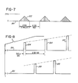
- Stimulator 50 generates a first signal 301 as illustrated by the top line of Fig. 8 and a second signal 302 as illustrated by the bottom line of Fig. 8.
- Signal 301 is applied across terminals 15a and 15c, while signal 302 is applied terminals 15b and 15c.
- Terminal 15c is connected to high voltage ground, as hereinafter described with reference to Fig. 5.
- Each of signals 301 and 302 has an envelope generally illustrated by triangular projections 303 rising above the line 300 of Fig. 7.
- the signal is characterized by alternating stimulation and rest periods of approximately 6 seconds each.
- the signal is pulsed at a frequency in a range from about 55 to 65 Hz and preferably about 60 Hz.
- the pulses which are so generated have peak values which increase gradually from a value near 0 volts to a maximum which is somewhat less than 255 volts and which produces maximum effort from the muscle or muscle group being stimulated. Thereafter the pulse amplitudes decrease gradually to a value near zero, and the muscle is rested.
- the maximum voltage value depends upon the state of exhaustion of the muscle and the effort which is desired. As the muscle tires, more stimulation voltage is required for production of the same effort. Generally speaking a maximum voltage of about 255 volts produces recruitment of all motor units and results in maximum effort by the muscle.
- signal 301 comprises a series of pulses 304 while signal 302 comprises another series of pulses 305.
- Pulses 304 and 305 are generated in an alternating sequence at a frequency of 60Hz each. Thus the effective combined frequency is 120Hz.
- Pulses 304 and 305 have peak values which conform with the signal enevelope of Fig. 7. They have a duration of approximately 500 microseconds, so that each of signals 301 and 302 has a duty cycle of 0.03. It has been found that if the pulse width is increased, then the stimulation voltage may be decreased and vice versa.
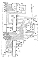
- circuitry for producing signals 301 and 302 is illustrated in Fig. 5.
- the associated feedback and control circuitry is illustrated schematically in Fig. 6.
- the circuitry includes integrated circuits as identified in Table I and components as identified in Table II. Table III lists significant pin number designations for the principal integrated circuits listed in Table I.
- IC 101 is connected to operate as a 60 Hz free running multivibrator.
- the output from IC 101 is. applied via transistor 104 to input pins 2 of IC 102 and 103.
- IC 102 and 103 produce alternating 500 microsecond pulses each at a frequency of 60 Hz for application to the collector terminals of transistors 105 and 106.
- the pulse width is set by appropriate selection of the resistance for resistors R116 and R124 and the capacitance of capacitors 117 and 125, as shown in the manufacturer's data sheets for integrated circuits 102 and 103.
- the phase between the pulses produced by integrated circuits 102 and 103 is set by appropriate selection of the resistance for resistors 113 and 114.
- Output voltage pulses from transformers 110 and 109 are applied to the base terminals of transistors 112 and 111 respectively.
- Transistors 112 and 111 provide a current gain so as to have high current, high voltage and low duty cycle pulses available for application across terminal pairs 15a-15c and 15b-15c.
- the analog driving signal appearing at line 197 is generated by the control system circuitry as illustrated in Fig. 6.
- the heart of the control system is the computer 13, which in the embodiment described herein is an APPLE II computer sold by Apple Computer Inc. of Cupertino, ' California.
- the APPLE II computer is provided with several slots into which may be plugged connectors for customized peripheral devices.
- the system described herein is plugged into slot number 3, which includes a connector 200 as illustrated by dotted lines in Fig. 6.
- the computer addresses analog .to digital converter 12 and digital to analog computer 13 through a decoder/demultiplexer 201.
- the peripheral board is addressed by the computer in memory locations C100 to C1FF (hexadecimal notation). Pin number 1 of connector 200 provides a signal from the computer's input/output select line.
- Pin number 1 is tied to pin number 5 of IC 201, an SN74LS138 integrated circuit.
- Pin number 5 is the G2 input of IC 201.
- a signal at this terminal enables IC 201 to decode the three high order bits (A7, A6, and A5) of an eight-bit address provided by the computer. These three bits appear at pin numbers 9, 8 and 7 respectively of connector 200.
- IC 201 is designed for producing eight decoded outputs, but only three of these outputs are used. These outputs appear at pin numbers 14, 12 and 10 and respectively read A/D converter 12, strobe D/A converter 14 and strobe A/D converter 12.
- A/D converter 12 is an eight channel device sold by National Semiconductor under the designation ADC0808. A/D converter 12 receives its clock from the system clock on pin number 40 of connector 200.
- A/D converter 12 When a strobe signal appears at pin number 12 of IC 201, A/D converter 12 is enabled for reading and digitizing analog signals appearing at any one of eight analog input ports (only two of which are used). The two analog input ports are addressed by a three-bit address appearing at pin numbers 25, 24 and 23 of A/D converter 12. The three address bits are the three least significant bits of an eight-bit address generated by computer 13. These three bits appear at pin numbers 2, 3 and 4 of'connector 200 (the three most significant bits appearing at pin numbers 7, 8 and 9 as above stated and bit numbers 3 and 4 not being utilized.
- Computer 13 generates the above mentioned eight-bit address whenever any one of computer memory address locations 50080 to 50087 (decimal notation) are strobed. Such strobing not only generates an associated eight-bit address, but also enables A/D converter 12 by causing generation of a strobe signal at output pin 12 of IC201, as above described.
- Memory locations 50080 to 50087 are strobed by execution of a "POKE" instruction, such as, for instance, the instruction "POKE 50080,0" appearing at line number 1450 of the computer program set forth in TABLE IV hereof.
- the described embodiment supplies only two analog input signals for digitizing by. A/D converter 12. These two signals appear at pin numbers 3 and 28 of A/D converter 12 and are addressed respectively by "POKING" memory locations 50080 and 50082 respectively. The resulting digitized representation thereof appears in eight-bit format at pin numbers 17, 14, 15, 8, 18, 19, 20 and 21 of A/D converter 12. These eight bits are read into memory location 49952 (decimal notation) upon execution of a "PEEK" instruction.
- A/D converter 12 is strobed to start conversion of the analog signal to digital format.
- a maximum of 100 microseconds is required for the analog to digital conversion, after which the computer may execute a normal memory read, cycle, whereby the digitized data is transferred onto the data bus and stored in memory location 49952.
- the output of A/D converter 12 is a eight-bit binary signal ranging between values of 0 and 255 (decimal) for analog input voltages between 0 and 5 volts.
- the analog signal supplied to pin No. 3 of A/D converter 12 has a triangular voltage profile and is produced by a profile generating circuit 202, comprising IC 204, amplifier 209, capacitors 219 and 220, and resistors 219 through 223.
- IC 204 generates a square wave at 1/6 Hz which is converted to a triangular ramp by capacitor 219 and resistor 221 and is buffered by amplifier 209.
- the triangular voltage profile,. so generated, represents a desired response from potentiometer 17 when the leg of the subject is being stimulated to raise and lower.
- potentiometer 17 is applied to pin No. 28 of A/D converter i2, as shown in Fig. 6.
- An output of 5 volts from potentiometer 17 represents a shaft angle rotation of 360°.
- the diameter of roller 38 is selected such that one rotation thereof corresponds to a leg movement of about 70 degrees from its initial vertial position.
- the amplitude of the analog stimulation signal appearing at line 197 is controlled by D/A converter 14, a DAC0831 integrated circuit sold by National Semiconductor. D/A converter 14 is selected for operation by applying a strobe signal to pin 19 thereof. Also, a write signal (logic LO) is applied to input terminals 1 and 2 for activating the transfer of data to the internal latch register of D/A converter 14. The data so transferred is an eight-bit stimulation command code appearing at terminals 13, 14, 15, 16, 4, 5, 6 and 7 of D/A converter 13. The output of D/A converter 14 is buffered and amplified and thereafter applied to input line 197 of stimulator 50.
- Computer 13 generates eight-bit binary representation of stimulation command voltages ranging between 0 and 255 by executing an appropriate POKE instruction.
- a desired stimulation voltage ranging between 0 and 255 is POKED into memory location 50016 (decimal).
- the computer When this memory location is POKED the computer generates an address for IC201 which causes output pin 12 to go LO.
- This LO output signal is inverted by inverter 205 to create the above mentioned strobe signal for D/A converter 14.
- the program set forth in TABLE IV includes an isometric strength measurement routine beginning at line 220 and a main control program beginning at line 1000.
- the main control program includes a start cycle beginning at line 1250 and a muscle stimulation routine beginning at line 1432.
- the start cycle finds the beginning of a ramp generated by the profile generator 202.
- the computer increments a variable Y from 1 to 17 (line 290) and POKES the value 10Y into memory location 50016. This causes generation of stimulation pulses having a voltage equal to the value 10Y.
- thetest supervisor depresses the Escape key on the computer control board. This action loads the ASCII code 155 into memory location 49152.
- the computer checks that memory location at line 329 and jumps to line 400 if the Escape key has been depressed. The computer then assigns the current value of 10Y to the variable Z as a threshold voltage.
- the computer enters the main control program to determine the maximum strength of the muscle by isokinetic exercise. During this routine the computer steps the stimulation voltage from the value Z up to 255 volts in 10 volt steps (lines 1045 and 1060). During this period of time the leg is attached to cable 34 as indicated by Fig. 3. When strength meter 36 indicates that the strength has leveled off, then the test supervisor again depresses the Escape key. The computer checks memory location 49152 once during each voltage step (line 1105) and proceeds to line 1120, if the Escape key has been depressed.
- the isokinetic exercise routine begins at line 1432. During this routine the computer generates stepped variations for a variable Z9 and POKES the value of Z9 into memory location 50016. After each new value of Z9 has been utilized for generation of a corresponding stimulation voltage, the computer checks to see if Z9 has a value equal to 255 (maximum stimulation voltage). If that value is noted, than the isokinetic exercise routine is terminated. If not, the computer proceeds to execute the instructions at line 1450 which cause reading of the analog voltages generated by profile generator 202 and potentiometer 17. These voltages are digitized and utilized to establish values for variables A8 and A9 respectively.
- A8 is greater than A9, the computer knows that the leg is not raised as much as it should be, and the value of Z9 is increased. This then increases the stimulation voltage command generated by the computer. Conversely, if A8 is less than A9, Z9 and the stimulation command are decreased. When A8 has decreased to a value indicating the end of a cycle, then the leg is rested for the duration of a counting loop which continues for approximately 6 seconds.
- a complete exercise procedure is therefore seen to include the following steps:
Landscapes
- Health & Medical Sciences (AREA)
- Physical Education & Sports Medicine (AREA)
- Engineering & Computer Science (AREA)
- Biomedical Technology (AREA)
- Nuclear Medicine, Radiotherapy & Molecular Imaging (AREA)
- Radiology & Medical Imaging (AREA)
- Life Sciences & Earth Sciences (AREA)
- Animal Behavior & Ethology (AREA)
- General Health & Medical Sciences (AREA)
- Public Health (AREA)
- Veterinary Medicine (AREA)
- Electrotherapy Devices (AREA)
- Percussion Or Vibration Massage (AREA)
Applications Claiming Priority (2)
| Application Number | Priority Date | Filing Date | Title |
|---|---|---|---|
| US06/417,935 US4480830A (en) | 1982-09-14 | 1982-09-14 | Method and apparatus for exercising |
| US417935 | 1989-10-06 |
Publications (2)
| Publication Number | Publication Date |
|---|---|
| EP0103490A2 true EP0103490A2 (fr) | 1984-03-21 |
| EP0103490A3 EP0103490A3 (fr) | 1987-03-18 |
Family
ID=23655964
Family Applications (1)
| Application Number | Title | Priority Date | Filing Date |
|---|---|---|---|
| EP83305388A Withdrawn EP0103490A3 (fr) | 1982-09-14 | 1983-09-14 | Appareil d'exercice |
Country Status (4)
| Country | Link |
|---|---|
| US (1) | US4480830A (fr) |
| EP (1) | EP0103490A3 (fr) |
| JP (1) | JPS59146669A (fr) |
| CA (1) | CA1209001A (fr) |
Cited By (4)
| Publication number | Priority date | Publication date | Assignee | Title |
|---|---|---|---|---|
| WO1986001733A1 (fr) * | 1984-09-20 | 1986-03-27 | Francis Berthelin | Installation de stimulation musculaire |
| EP0707467A4 (fr) * | 1993-07-09 | 1998-02-25 | Kinetecs Inc | Appareil et technique d'exercice |
| US5954621A (en) * | 1993-07-09 | 1999-09-21 | Kinetecs, Inc. | Exercise apparatus and technique |
| WO2003032887A1 (fr) * | 2001-10-19 | 2003-04-24 | The University Of Sydney | Systemes de stimulation musculaire ameliores |
Families Citing this family (35)
| Publication number | Priority date | Publication date | Assignee | Title |
|---|---|---|---|---|
| US4642769A (en) * | 1983-06-10 | 1987-02-10 | Wright State University | Method and apparatus for providing stimulated exercise of paralyzed limbs |
| US4582049A (en) * | 1983-09-12 | 1986-04-15 | Ylvisaker Carl J | Patient initiated response method |
| US4570927A (en) * | 1983-12-15 | 1986-02-18 | Wright State University | Therapeutic device |
| US4558704A (en) * | 1983-12-15 | 1985-12-17 | Wright State University | Hand control system |
| US4520827A (en) * | 1984-02-09 | 1985-06-04 | Empi, Inc. | NMS aided continuous passive motion apparatus |
| US4622973A (en) * | 1984-06-15 | 1986-11-18 | Empi, Inc. | Programmable functional electrical stimulation system |
| US4586495A (en) * | 1984-07-02 | 1986-05-06 | Wright State University | Therapy system for acute patient care |
| US4586510A (en) * | 1984-07-27 | 1986-05-06 | Wright State University | Apparatus for exercising a paralyzed limb |
| US4809696A (en) * | 1987-09-21 | 1989-03-07 | Hillcrest Medical Center | Functional electrical stimulation synchronizer switch |
| US4947836A (en) * | 1987-09-21 | 1990-08-14 | Hillcrest Medical Center | Exerciser with muscle stimulation |
| US5099828A (en) * | 1989-06-30 | 1992-03-31 | Duke Carl H | Passive exercise apparatus for entire body |
| JPH07227439A (ja) * | 1994-02-17 | 1995-08-29 | Konbi Kk | トレーニング装置 |
| US6393328B1 (en) * | 2000-05-08 | 2002-05-21 | International Rehabilitative Sciences, Inc. | Multi-functional portable electro-medical device |
| KR100375657B1 (ko) * | 2000-06-21 | 2003-03-15 | 주식회사 몸앤맘 | 체지방 제거장치 및 방법 |
| WO2002013696A1 (fr) * | 2000-08-14 | 2002-02-21 | Neopraxis Pty Ltd | Dispositif de mesure de la fatigue musculaire |
| CA2419317A1 (fr) * | 2000-08-14 | 2002-02-21 | Neopraxis Pty Ltd | Appareil d'exercice pour une personne souffrant de faiblesse musculaire |
| US20040172093A1 (en) * | 2003-01-31 | 2004-09-02 | Rummerfield Patrick D. | Apparatus for promoting nerve regeneration in paralyzed patients |
| US20060247095A1 (en) * | 2001-09-21 | 2006-11-02 | Rummerfield Patrick D | Method and apparatus for promoting nerve regeneration in paralyzed patients |
| US7035691B2 (en) * | 2002-01-15 | 2006-04-25 | Therapeutic Innovations, Inc. | Resonant muscle stimulator |
| CA2489767A1 (fr) * | 2002-06-18 | 2003-12-24 | University Of Iowa Research Foundation | Methode et systeme d'exercice therapeutique destine a un systeme d'entrainement neuromusculosquelettique paralyse et non paralyse |
| US6876883B2 (en) | 2002-08-26 | 2005-04-05 | Arthur F. Hurtado | Method for applying variable electro-muscle stimulation and system therefor |
| US20060247733A1 (en) * | 2005-05-02 | 2006-11-02 | Salah Amer | Garment for electrical muscle stimulation of muscles in the upper body and arms and legs |
| US7801600B1 (en) * | 2005-05-26 | 2010-09-21 | Boston Scientific Neuromodulation Corporation | Controlling charge flow in the electrical stimulation of tissue |
| US8249714B1 (en) | 2005-07-08 | 2012-08-21 | Customkynetics, Inc. | Lower extremity exercise device with stimulation and related methods |
| ES2354387T3 (es) * | 2005-08-12 | 2011-03-14 | Vupiesse Italia S.R.L. | Dispositivo portátil para autoenfrentamiento de músculos abdominales. |
| US20070208392A1 (en) * | 2006-02-17 | 2007-09-06 | Alfred E. Mann Foundation For Scientific Research | System for functional electrical stimulation |
| JP4839163B2 (ja) * | 2006-09-14 | 2011-12-21 | テルモ株式会社 | 電気刺激による脚運動装置 |
| EP2318093B1 (fr) * | 2008-07-02 | 2019-11-13 | Sage Products, LLC | Systèmes de stimulation musculaire automatique |
| US8892210B2 (en) | 2008-07-02 | 2014-11-18 | Niveus Medical, Inc. | Devices, systems, and methods for automated optimization of energy delivery |
| US8265763B2 (en) * | 2008-08-26 | 2012-09-11 | Niveus Medical, Inc. | Device, system, and method to improve powered muscle stimulation performance in the presence of tissue edema |
| US9149386B2 (en) | 2008-08-19 | 2015-10-06 | Niveus Medical, Inc. | Devices and systems for stimulation of tissues |
| CA2751527C (fr) | 2009-02-20 | 2020-05-05 | Niveus Medical, Inc. | Systemes et procedes de stimulation musculaire electrique a l'aide d'un champ de guidage d'energie |
| US8588901B2 (en) | 2009-11-11 | 2013-11-19 | Niveus Medical, Inc. | Synergistic muscle activation device |
| US9114255B1 (en) | 2011-06-17 | 2015-08-25 | Customkynetics, Inc. | Exercise device for use with electrical stimulation and related methods |
| JP6276500B2 (ja) * | 2012-11-22 | 2018-02-07 | 株式会社ナカメ | ダイエットシステム |
Family Cites Families (28)
| Publication number | Priority date | Publication date | Assignee | Title |
|---|---|---|---|---|
| US1498529A (en) * | 1921-11-21 | 1924-06-24 | James B Allen | Exercising machine |
| US2630115A (en) * | 1951-11-03 | 1953-03-03 | Bierman William | Exerciser for subnormal muscles |
| FR1139319A (fr) * | 1955-09-10 | 1957-06-27 | Appareil électrothérapeutique régularisant et normalisant les contractions musculaires | |
| US2815020A (en) * | 1955-09-16 | 1957-12-03 | Barkschat Eric | Automatic exerciser for feet and legs |
| US3000632A (en) * | 1959-05-15 | 1961-09-19 | Anthony A Fuchs | Exercising device |
| US3083712A (en) * | 1961-11-29 | 1963-04-02 | Heinicke Instr Co Inc | Device for producing electrical muscle trerapy |
| US3204637A (en) * | 1963-02-07 | 1965-09-07 | Erich J Frank | Stimulating apparatus |
| US3344792A (en) * | 1965-01-13 | 1967-10-03 | Franklin F Offner | Method of muscular stimulation in human beings to aid in walking |
| US3387147A (en) * | 1967-06-09 | 1968-06-04 | Dynatone Electronics Corp | Muscle stimulating pulse generator |
| GB1227186A (fr) * | 1968-09-18 | 1971-04-07 | ||
| US3817254A (en) * | 1972-05-08 | 1974-06-18 | Medtronic Inc | Transcutaneous stimulator and stimulation method |
| US3848467A (en) * | 1972-07-10 | 1974-11-19 | E Flavell | Proportioned resistance exercise servo system |
| US4148321A (en) * | 1973-11-26 | 1979-04-10 | Wyss Oscar A M | Apparatuses and methods for therapeutic treatment and active massages of muscles |
| US3911910A (en) * | 1974-05-31 | 1975-10-14 | Robert J Oesau | Electro-splint for relieving involuntary muscular spasticity |
| SU635935A1 (ru) * | 1974-12-08 | 1978-12-05 | Центральный Научно-Исследовательский И Проектно-Технологический Институт Механизации И Электрификации Животноводства Южной Зоны Ссср | Устройство дл выдачи корма животным в зависимости от надо молока |
| US3929335A (en) * | 1975-02-10 | 1975-12-30 | Franklin S Malick | Electronic exercise aid |
| US3989240A (en) * | 1975-05-06 | 1976-11-02 | Victor Bernard J | Electrically timed exercising device |
| US4256302A (en) * | 1976-03-10 | 1981-03-17 | Keiser Dennis L | Variable resistance exercising device |
| US4071033A (en) * | 1976-12-20 | 1978-01-31 | Nawracaj Edward P | Electrotherapeutic device with modulated dual signals |
| US4257590A (en) * | 1977-08-26 | 1981-03-24 | Javier R. Ruiz | Portable home gymnasium |
| SU719635A1 (ru) * | 1978-01-30 | 1980-03-05 | Центральный Ордена Трудового Красного Знамени Научно-Исследовательский Институт Протезирования И Протезостроения | Электростимул тор мышц |
| US4165750A (en) * | 1978-03-18 | 1979-08-28 | Aleev Leonid S | Bioelectrically controlled electric stimulator of human muscles |
| US4177819A (en) * | 1978-03-30 | 1979-12-11 | Kofsky Harvey I | Muscle stimulating apparatus |
| SE417476B (sv) * | 1978-07-25 | 1981-03-23 | Storvreta Sport Ab | Benkanordning for muskelkraftmetning |
| US4284157A (en) * | 1978-12-01 | 1981-08-18 | Lay Larry D | Vehicle for the physically handicapped |
| US4305402A (en) * | 1979-06-29 | 1981-12-15 | Katims Jefferson J | Method for transcutaneous electrical stimulation |
| DE3030897A1 (de) * | 1980-08-14 | 1982-03-18 | Anna Stanec | Verfahren und vorrichtung zur ermittlung der isometrischen spannung am adductor-pollicis-muskel des menschlichen daumes |
| US4392496A (en) * | 1981-03-13 | 1983-07-12 | Medtronic, Inc. | Neuromuscular stimulator |
-
1982
- 1982-09-14 US US06/417,935 patent/US4480830A/en not_active Expired - Lifetime
-
1983
- 1983-08-26 CA CA000435410A patent/CA1209001A/fr not_active Expired
- 1983-09-14 JP JP58170540A patent/JPS59146669A/ja active Granted
- 1983-09-14 EP EP83305388A patent/EP0103490A3/fr not_active Withdrawn
Cited By (5)
| Publication number | Priority date | Publication date | Assignee | Title |
|---|---|---|---|---|
| WO1986001733A1 (fr) * | 1984-09-20 | 1986-03-27 | Francis Berthelin | Installation de stimulation musculaire |
| EP0707467A4 (fr) * | 1993-07-09 | 1998-02-25 | Kinetecs Inc | Appareil et technique d'exercice |
| US5954621A (en) * | 1993-07-09 | 1999-09-21 | Kinetecs, Inc. | Exercise apparatus and technique |
| US5980435A (en) * | 1993-07-09 | 1999-11-09 | Kinetecs, Inc. | Methods of therapy or controlled exercise using a jointed brace |
| WO2003032887A1 (fr) * | 2001-10-19 | 2003-04-24 | The University Of Sydney | Systemes de stimulation musculaire ameliores |
Also Published As
| Publication number | Publication date |
|---|---|
| US4480830A (en) | 1984-11-06 |
| CA1209001A (fr) | 1986-08-05 |
| EP0103490A3 (fr) | 1987-03-18 |
| JPS59146669A (ja) | 1984-08-22 |
| JPH0376951B2 (fr) | 1991-12-09 |
Similar Documents
| Publication | Publication Date | Title |
|---|---|---|
| EP0103491B1 (fr) | Procédé et appareil pour stimulation des muscles avec contrôle à réaction | |
| EP0103490A2 (fr) | Appareil d'exercice | |
| US4556214A (en) | Method and apparatus for exercising | |
| Alon | High voltage stimulation: effects of electrode size on basic excitatory responses | |
| Kelly | Factors influencing quadriceps femoris muscle torque using transcutaneous neuromuscular electrical stimulation | |
| US4586495A (en) | Therapy system for acute patient care | |
| US4838272A (en) | Method and apparatus for adaptive closed loop electrical stimulation of muscles | |
| US9669211B2 (en) | Method and apparatus for applying neuromuscular electrical stimulation | |
| EP0111229B1 (fr) | Dispositif pour la stimulation électrique des nerfs | |
| US4723552A (en) | Transcutaneous electrical nerve stimulation device | |
| US4640286A (en) | Optimized nerve fiber stimulation | |
| US7174215B2 (en) | Method for determining stimulation parameters | |
| US8175713B1 (en) | Electro-stimulation device to pump blood from legs | |
| US20030208246A1 (en) | Electrostimulation system with electromyographic and visual biofeeback | |
| SE9603635D0 (sv) | Implantable stimulator | |
| JP2002113115A (ja) | バリアント方式を利用した電気治療装置 | |
| DE2965791D1 (en) | Apparatus for tachycardia investigation or control | |
| Carson et al. | Electromyographic activity, H-reflex modulation and corticospinal input to forearm motoneurones during active and passive rhythmic movements | |
| Katz et al. | Facilitation of soleus‐coupled Renshaw cells during voluntary contraction of pretibial flexor muscles in man. | |
| DE DOMENICO et al. | Motor stimulation with interferential currents | |
| Popp | Design and construction of a laboratory system for neuromuscular stimulation of the lower extremities during cycling | |
| SU635995A1 (ru) | Способ стимул ции нервно-мышечного аппарата | |
| Daskalov et al. | Electrical stimulation of innervated muscles | |
| CA1313539C (fr) | Stimulation des fibres nerveuses a l'aide d'electrodes multiples egalement actives | |
| Guttenberg et al. | 16-channel stimulation systems for the use of FES and related applications |
Legal Events
| Date | Code | Title | Description |
|---|---|---|---|
| PUAI | Public reference made under article 153(3) epc to a published international application that has entered the european phase |
Free format text: ORIGINAL CODE: 0009012 |
|
| AK | Designated contracting states |
Designated state(s): CH DE FR GB IT LI NL SE |
|
| PUAL | Search report despatched |
Free format text: ORIGINAL CODE: 0009013 |
|
| AK | Designated contracting states |
Kind code of ref document: A3 Designated state(s): CH DE FR GB IT LI NL SE |
|
| 17P | Request for examination filed |
Effective date: 19870910 |
|
| STAA | Information on the status of an ep patent application or granted ep patent |
Free format text: STATUS: THE APPLICATION HAS BEEN WITHDRAWN |
|
| 18W | Application withdrawn |
Withdrawal date: 19881127 |
|
| RIN1 | Information on inventor provided before grant (corrected) |
Inventor name: PETROFSKY, STEVEN H. Inventor name: PETROFSKY, JERROLD S. Inventor name: GLASER, ROGER M. Inventor name: HEATON, HARRY H. III |