EP0103422B1 - Measurement of oscillatory and vibrational motion - Google Patents
Measurement of oscillatory and vibrational motion Download PDFInfo
- Publication number
- EP0103422B1 EP0103422B1 EP83304747A EP83304747A EP0103422B1 EP 0103422 B1 EP0103422 B1 EP 0103422B1 EP 83304747 A EP83304747 A EP 83304747A EP 83304747 A EP83304747 A EP 83304747A EP 0103422 B1 EP0103422 B1 EP 0103422B1
- Authority
- EP
- European Patent Office
- Prior art keywords
- beams
- light
- points
- frequency
- shaft
- Prior art date
- Legal status (The legal status is an assumption and is not a legal conclusion. Google has not performed a legal analysis and makes no representation as to the accuracy of the status listed.)
- Expired
Links
- 230000033001 locomotion Effects 0.000 title claims description 17
- 238000005259 measurement Methods 0.000 title description 2
- 230000003534 oscillatory effect Effects 0.000 title 1
- 238000000034 method Methods 0.000 claims description 23
- 230000003287 optical effect Effects 0.000 claims description 6
- 230000001427 coherent effect Effects 0.000 claims description 5
- 238000000926 separation method Methods 0.000 claims description 5
- 230000001419 dependent effect Effects 0.000 claims description 3
- 238000012544 monitoring process Methods 0.000 claims description 3
- 239000000523 sample Substances 0.000 description 5
- 239000007787 solid Substances 0.000 description 4
- 238000010586 diagram Methods 0.000 description 3
- 230000000694 effects Effects 0.000 description 2
- CPBQJMYROZQQJC-UHFFFAOYSA-N helium neon Chemical compound [He].[Ne] CPBQJMYROZQQJC-UHFFFAOYSA-N 0.000 description 2
- 239000003973 paint Substances 0.000 description 1
- 230000000737 periodic effect Effects 0.000 description 1
Images
Classifications
-
- G—PHYSICS
- G01—MEASURING; TESTING
- G01H—MEASUREMENT OF MECHANICAL VIBRATIONS OR ULTRASONIC, SONIC OR INFRASONIC WAVES
- G01H1/00—Measuring characteristics of vibrations in solids by using direct conduction to the detector
- G01H1/10—Measuring characteristics of vibrations in solids by using direct conduction to the detector of torsional vibrations
-
- G—PHYSICS
- G01—MEASURING; TESTING
- G01H—MEASUREMENT OF MECHANICAL VIBRATIONS OR ULTRASONIC, SONIC OR INFRASONIC WAVES
- G01H9/00—Measuring mechanical vibrations or ultrasonic, sonic or infrasonic waves by using radiation-sensitive means, e.g. optical means
-
- G—PHYSICS
- G01—MEASURING; TESTING
- G01P—MEASURING LINEAR OR ANGULAR SPEED, ACCELERATION, DECELERATION, OR SHOCK; INDICATING PRESENCE, ABSENCE, OR DIRECTION, OF MOVEMENT
- G01P3/00—Measuring linear or angular speed; Measuring differences of linear or angular speeds
- G01P3/36—Devices characterised by the use of optical means, e.g. using infrared, visible, or ultraviolet light
-
- G—PHYSICS
- G01—MEASURING; TESTING
- G01S—RADIO DIRECTION-FINDING; RADIO NAVIGATION; DETERMINING DISTANCE OR VELOCITY BY USE OF RADIO WAVES; LOCATING OR PRESENCE-DETECTING BY USE OF THE REFLECTION OR RERADIATION OF RADIO WAVES; ANALOGOUS ARRANGEMENTS USING OTHER WAVES
- G01S17/00—Systems using the reflection or reradiation of electromagnetic waves other than radio waves, e.g. lidar systems
- G01S17/02—Systems using the reflection of electromagnetic waves other than radio waves
- G01S17/50—Systems of measurement based on relative movement of target
- G01S17/58—Velocity or trajectory determination systems; Sense-of-movement determination systems
Definitions
- the present invention relates to a method and apparatus for continuously monitoring the instantaneous movement of a surface whose motion is non-uniform and for measuring torsional vibrations in rotary machine parts, in particular, to optical heterodyne methods and apparatus.
- this method is time-consuming and cannot be used where access to the shaft is restricted and there is not sufficient room for the slotted disc to be mounted on the shaft. Furthermore, this method has a limited frequency response over the frequency ranges which are of interest.
- a beam from a laser source is split, in a conventional manner, to form two parallel beams which are focused by a lens so that they intersect at the surface of the rotating shaft.
- the frequency of the light which is backscattered at the surface of the shaft is Doppler shifted because the shaft surface is moving.
- the two laser beams are coherent, the backscattered light from the two beams heterodynes at a detector positioned to receive it and the detected intensity is modulated at a frequency which is a function of the speed at which the surface is moving. Consequently, variations in the modulation frequency as the shaft revolves provide an indication of the level of torsional vibration.
- this device avoids the need for mounting slip rings or slotted discs on the shaft, it has a number of disadvantages.
- the velocimeter must be arranged so that the shaft surface lies within the region where the beams intersect. As this region is generally only a fraction of a millimetre in length, accurate positioning of the device is necessary and hand-held use is not possible.
- this method is, of course restricted to shafts of circular cross-section. Again, in circumstances where access to the shaft is restricted, it may not be possible to position the device so that the intersection of the beams occurs at the shaft surface at all. It is also desirable that the modulation frequency should be within the frequency range for which the electronic circuitry used to process the detector output gives an optimum response.
- the modulation frequency is critically dependent on the speed of movement of the shaft surface and the velocimeter cannot, therefore, easily be used to measure a very wide range of speeds.
- the only other factors on which the modulation frequency is dependent are the wavelength of the laser light and the angle at which the beams intersect. Neither of these can easily be varied to adjust the modulation frequency.
- the cross-beam velocimeter is also susceptible to lateral movement of the shaft and provides an incorrect indication of the speed of movement of the shaft surface if the axial motion of the shaft has a velocity component in the plane defined by the incident laser beams.
- WO-A-8103073 Another type of optical heterodyne method is described in WO-A-8103073.
- the method described in the document utilises a beam from a laser light source which is split to form a probe beam and a reference beam.
- the reference beam passes directly to a photodetector.
- the probe beam is directed onto a moving surface.
- Light reflected or backscattered along the incident probe beam direction reaches the photodetector after being reflected from the outcoupling element of the laser source and is heterodyned with the reference beam.
- the output from the detector gives an indication of the speed of movement of the surface along the direction of the incident probe beam.
- the document suggests that two or three probe beams be used, each incident on the moving surface from a different direction and providing a signal indicative of the surface speed in the direction of the incident beam.
- the beam of the invention is characterised in that two spaced parallel beams of coherent light are directed onto the said surface and the light backscattered along the beam axes from the points at which the two beams are incident on the said surface is heterodyned together and the modulation frequency of the heterodyned backscattered light is measured; the modulation frequency of the heterdyned backscattered light being a measure for the difference of the velocities of the surface at the two said points.
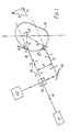
- Fig. 1 The arrangement shown in Fig. 1 is used to measure torsional vibrations, that is variations in the speed of rotation, of a rotary shaft 10 of arbitrary cross-section, for example, in the case of conventional shaft, of circular cross-section.
- the shaft 10 rotates about its axis 12 and also experiences an instantaneous lateral movement at a velocity vector U.
- the beam 16 from a laser light source 14 is directed towards the surface of the shaft 10 and is split, in a conventional manner, by means of a 50% transmission-reflection beamsplitter 18 and a mirror 20 to form two parallel beams 16 and 17, separated by a distance d, which strike the surface of the shaft 10 at points A and B respectively.
- the rotation of the shaft 10 about the axis 12 is such that its surface moves with nominal tangential velocities V, and V 2 at points A and B respectively.
- the laser light source 14 may, for example, be a helium-neon laser.
- the source used may have a low power output in order to comply with safety regulations and a typical output would be of the order of 2 milliwatts so that, after splitting, each beam seen by the user has a power output of not more than 1 milliwatt.
- One suitable helium-neon laser light source is that manufactured by Hughes Ltd., of Carlsbad, California, U.S.A.
- the beam- splitter 18 and mirror 20 may be of any conventional type and may be replaced with a number of other conventional arrangements for providing two parallel laser beams, the separation of which can be varied.
- the frequency of the light scattered by the surface at the points A and B is Doppler shifted.
- the light which is backscattered along the axes of the incident beams 16 and 17 is collected through four masks 19 which strictly define the solid angle of backscattered light which is collected.
- the collected light is mixed at the beam-splitter 18 before being received by a photo-detector 22.
- the surface of the shaft 10 may be treated with retro-reflective tape or paint.
- the photodetector 22 is a photomultiplier, for example, the Type 965 8B photomultiplier manufactured by EMI Limited, of 20 Manchester Square, London, W1 or a solid state photodiode. For compactness, it is preferred to use a solid state device.
- the shift in the frequency of the light backscattered along the incident beam axis at point A, F A is given by where p is the refractive index of air, ⁇ is the wavelength of the laser light used, 8 is the angle between the axis of incident laser beam 16 and the direction of motion of the shaft surface at point A and U, is the component of the lateral velocity of the shaft 10 along the direction of the beam 16.
- the frequency at which the detected light intensity is modulated is directly proportional to the rotational speed of the body. If the modulation frequency is monitored over a period of time, variations in the modulation frequency will, therefore provide an accurate indication of the level of torsional vibration in the shaft.
- This method has a number of advantages over that employed in the cross-beam laser-Doppler velocimeter described above.
- the distance from the laser source to the shaft surface can easily be varied because the beams used are parallel and there is no need to position the source so that the shaft surface lies within the small region in which the beams intersect.
- the parallel beam arrangement is insensitive to lateral and axial movement of the shaft and consequently the method can successfully utilize a hand-held laser source and detector.
- tilting does affect the output of the device, body movement only introduces frequencies of 30 Hz and less and, as these are often considerably lower than the vibrational frequencies of interest, the low frequency signals can, if necessary be filtered out.
- the photodetector output can be processed using a commercially available Doppler frequency tracker or using a ratemeter which is essentially a zero-crossing counter which can convert the Doppler frequency to an analogue voltage.
- the ratemeter output is gated so that, if the photodetector output amplitude drops below a threshold level due to amplitude modulation caused by "speckle" effects, that is, effects due to phase differences between light scattered from points A and B, the ratemeter output remains at the last frequency value which occured before the drop.
- the gating causes "flats" in the detected Doppler frequency but the flats are in practice very short compared to the vibrational frequencies which are to be measured and the flats simply contribute to the instrument noise level.
- the modulation frequency can be adjusted to suit the electronic circuitry used to process the detector output simply by altering the separation of the beams 16 and 17. This may be done, for example, by moving the mirror 20 towards or away from the beamsplitter 18. In some circumstances, it is desirable that the modulation frequency should have a non-zero value when the shaft is stationary. This can be achieved by introducing a frequency shifting device, for example, a diffraction grating or a Bragg cell, in a conventional manner into the path of one of the beams 16 and 17 so that its frequency is pre- shifted by a fixed amount relative to the other.
- a frequency shifting device for example, a diffraction grating or a Bragg cell
- the beams are directed onto the surface of the shaft 10
- Using the end surface of the shaft introduces a cosine factor into the relationship between the Doppler frequency and rotational speed of the shaft. Consequently, when the device is hand held, tilting will introduce spurious variations in the Doppler frequency due to variations in the cosine factor but, again, only at frequencies at 30 Hz or less.
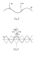
- the same optical apparatus can be used to measure the phase difference between two points along a travelling wave as indicated in Fig. 2.
- a travelling wave may be set up in the solid surface 40 of a machine part by, for example, periodic contact with another machine component. If the optical arrangement described above in relation to Fig. 1 is used to direct parallel laser beams 42 and 44 onto the surface 40 so that they strike the surface at points C and D respectively, the light scattered at points C and D is Doppler shifted because the surface 40 is moving. Provided that points C and D are not exactly in phase, the linear velocities of the surface 40 at points C and D differ at any given time and the frequency of the light scattered at points C and D is shifted by different amounts. As described above, the light received by the detector (not shown) heterodynes and the frequency of the detected intensity modulation is a measure of the phase difference between points C and D along the wave. When the modulation frequency is zero, points C and D are exactly in phase and the beam separation, d, is equal to an integral number of wavelengths. Phasemeters of this kind are useful in identifying the vibration power flow through structures.
- the instrument can only be used when a single frequency travelling wave is present. When several waves are present, the situation is more complex but the instrument can still be used in modal analysis. When several travelling waves interfere in a continuously vibrating structure a well-defined modal pattern of nodes and anti-nodes may occur. The instrument may be used, as shown in Fig. 3 to identify the anti-nodes.
- Two parallel laser beams 50 and 52 produced by the optical arrangement described in relation to Fig. 1 are directed onto a vibrating surface 54 so that they are incident on the surface at points E and F. If points E and F are symmetrically disposed about a vibrational anti-node, the surface at both points E and F moves at the same speed and in the same direction and the frequencies of both beams 50 and 52 are Doppler shifted by the same amount. Consequently, the modulation frequency at the detector is zero. If points E and F are not symmetrical about an anti-node the detected frequency takes on a positive value. Thus, the instrument can be used to identify the anti-nodes of the modal pattern by passing the beams over the surface and identifying those points at which the detected frequency drops to zero.
- the method described above can, in general, be used to measure the difference in velocity at two points on any surface. It can, therefore, be used to characterise any vibrational motion.
Landscapes
- Physics & Mathematics (AREA)
- General Physics & Mathematics (AREA)
- Electromagnetism (AREA)
- Engineering & Computer Science (AREA)
- Computer Networks & Wireless Communication (AREA)
- Radar, Positioning & Navigation (AREA)
- Remote Sensing (AREA)
- Power Engineering (AREA)
- Measurement Of Mechanical Vibrations Or Ultrasonic Waves (AREA)
Description
- The present invention relates to a method and apparatus for continuously monitoring the instantaneous movement of a surface whose motion is non-uniform and for measuring torsional vibrations in rotary machine parts, in particular, to optical heterodyne methods and apparatus.
- If vibrations are not sufficiently controlled they lead very quickly to fatigue failure of the rotary parts. There is, therefore, a need for apparatus capable of detecting and measuring reliably torsional vibrations in rotary machine parts. Existing methods for measuring such vibrations in rotating shafts involve the use of slip rings or slotted discs which are physically mounted on the shaft. Using slotted discs, a transducer monitors the number of slots which pass it in each revolution of the shaft and variations in the rate at which the slots reach the transducer over a period of time provide an indication of the level of torsional vibration in the shaft. As it is necessary to mount the slotted. disc on the shaft each time a measurement is to be made, this method is time-consuming and cannot be used where access to the shaft is restricted and there is not sufficient room for the slotted disc to be mounted on the shaft. Furthermore, this method has a limited frequency response over the frequency ranges which are of interest.
- One known device which utilizes a non-contact method and which overcomes some of these disadvantages is the cross beam laser-Doppler velocimeter. A beam from a laser source is split, in a conventional manner, to form two parallel beams which are focused by a lens so that they intersect at the surface of the rotating shaft. The frequency of the light which is backscattered at the surface of the shaft is Doppler shifted because the shaft surface is moving. As the two laser beams are coherent, the backscattered light from the two beams heterodynes at a detector positioned to receive it and the detected intensity is modulated at a frequency which is a function of the speed at which the surface is moving. Consequently, variations in the modulation frequency as the shaft revolves provide an indication of the level of torsional vibration.
- Although this device avoids the need for mounting slip rings or slotted discs on the shaft, it has a number of disadvantages. The velocimeter must be arranged so that the shaft surface lies within the region where the beams intersect. As this region is generally only a fraction of a millimetre in length, accurate positioning of the device is necessary and hand-held use is not possible. Furthermore, this method is, of course restricted to shafts of circular cross-section. Again, in circumstances where access to the shaft is restricted, it may not be possible to position the device so that the intersection of the beams occurs at the shaft surface at all. It is also desirable that the modulation frequency should be within the frequency range for which the electronic circuitry used to process the detector output gives an optimum response. The modulation frequency is critically dependent on the speed of movement of the shaft surface and the velocimeter cannot, therefore, easily be used to measure a very wide range of speeds. The only other factors on which the modulation frequency is dependent are the wavelength of the laser light and the angle at which the beams intersect. Neither of these can easily be varied to adjust the modulation frequency. The cross-beam velocimeter is also susceptible to lateral movement of the shaft and provides an incorrect indication of the speed of movement of the shaft surface if the axial motion of the shaft has a velocity component in the plane defined by the incident laser beams.
- Another type of optical heterodyne method is described in WO-A-8103073. The method described in the document utilises a beam from a laser light source which is split to form a probe beam and a reference beam. The reference beam passes directly to a photodetector. The probe beam is directed onto a moving surface. Light reflected or backscattered along the incident probe beam direction reaches the photodetector after being reflected from the outcoupling element of the laser source and is heterodyned with the reference beam. The output from the detector gives an indication of the speed of movement of the surface along the direction of the incident probe beam. In order to give a more complete indication of the surface velocity, the document suggests that two or three probe beams be used, each incident on the moving surface from a different direction and providing a signal indicative of the surface speed in the direction of the incident beam.
- The beam of the invention is characterised in that two spaced parallel beams of coherent light are directed onto the said surface and the light backscattered along the beam axes from the points at which the two beams are incident on the said surface is heterodyned together and the modulation frequency of the heterodyned backscattered light is measured; the modulation frequency of the heterdyned backscattered light being a measure for the difference of the velocities of the surface at the two said points.
- Embodiments of the invention will now be described in detail, by way of example, with reference to the drawings, in which:
- Fig. 1 is a diagram illustrating a method of measuring torsional vibration in accordance with the invention;
- Fig. 2 is a diagram illustrating a method of measuring phase differences in accordance with the invention; and
- Fig. 3 is a schematic diagram illustrating a method of modal analysis in accordance with the invention.
- The arrangement shown in Fig. 1 is used to measure torsional vibrations, that is variations in the speed of rotation, of a
rotary shaft 10 of arbitrary cross-section, for example, in the case of conventional shaft, of circular cross-section. Theshaft 10 rotates about itsaxis 12 and also experiences an instantaneous lateral movement at a velocity vector U. - The
beam 16 from alaser light source 14 is directed towards the surface of theshaft 10 and is split, in a conventional manner, by means of a 50% transmission-reflection beamsplitter 18 and amirror 20 to form twoparallel beams 16 and 17, separated by a distance d, which strike the surface of theshaft 10 at points A and B respectively. The rotation of theshaft 10 about theaxis 12 is such that its surface moves with nominal tangential velocities V, and V2 at points A and B respectively. - The
laser light source 14 may, for example, be a helium-neon laser. The source used may have a low power output in order to comply with safety regulations and a typical output would be of the order of 2 milliwatts so that, after splitting, each beam seen by the user has a power output of not more than 1 milliwatt. One suitable helium-neon laser light source is that manufactured by Hughes Ltd., of Carlsbad, California, U.S.A. The beam-splitter 18 andmirror 20 may be of any conventional type and may be replaced with a number of other conventional arrangements for providing two parallel laser beams, the separation of which can be varied. - As the surface of the
shaft 10 is moving, the frequency of the light scattered by the surface at the points A and B is Doppler shifted. The light which is backscattered along the axes of theincident beams 16 and 17 is collected through fourmasks 19 which strictly define the solid angle of backscattered light which is collected. The collected light is mixed at the beam-splitter 18 before being received by a photo-detector 22. In order to ensure that a sufficient amount of light is backscattered to thephotodetector 22, the surface of theshaft 10 may be treated with retro-reflective tape or paint. - Typically, the
photodetector 22 is a photomultiplier, for example, the Type 965 8B photomultiplier manufactured by EMI Limited, of 20 Manchester Square, London, W1 or a solid state photodiode. For compactness, it is preferred to use a solid state device. - The shift in the frequency of the light backscattered along the incident beam axis at point A, FA, is given by

incident laser beam 16 and the direction of motion of the shaft surface at point A and U, is the component of the lateral velocity of theshaft 10 along the direction of thebeam 16. - Similarly, the shift in the frequency of the light backscattered along the incident beam axis of point B, FB, is given by

- Light which is backscattered from the points A and B along the directions of the
incident beams 16 and 17 is directed into thephotodetector 22. As the light emitted by thelaser 14 is coherent and essentially single frequency, the backscattered light from points A and B heterodynes at thedetector 22 and the detected light intensity is modulated at a frequency F given by

rotation 12 and N is the rotational speed in r.p.m. Further
incident beams 16 and 17. Consequently
- From this, it can be seen that the frequency at which the detected light intensity is modulated is directly proportional to the rotational speed of the body. If the modulation frequency is monitored over a period of time, variations in the modulation frequency will, therefore provide an accurate indication of the level of torsional vibration in the shaft.
- This method has a number of advantages over that employed in the cross-beam laser-Doppler velocimeter described above. The distance from the laser source to the shaft surface can easily be varied because the beams used are parallel and there is no need to position the source so that the shaft surface lies within the small region in which the beams intersect. The parallel beam arrangement is insensitive to lateral and axial movement of the shaft and consequently the method can successfully utilize a hand-held laser source and detector.
- Although tilting does affect the output of the device, body movement only introduces frequencies of 30 Hz and less and, as these are often considerably lower than the vibrational frequencies of interest, the low frequency signals can, if necessary be filtered out.
- The photodetector output can be processed using a commercially available Doppler frequency tracker or using a ratemeter which is essentially a zero-crossing counter which can convert the Doppler frequency to an analogue voltage. The ratemeter output is gated so that, if the photodetector output amplitude drops below a threshold level due to amplitude modulation caused by "speckle" effects, that is, effects due to phase differences between light scattered from points A and B, the ratemeter output remains at the last frequency value which occured before the drop. The gating causes "flats" in the detected Doppler frequency but the flats are in practice very short compared to the vibrational frequencies which are to be measured and the flats simply contribute to the instrument noise level.
- The modulation frequency can be adjusted to suit the electronic circuitry used to process the detector output simply by altering the separation of the
beams 16 and 17. This may be done, for example, by moving themirror 20 towards or away from thebeamsplitter 18. In some circumstances, it is desirable that the modulation frequency should have a non-zero value when the shaft is stationary. This can be achieved by introducing a frequency shifting device, for example, a diffraction grating or a Bragg cell, in a conventional manner into the path of one of thebeams 16 and 17 so that its frequency is pre- shifted by a fixed amount relative to the other. - Although, in the arrangement shown in the drawings, the beams are directed onto the surface of the
shaft 10, it is also possible to direct the beams onto the radial end surface of the shaft. Using the end surface of the shaft introduces a cosine factor into the relationship between the Doppler frequency and rotational speed of the shaft. Consequently, when the device is hand held, tilting will introduce spurious variations in the Doppler frequency due to variations in the cosine factor but, again, only at frequencies at 30 Hz or less. - The same optical apparatus can be used to measure the phase difference between two points along a travelling wave as indicated in Fig. 2.
- A travelling wave may be set up in the
solid surface 40 of a machine part by, for example, periodic contact with another machine component. If the optical arrangement described above in relation to Fig. 1 is used to directparallel laser beams surface 40 so that they strike the surface at points C and D respectively, the light scattered at points C and D is Doppler shifted because thesurface 40 is moving. Provided that points C and D are not exactly in phase, the linear velocities of thesurface 40 at points C and D differ at any given time and the frequency of the light scattered at points C and D is shifted by different amounts. As described above, the light received by the detector (not shown) heterodynes and the frequency of the detected intensity modulation is a measure of the phase difference between points C and D along the wave. When the modulation frequency is zero, points C and D are exactly in phase and the beam separation, d, is equal to an integral number of wavelengths. Phasemeters of this kind are useful in identifying the vibration power flow through structures. - When the instrument is to be used as a phasemeter, it is generally desirable to pre-shift the frequency of one of the beams as described as above so that zero surface movement still produces a heterodyne frequency.
- The instrument can only be used when a single frequency travelling wave is present. When several waves are present, the situation is more complex but the instrument can still be used in modal analysis. When several travelling waves interfere in a continuously vibrating structure a well-defined modal pattern of nodes and anti-nodes may occur. The instrument may be used, as shown in Fig. 3 to identify the anti-nodes.
- Two
parallel laser beams surface 54 so that they are incident on the surface at points E and F. If points E and F are symmetrically disposed about a vibrational anti-node, the surface at both points E and F moves at the same speed and in the same direction and the frequencies of bothbeams - The method described above can, in general, be used to measure the difference in velocity at two points on any surface. It can, therefore, be used to characterise any vibrational motion.
Claims (8)
Applications Claiming Priority (2)
| Application Number | Priority Date | Filing Date | Title |
|---|---|---|---|
| GB8223854 | 1982-08-18 | ||
| GB8223854 | 1982-08-18 |
Publications (2)
| Publication Number | Publication Date |
|---|---|
| EP0103422A1 EP0103422A1 (en) | 1984-03-21 |
| EP0103422B1 true EP0103422B1 (en) | 1987-07-08 |
Family
ID=10532392
Family Applications (1)
| Application Number | Title | Priority Date | Filing Date |
|---|---|---|---|
| EP83304747A Expired EP0103422B1 (en) | 1982-08-18 | 1983-08-17 | Measurement of oscillatory and vibrational motion |
Country Status (4)
| Country | Link |
|---|---|
| US (1) | US4601580A (en) |
| EP (1) | EP0103422B1 (en) |
| JP (1) | JPS5999223A (en) |
| DE (1) | DE3372408D1 (en) |
Cited By (2)
| Publication number | Priority date | Publication date | Assignee | Title |
|---|---|---|---|---|
| US8546368B2 (en) | 2006-02-15 | 2013-10-01 | Abbvie Inc. | Pyrazoloquinolones are potent PARP inhibitors |
| EP4118415B1 (en) * | 2020-04-07 | 2024-08-21 | SEC Technologies, S.R.O. | Method for remote detection of gaseous substances in the atmosphere by a dial system with two lasers and a remote detector |
Families Citing this family (10)
| Publication number | Priority date | Publication date | Assignee | Title |
|---|---|---|---|---|
| DE3800121A1 (en) * | 1988-01-05 | 1989-07-13 | Hofmann Werkstatt Technik | METHOD AND DEVICE FOR DETERMINING A REFERENCE ANGLE POSITION FOR ANGLE MEASUREMENT ON AN OBJECT |
| US5465624A (en) * | 1993-09-07 | 1995-11-14 | Ford Motor Company | Apparatus for measuring kinematic errors in power transmission mechanisms |
| DE4424900A1 (en) * | 1994-07-15 | 1996-01-18 | Polytec Gmbh | Interferometric determination esp. of rotational movements of object being measured |
| US5915278A (en) * | 1995-02-27 | 1999-06-22 | Mallick; Brian C. | System for the measurement of rotation and translation for modal analysis |
| US6138493A (en) * | 1997-04-21 | 2000-10-31 | Zeitlin; Alexander S. | Kinematic error test calibration |
| KR100381816B1 (en) * | 2000-05-09 | 2003-04-26 | 삼성전자주식회사 | Measurement of 6-degrees-of-freedom motions of rigid bodies using a 3-facet mirror |
| US6437855B1 (en) * | 2000-07-13 | 2002-08-20 | Honeywell International Inc. | Laser doppler velocimeter with high immunity to phase noise |
| US6618128B2 (en) * | 2002-01-23 | 2003-09-09 | Csi Technology, Inc. | Optical speed sensing system |
| JP4094555B2 (en) * | 2002-03-28 | 2008-06-04 | 株式会社東芝 | Torsional vibration measuring device |
| CN112539936B (en) * | 2021-01-14 | 2021-08-17 | 深圳市玄羽科技有限公司 | Vibration abnormity diagnosis method and system of intelligent spindle |
Family Cites Families (10)
| Publication number | Priority date | Publication date | Assignee | Title |
|---|---|---|---|---|
| US3604804A (en) * | 1968-12-27 | 1971-09-14 | Gen Electric | Noncontacting motion sensor |
| FR2054937A5 (en) * | 1969-07-31 | 1971-05-07 | Thomson Csf | |
| DE2107135A1 (en) * | 1971-02-15 | 1972-08-24 | Leitz Ernst Gmbh | Method and device for non-contact measurement on rotating workpieces |
| FR2177476B1 (en) * | 1972-03-03 | 1974-08-02 | Onera (Off Nat Aerospatiale) | |
| US3782176A (en) * | 1972-03-30 | 1974-01-01 | Gen Electric | Apparatus for measuring vibration in a moving object |
| US3796495A (en) * | 1972-05-30 | 1974-03-12 | Zenith Radio Corp | Apparatus and methods for scanning phase profilometry |
| US3879988A (en) * | 1973-12-19 | 1975-04-29 | Gen Electric | Optical comparator for measuring vibration on a rotating object |
| CA1121174A (en) * | 1979-03-27 | 1982-04-06 | James G. Pierson | Torque transducer |
| HU182123B (en) * | 1980-04-17 | 1983-12-28 | Budapesti Mueszaki Egyetem | Method and apparatus for mesuring the physical characteristics of materials in motion using coherent light source with heterodyn sensing of the reflected or scattered light from the materials |
| US4512661A (en) * | 1982-09-02 | 1985-04-23 | The United States Of America As Represented By The Aministration Of The National Aeronautics And Space Administration | Dual differential interferometer |
-
1983
- 1983-08-16 US US06/523,809 patent/US4601580A/en not_active Expired - Lifetime
- 1983-08-17 DE DE8383304747T patent/DE3372408D1/en not_active Expired
- 1983-08-17 EP EP83304747A patent/EP0103422B1/en not_active Expired
- 1983-08-18 JP JP58150912A patent/JPS5999223A/en active Pending
Cited By (2)
| Publication number | Priority date | Publication date | Assignee | Title |
|---|---|---|---|---|
| US8546368B2 (en) | 2006-02-15 | 2013-10-01 | Abbvie Inc. | Pyrazoloquinolones are potent PARP inhibitors |
| EP4118415B1 (en) * | 2020-04-07 | 2024-08-21 | SEC Technologies, S.R.O. | Method for remote detection of gaseous substances in the atmosphere by a dial system with two lasers and a remote detector |
Also Published As
| Publication number | Publication date |
|---|---|
| DE3372408D1 (en) | 1987-08-13 |
| US4601580A (en) | 1986-07-22 |
| EP0103422A1 (en) | 1984-03-21 |
| JPS5999223A (en) | 1984-06-07 |
Similar Documents
| Publication | Publication Date | Title |
|---|---|---|
| EP0103422B1 (en) | Measurement of oscillatory and vibrational motion | |
| US3419330A (en) | Diffraction grating angular rate sensor | |
| JP2504544B2 (en) | Multidimensional laser Doppler velocimeter | |
| US5159406A (en) | Light-operated accelerometer-type techniques | |
| Halliwell | The laser torsional vibrometer: a step forward in rotating machinery diagnostics | |
| EP0489474B1 (en) | Laser apparatus for measuring the velocity of a fluid | |
| US4334779A (en) | Non-contact optical apparatus for measuring the length or speed of a relatively moving surface | |
| US4525068A (en) | Torque measurement method and apparatus | |
| Pickering et al. | The laser vibrometer: a portable instrument | |
| US4086808A (en) | Motion detection and measurement | |
| Halliwell | Laser vibrometers | |
| JP2911551B2 (en) | Apparatus for obtaining on a vehicle a signal representing the relative speed of the vehicle relative to the surrounding fluid | |
| US4696574A (en) | Precision remote location of a movable point employing light interference fringes | |
| US3680961A (en) | Measurement of particle sizes | |
| US5026162A (en) | Optical interference position measurement system | |
| GB2358703A (en) | An optical system for determining particle size distribution | |
| Baker et al. | A new, high sensitivity laser vibrometer | |
| GB2183956A (en) | Laser doppler velocimeter | |
| US4882479A (en) | Optical rotary encoder using dual frequency beat difference | |
| CA2053943A1 (en) | Shaft rotation rate sensor for turbine engines | |
| Jones et al. | Solid state and fibre optic laser Doppler velocimeters | |
| Eastwood et al. | Laser-based measurement of torsional vibration | |
| Eastwood et al. | Laser tools for diesel engine diagnosis | |
| RU2152590C1 (en) | Method determining deformation of blades of rotating wheel of turbo-machine and gear for its implementation | |
| JPS59128449A (en) | Method for detecting moving speed of object |
Legal Events
| Date | Code | Title | Description |
|---|---|---|---|
| PUAI | Public reference made under article 153(3) epc to a published international application that has entered the european phase |
Free format text: ORIGINAL CODE: 0009012 |
|
| AK | Designated contracting states |
Designated state(s): DE FR GB IT SE |
|
| 17P | Request for examination filed |
Effective date: 19840918 |
|
| GRAA | (expected) grant |
Free format text: ORIGINAL CODE: 0009210 |
|
| AK | Designated contracting states |
Kind code of ref document: B1 Designated state(s): DE FR GB IT SE |
|
| ITF | It: translation for a ep patent filed | ||
| REF | Corresponds to: |
Ref document number: 3372408 Country of ref document: DE Date of ref document: 19870813 |
|
| ET | Fr: translation filed | ||
| PLBI | Opposition filed |
Free format text: ORIGINAL CODE: 0009260 |
|
| 26 | Opposition filed |
Opponent name: DME- DANISH MICRO ENGINEERING A/S Effective date: 19880408 |
|
| RDAG | Patent revoked |
Free format text: ORIGINAL CODE: 0009271 |
|
| STAA | Information on the status of an ep patent application or granted ep patent |
Free format text: STATUS: PATENT REVOKED |
|
| 27W | Patent revoked |
Effective date: 19890102 |
|
| GBPR | Gb: patent revoked under art. 102 of the ep convention designating the uk as contracting state | ||
| EUG | Se: european patent has lapsed |
Ref document number: 83304747.5 Effective date: 19890717 |