EP0103384B1 - Air intake system for engine - Google Patents
Air intake system for engine Download PDFInfo
- Publication number
- EP0103384B1 EP0103384B1 EP83304390A EP83304390A EP0103384B1 EP 0103384 B1 EP0103384 B1 EP 0103384B1 EP 83304390 A EP83304390 A EP 83304390A EP 83304390 A EP83304390 A EP 83304390A EP 0103384 B1 EP0103384 B1 EP 0103384B1
- Authority
- EP
- European Patent Office
- Prior art keywords
- airstream
- engine
- duct
- intake duct
- housing
- Prior art date
- Legal status (The legal status is an assumption and is not a legal conclusion. Google has not performed a legal analysis and makes no representation as to the accuracy of the status listed.)
- Expired
Links
- 239000002245 particle Substances 0.000 claims description 29
- 238000000926 separation method Methods 0.000 claims description 11
- 230000003247 decreasing effect Effects 0.000 claims description 3
- 230000015572 biosynthetic process Effects 0.000 description 3
- 239000000463 material Substances 0.000 description 2
- 239000003921 oil Substances 0.000 description 2
- 239000004576 sand Substances 0.000 description 2
- 230000035939 shock Effects 0.000 description 2
- 230000000903 blocking effect Effects 0.000 description 1
- 125000004122 cyclic group Chemical group 0.000 description 1
- 230000009977 dual effect Effects 0.000 description 1
- 239000000428 dust Substances 0.000 description 1
- 239000000945 filler Substances 0.000 description 1
- 230000037406 food intake Effects 0.000 description 1
- 238000010438 heat treatment Methods 0.000 description 1
- 229910001385 heavy metal Inorganic materials 0.000 description 1
- 230000002452 interceptive effect Effects 0.000 description 1
- 230000004048 modification Effects 0.000 description 1
- 238000012986 modification Methods 0.000 description 1
- 239000010705 motor oil Substances 0.000 description 1
- 230000002093 peripheral effect Effects 0.000 description 1
- XLYOFNOQVPJJNP-UHFFFAOYSA-N water Substances O XLYOFNOQVPJJNP-UHFFFAOYSA-N 0.000 description 1
Images


Classifications
-
- B—PERFORMING OPERATIONS; TRANSPORTING
- B64—AIRCRAFT; AVIATION; COSMONAUTICS
- B64D—EQUIPMENT FOR FITTING IN OR TO AIRCRAFT; FLIGHT SUITS; PARACHUTES; ARRANGEMENT OR MOUNTING OF POWER PLANTS OR PROPULSION TRANSMISSIONS IN AIRCRAFT
- B64D33/00—Arrangement in aircraft of power plant parts or auxiliaries not otherwise provided for
- B64D33/02—Arrangement in aircraft of power plant parts or auxiliaries not otherwise provided for of combustion air intakes
-
- F—MECHANICAL ENGINEERING; LIGHTING; HEATING; WEAPONS; BLASTING
- F02—COMBUSTION ENGINES; HOT-GAS OR COMBUSTION-PRODUCT ENGINE PLANTS
- F02C—GAS-TURBINE PLANTS; AIR INTAKES FOR JET-PROPULSION PLANTS; CONTROLLING FUEL SUPPLY IN AIR-BREATHING JET-PROPULSION PLANTS
- F02C7/00—Features, components parts, details or accessories, not provided for in, or of interest apart form groups F02C1/00 - F02C6/00; Air intakes for jet-propulsion plants
- F02C7/04—Air intakes for gas-turbine plants or jet-propulsion plants
- F02C7/05—Air intakes for gas-turbine plants or jet-propulsion plants having provisions for obviating the penetration of damaging objects or particles
-
- B—PERFORMING OPERATIONS; TRANSPORTING
- B64—AIRCRAFT; AVIATION; COSMONAUTICS
- B64D—EQUIPMENT FOR FITTING IN OR TO AIRCRAFT; FLIGHT SUITS; PARACHUTES; ARRANGEMENT OR MOUNTING OF POWER PLANTS OR PROPULSION TRANSMISSIONS IN AIRCRAFT
- B64D33/00—Arrangement in aircraft of power plant parts or auxiliaries not otherwise provided for
- B64D33/02—Arrangement in aircraft of power plant parts or auxiliaries not otherwise provided for of combustion air intakes
- B64D2033/022—Arrangement in aircraft of power plant parts or auxiliaries not otherwise provided for of combustion air intakes comprising bird or foreign object protections
-
- B—PERFORMING OPERATIONS; TRANSPORTING
- B64—AIRCRAFT; AVIATION; COSMONAUTICS
- B64D—EQUIPMENT FOR FITTING IN OR TO AIRCRAFT; FLIGHT SUITS; PARACHUTES; ARRANGEMENT OR MOUNTING OF POWER PLANTS OR PROPULSION TRANSMISSIONS IN AIRCRAFT
- B64D33/00—Arrangement in aircraft of power plant parts or auxiliaries not otherwise provided for
- B64D33/02—Arrangement in aircraft of power plant parts or auxiliaries not otherwise provided for of combustion air intakes
- B64D2033/0266—Arrangement in aircraft of power plant parts or auxiliaries not otherwise provided for of combustion air intakes specially adapted for particular type of power plants
- B64D2033/0293—Arrangement in aircraft of power plant parts or auxiliaries not otherwise provided for of combustion air intakes specially adapted for particular type of power plants for turboprop engines
-
- Y—GENERAL TAGGING OF NEW TECHNOLOGICAL DEVELOPMENTS; GENERAL TAGGING OF CROSS-SECTIONAL TECHNOLOGIES SPANNING OVER SEVERAL SECTIONS OF THE IPC; TECHNICAL SUBJECTS COVERED BY FORMER USPC CROSS-REFERENCE ART COLLECTIONS [XRACs] AND DIGESTS
- Y02—TECHNOLOGIES OR APPLICATIONS FOR MITIGATION OR ADAPTATION AGAINST CLIMATE CHANGE
- Y02T—CLIMATE CHANGE MITIGATION TECHNOLOGIES RELATED TO TRANSPORTATION
- Y02T50/00—Aeronautics or air transport
- Y02T50/60—Efficient propulsion technologies, e.g. for aircraft
Definitions
- This invention relates to an air intake system for separating foreign particles and other objects from air flowing into the inlet of a gaseous power plant such as a gas turbine engine.
- Aircraft engines in particular are susceptible to ingesting objects such as birds, hail, sand, stones, pieces of tire and the like. Such objects can damage or destroy such an engine, particularly if it is a small high speed engine.
- a gas turbine is intallled in an aircraft in a nacelle which has an air intake duct providing a first substantially rearward path leading from a forwardly facing air intake opening below the engine.
- Guide means in the duct separate a primary airstream to guide it along a second path at a substantial angle to the first, rearwardly extending path to supply air to the engine air inlet.
- a secondary stream of intake air is allowed to continue rearwards through an exit passage to the surrounding atmosphere. Debris carried in with the air through the air intake opening therefore tends to continue straight through and be discharged through the air exit passage.
- a hopper is formed in the exit passage where supercooled water and particles of ice are allowed to accumulate without restricting the outlet passage and a cyclic ice shedder is provided to dislodge the accumulated material so that it can be discharged through the exit passage.
- US 3329377 is a further example of a separator for a gas turbine engine in which a primary airstream entering along a rearwardly directed path is turned through a large angle to flow to the engine air inlet while a secondary stream is allowed to continue rearwards out of the nacelle.
- a separator for removing foreign particles and comprising an air intake duct extending rearwardly from an air intake opening for an intake airstream to flow in a first substantially rearward path therein, and means for separating from said intake airstream a primary airstream and for guiding said primary airstream along a second path at a substantial angle to the first path for passage into the engine air inlet, the intake duct being arranged to discharge a secondary stream of air from the intake airstream along a third path rearwardly so that particles entering the duct with the intake airstream will tend to travel with said secondary airstream to be separated from the primary airstream, a plenum being disposed behind the intake duct in the path of said secondary airstream and the particles carried by the secondary airstream being separated in said plenum from the airstream, duct means being connected to the plenum to guide a fourth stream of air from the plenum forwardly along a third path substantially separated from the third path and then to discharge said air smoothly into the primary airstream, forwardly of the rearmost part
- Figure 1 shows a typical engine, nacelle and air intake system of the kind presently used in certain aircraft made by The de Havilland Aircraft of Canada, Limited.
- a gas turbine engine 12 which drives a propeller 14 through a gearbox 16.
- the engine 12 is mounted with its air inlet 18 located at the rear of the engine and opening radially into a large plenum 20. Air enters an intake duct 22, travels rearwardly, and then travels upwardly through a screen 24 into the engine 12.
- Figure 2 shows a system used in many aircraft at the present time.
- the engine 12 faces forwardly and air for the engine enters an intake duct 28 and travels directly into the engine. There is no arrangement for removing foreign objects which are ingested, and any such foreign objects may damage the engine.
- FIG 3 shows a modification of the Figure 2 arrangement of a kind which has been currently proposed for removing foreign objects and particles.
- a bypass duct 30 branches off the main intake duct 32 and removes about 15% of the intake air as bypass air.
- a screen 34 in the main duct 32 just downstream of the bypass duct 30 prevents foreign objects from travelling into the engine.
- the screen 34 is formed from heavy metal rods.
- the Figure 3 arrangement has several serious disadvantages. Firstly, the screen 34, even though made of heavy material, must be shock mounted in order to withstand the impact of heavy objects such as birds. Secondly, because the screen 34 tends to ice, it must be electrically heated, thereby adding to the complexity and cost of the arrangement. Thirdly, each of the three ends of the intake duct arrangement must be shock mounted by means of a corrugated mounting, which adds weight and cost. Fourthly, when the engine is to be serviced, the nacelle must be removed and then the three branches of the intake duct must be separately removed, adding to the cost of servicing the engine. Finally, the loss of 15% of the intake air as bypass flow causes a reduction in the efficiency of the engine.
- FIG. 5 to 17 A preferred intake structure 40 according to the invention is shown in Figures 5 to 17 and has been found to operate in a highly satisfactory manner.
- the structure 40 will first be described generally with reference to Figures 5 and 9.
- the intake structure 40 includes a main intake duct 42.
- An inlet airstream 44 enters duct 42 and is divided into a primary airstream 46 and a secondary airstream 48.
- the primary airstream 46 turns sharply upwardly and then travels directly into the engine inlet 50 and through the engine intake duct indicated in dotted lines at 51.
- the secondary airstream 48 travels directly rearwardly into a plenum 52 located behind duct 42. Birds, stones, ice and the like entering the main intake duct 42 simply travel straight through the plenum 52 as shown by arrows 56, and exit through a door 58 which is opened when required.
- a third airstream 60 (which may be equal to the entire secondary airstream 48 if no other air is removed from the plenum 52) travels forwardly through an air duct 64 located below and to the sides of the main intake duct 42.
- the third airstream 60 When the third airstream 60 reaches the front end of the air duct 64, it divides into two streams 60a, 60b, one travelling upwardly on each side of the main air intake duct 42.
- the airstreams 60a, 60b rejoin as stream 60c at the top of the main air intake duct 42, and then travel rearwardly and upwardly through the peripheral gap formed by the engine inlet 50 and intake lip 86 (to be described), to rejoin the primary airstream 46 flowing into the engine inlet 50 and engine intake duct 51.
- a portion of the third airstream also travels from the plenum 52 directly forwardly and upwardly at the sides of the intake duct 42 to rejoin the primary air stream, as will be described.
- the invention solves a problem which in the past had been thought to be almost impossible to solve, i.e. it permits bypass of foreign objects without complexity and without creating significant instabilities, icing problems or substantial losses.
- the intake structure 40 is formed as a unit in a housing 72 connected at its rear to the nacelle 10 by hinges 73.
- the intake structure 40 is normally held in closed position against the nacelle 10 by a set of latches 74 ( Figure 6) which are conventional in nature and therefore will not be described in detail.
- the latches 74 can be released and the intake structure 40 swung downwardly as shown in Figure 8 for engine servicing.
- The. main intake duct 42 is centered laterally within the housing 72.
- the intake duct 42 is generally rectangular in cross-section, as shown in the drawings, but with rounded sides 76 and an inlet opening 77.
- the bottom wall 78 of the main intake duct 42 terminates in the cusp or V-shaped formation 68, which consists of an upwardly curved bottom wall portion 80 and a straight bottom wall portion 82. Both terminate at rear edges 80a, 82a located directly beneath the engine inlet 50, with a concave filler plate 83 extending therebetween.
- the V-shaped formation or cusp 68 extends upwardly to the upper wall 98 (to be described) of the housing, as shown in Figures 9, 12 and 16.
- the top wall 84 of the main intake duct 42 slopes slightly upwardly rearwardly along the bulk of its length and then at its rear curves sharply upwardly at a curved portion 86, terminating just above the bottom of the engine inlet 50.
- the rear edge 88 of the curved portion 86 also forms the front edge of a top opening 90 ( Figures 6, 9 and 16) from the main intake duct 42 into the engine inlet 50.
- the curved portion 86 extends above the opening 90 and into the inlet 50 to help guide the primary airstream 46 upwardly into the inlet 50.
- the housing 72 includes a bottom wall 92, sidewalls 94, a front wall 96, and an upper wall 98.
- a front opening 100 for the main intake duct 42 is located in the front wall 84 of the housing.
- the housing sidewalls 94 extend above the housing upper wall 98 along the front part of the housing 78 and terminate in a formed rim 102 (Figure 6).
- the rim 102 is shaped to fit the contour of the lower edge of the nacelle 10 and also to ensure that the entire housing 72 can be firmly secured to the nacelle.
- the shape of the rim 102 is also arranged to facilitate access to the front of the engine 12.
- the housing sidewalls 94 each include an upwardly projecting portion 104 adjacent the front thereof, as best shown in Figures 6 to 8 and 14.
- the upwardly projecting sidewall portions 104 help to ensure that the housing 72 will not detach from the nacelle 10 in use and also, when the housing 72 is swung downwardly, expose the sides of the from of engine 12 for servicing
- the lower portion 64a of the air duct 64 is defined in part by the space between the bottom wall 78 of the main intake duct 42 and the bottom wall 92 of the housing 72.
- the side portions 64b of the air duct 64 are formed by the spaces between the sidewalls 76 of the main intake duct 42 and the sidewalls 94 of the housing 72.
- the front of the air duct 64 is defined by a curved plate 106, best shown in Figures 9 and 15, which extends from the housing bottom wall 92 upwardly to a position above the front part of the main intake duct top wall 84.
- the curved plate 106 has a hole 107 therein for the intake duct 42 to pass therethrough.
- the top portion 64c of the air duct 64 is defined by the space between the upper part of the curved plate 106 and the curved rear portion 86 of the top wall 84 of the main intake duct 42.
- a longitudinally extending vertical divider plate 108 within the secondary air duct 54 divides the air duct 64 laterally into two equal parts to improve the stability of the third airstream 60 as it travels upwardly on each side of the main intake duct 42.
- its upper wall 98 extends from the front wall 96 over the curved plate 106, and is secured to the housing front wall 96, the curved plate 106, and the sidewalls 94. The upper wall 98 then extends rearwardly to the rear of the housing 72.
- the upper wall 98 includes a generally heart shaped opening 110 bordered by an upstanding rim 112.
- the opening 110 is shaped to match the shape of a standard engine inlet 50.
- the inlet 50 includes a downwardly and outwardly flared rim 114 ( Figure 9) fitted with a conventional outwardly facing O-ring 116 against which the rim 112 seals when the housing 72 is swung to its closed position.
- the plenum 52 in the rear portion of housing 72, is defined by two generally funnel-shaped structures 118, 120, best shown in Figures 9 and 17, which guide air (and particles) along a path of decreasing cross-sectional area toward the door 58.
- the funnel-shaped structures 118, 120 are separated by a space 122 which allows a fourth stream of air 124 (but not particles) travelling rearwardly through the funnel-shaped structures to travel upwardly and then rearwardly through the open rear end of the housing 72 and into an engine oil cooler 126 located behind the housing 72.
- This allows the intake structure 40 to perform dual duty, in that it provides particle free air both for the engine and also for the oil cooler of the engine.
- the funnel-shaped structures 118, 120 are supported by flanges 128, 130 which extend from the tops of the structures 118, 120 to the upper wall 98 of the housing 72.
- the door 58 includes a sector-shaped front surface 132, a flat lower surface 134 which is flush with the housing bottom wall 92 when the door is closed, and an upper surface 136 connected to a hydraulic actuator 138.
- the actuator 138 moves it to the dotted line position in Figure 9, permitting particles and other objects to exit from the intake structure.
- the third airstream 60 travels forwardly through the air duct 64 (including portions 64a, 64b thereof) beneath and to the sides of the main intake duct 42.
- the third airstream 60 is equal in flow to the secondary airstream 48 less the sum of any air flows travelling to the trapdoor 58, or to the oil cooler 126, or lost in leaks.
- the main portion of the third airstream 60 flows from lower duct 64 upwardly on each side of the main intake duct 42, and then rearwardly and upwardly through duct portion 64c, over curved portion 86 and into the engine inlet 50.
- a part 60d of the third airstream 60 may also tend to travel around the sides of the cusp 68, directly forwardly and upwardly over the sides of the main intake duct 42, and then over the side edges of the upper opening 90 in the main intake duct 42.
- the upper side edges of opening 90 are cut back or notched as indicated at 142, from a location forwardly of the stagnation point S forwardly to blend in with the lip 88 forming a continuous flow gap between duct 42 and engine inlet 50.
- Rearwardly of notches 142 the upper side edges of duct 42 seal against the top surface 98 of the structure, as shown in Figure 9. This prevents secondary air from feeding forwardly into the engine inlet 50 aft of the stagnation point S and causing flow separation.
- lip 88 which defines the dimension of the flow gap between the duct 42 and the engine inlet 50, is important. This lip, which guides the primary airstream 46, should be located so as to provide efficient turning of the primary airstream 46 into the engine inlet. 50. Thus the lip 88 should not be too far from wall 51a. However, the spacing must be sufficient so as not to choke off the third airstream 60c. However, the spacing between lip 88 and wall 51 a should be sufficiently small as not to create a larger third airstream than necessary, since it is desired to have most of the intake air travel directly into the engine inlet 50 which is the most efficient path.
- the plenum 52 is pressurized, helping to produce a positive pressure on the convex side of the primary airstream 46 flowing through the main intake duct 42 into the engine inlet 50. This helps to deflect the primary airstream 46 into the engine inlet, although of course the main deflecting force consists of the suction produced by the engine. As mentioned, the main separation of the primary and secondary airstreams occurs at the stagnation point S which will vary in position with variation of the third airstream to primary airstream flow ratio.
- the cusp 68 which produces an air roller bearing 70, separates the secondary and third airstreams from each other, and thus reduces losses in the system. Without such flow separation, buffeting between the forward and rearward flows tends to occur, and this creates not only losses but also undesired vibrations.
- a further advantage of the system shown is that a simple boot de-icing system may be used, consisting simply of an expansible rubber boot (not shown) fitted around the opening 100 of the main air intake duct 42. Although ice will be
- a complex anti-icing system (consisting of heating structure to prevent the formation of ice on engine intake screens) is not normally required.
- the separator of the invention can be differently oriented with respect to the engine, and can be used with engines in applications other than in aircraft but where dust or particles may present a problem.
Landscapes
- Engineering & Computer Science (AREA)
- Chemical & Material Sciences (AREA)
- Combustion & Propulsion (AREA)
- Mechanical Engineering (AREA)
- General Engineering & Computer Science (AREA)
- Aviation & Aerospace Engineering (AREA)
- Cooling, Air Intake And Gas Exhaust, And Fuel Tank Arrangements In Propulsion Units (AREA)
Description
- This invention relates to an air intake system for separating foreign particles and other objects from air flowing into the inlet of a gaseous power plant such as a gas turbine engine.
- The ingestion of foreign particles and objects into gaseous power plants such as gas turbine engines is a long existing problem. Aircraft engines in particular are susceptible to ingesting objects such as birds, hail, sand, stones, pieces of tire and the like. Such objects can damage or destroy such an engine, particularly if it is a small high speed engine.
- Numerous attempts have been made to provide structures which prevent foreign particles and objects from entering a power plant such as a gas turbine engine. However such systems have had one or more of a number of disadvantages. These disadvantages have included complexity, a tendency to reduce engine efficiency or power, weight penalties, and decreased accessibility of the engine for service. Examples of some of the many systems which have been conceived are shown in U.S. Patents 2,944,731; 3,309,867; 3,371,471; 3,513,641; 3,362,155 and 4,265,646.
- In US 3,952,972 a gas turbine is intallled in an aircraft in a nacelle which has an air intake duct providing a first substantially rearward path leading from a forwardly facing air intake opening below the engine. Guide means in the duct separate a primary airstream to guide it along a second path at a substantial angle to the first, rearwardly extending path to supply air to the engine air inlet. A secondary stream of intake air is allowed to continue rearwards through an exit passage to the surrounding atmosphere. Debris carried in with the air through the air intake opening therefore tends to continue straight through and be discharged through the air exit passage. Immediately adjacent the point of separation of the primary airstream, a hopper is formed in the exit passage where supercooled water and particles of ice are allowed to accumulate without restricting the outlet passage and a cyclic ice shedder is provided to dislodge the accumulated material so that it can be discharged through the exit passage. US 3329377 is a further example of a separator for a gas turbine engine in which a primary airstream entering along a rearwardly directed path is turned through a large angle to flow to the engine air inlet while a secondary stream is allowed to continue rearwards out of the nacelle.
- According to the present invention, a separator is provided for removing foreign particles and comprising an air intake duct extending rearwardly from an air intake opening for an intake airstream to flow in a first substantially rearward path therein, and means for separating from said intake airstream a primary airstream and for guiding said primary airstream along a second path at a substantial angle to the first path for passage into the engine air inlet, the intake duct being arranged to discharge a secondary stream of air from the intake airstream along a third path rearwardly so that particles entering the duct with the intake airstream will tend to travel with said secondary airstream to be separated from the primary airstream, a plenum being disposed behind the intake duct in the path of said secondary airstream and the particles carried by the secondary airstream being separated in said plenum from the airstream, duct means being connected to the plenum to guide a fourth stream of air from the plenum forwardly along a third path substantially separated from the third path and then to discharge said air smoothly into the primary airstream, forwardly of the rearmost part of the dividing boundary and means being provided for removing the separated particles from said plenum.
- Other features of the invention will appear from the following description, taken together with the accompanying drawings in which:
- Figure 1 is a side view, partly in section, of a prior art engine having a rear air inlet;
- Figure 2 is a side view, partly in section, showing a typical prior art engine without a particle separation system;
- Figure 3 is a side view, partly in section, showing an engine having a typical particle separation system of the kind recently proposed;
- Figure 4 is a side view, partly in section, of an engine showing a particle separation system of a kind which was a forerunner to the present invention;
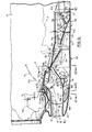
- Figure 5 is a side view, partly in section, of an engine having a particle separation air intake system according to the present invention;
- Figure 6 is a perspective view, from the front and top, showing the air intake system of Figure 5;
- Figure 7 is a side view showing the air intake system of Figure 6 in closed position against the engine nacelle;
- Figure 8 is a view similar to that of Figure 7 but showing the air intake system swung to an open position;
- Figure 9 is a sectional view along lines 9-9 of Figure 6;
- Figure 10 is a plan view taken in section along lines 10-10 of Figure 9;
- Figure 11 is a sectional view along lines 11-11 of Figure 9;
- Figure 12 is a sectional view along lines 12-12 of Figure 9;
- Figure 13 is a sectional view along lines 13-13 of Figure 9;
- Figure 14 is a perspective view, partly in section, of the front portion of the air intake system of Figure 6;
- Figure 15 is a perspective view of guide and divider plates of the intake system of Figure 6;
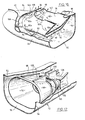
- Figure 16 is a partly broken away perspective view, taken from the rear and slightly above, of a portion of the intake system of Figure 6; and
- Figure 17 is a partly broken away perspective view, taken from above and from the front, of the rear portion of the intake system of Figure 6.
- Reference is first made to Figure 1, which shows a typical engine, nacelle and air intake system of the kind presently used in certain aircraft made by The de Havilland Aircraft of Canada, Limited. As shown, housed in the
nacelle 10 is agas turbine engine 12 which drives apropeller 14 through agearbox 16. Theengine 12 is mounted with itsair inlet 18 located at the rear of the engine and opening radially into alarge plenum 20. Air enters anintake duct 22, travels rearwardly, and then travels upwardly through ascreen 24 into theengine 12. Because the engine inlet faces rearwardly, foreign objects such as birds, sand and ice, which because of their momentum are unable to make the 180° turn into the engine air inlet, travel straight through and are bypassed out of theplenum 20 via atrapdoor 26. The system works well, but only a relatively few aircraft designs have a rearwardly facing engine which provides such particle separation. - Figure 2 shows a system used in many aircraft at the present time. The
engine 12 faces forwardly and air for the engine enters anintake duct 28 and travels directly into the engine. There is no arrangement for removing foreign objects which are ingested, and any such foreign objects may damage the engine. - Figure 3 shows a modification of the Figure 2 arrangement of a kind which has been currently proposed for removing foreign objects and particles. In the Figure 3 arrangement a
bypass duct 30 branches off themain intake duct 32 and removes about 15% of the intake air as bypass air. Ascreen 34 in themain duct 32 just downstream of thebypass duct 30 prevents foreign objects from travelling into the engine. Thescreen 34 is formed from heavy metal rods. - The Figure 3 arrangement has several serious disadvantages. Firstly, the
screen 34, even though made of heavy material, must be shock mounted in order to withstand the impact of heavy objects such as birds. Secondly, because thescreen 34 tends to ice, it must be electrically heated, thereby adding to the complexity and cost of the arrangement. Thirdly, each of the three ends of the intake duct arrangement must be shock mounted by means of a corrugated mounting, which adds weight and cost. Fourthly, when the engine is to be serviced, the nacelle must be removed and then the three branches of the intake duct must be separately removed, adding to the cost of servicing the engine. Finally, the loss of 15% of the intake air as bypass flow causes a reduction in the efficiency of the engine. - An attempt was made by The de Havilland Aircraft of Canada, Limited to avoid the disadvantages of the Figure 3 arrangement by adopting the Figure 4 arrangement. In the Figure 4 arrangement a
large plenum 36 is provided at the rear of theintake duct 38 and into which the intake duct discharges. It was intended that the air entering theintake duct 38 would find its way upwardly from theplenum 36 through an upwardly directedbranch duct 39 into theinlet 18 of the engine. Foreign objects and particles because of their momentum travel straight through into the rear of theplenum 36 for removal via thetrapdoor 26. - When the Figure 4 arrangement was tested, it was found that instabilities occurred and the entire arrangement began to vibrate. It is believed that the problem was that the air flowing upwardly into the
branch duct 39 directly from themain intake duct 38 interfered with air which first travelled into theplenum 36 and then attempted to travel upwardly into thebranch duct 39. In simplified terms it is believed that first one airstream would prevail and then the other, much like traffic in two streams at a set of traffic lights. The resultant vibration of the structure and turbulence in the air fed into the engine were extremely undesirable. - A
preferred intake structure 40 according to the invention is shown in Figures 5 to 17 and has been found to operate in a highly satisfactory manner. Thestructure 40 will first be described generally with reference to Figures 5 and 9. As there shown, theintake structure 40 includes amain intake duct 42. Aninlet airstream 44 entersduct 42 and is divided into aprimary airstream 46 and asecondary airstream 48. Theprimary airstream 46 turns sharply upwardly and then travels directly into theengine inlet 50 and through the engine intake duct indicated in dotted lines at 51. Thesecondary airstream 48 travels directly rearwardly into aplenum 52 located behindduct 42. Birds, stones, ice and the like entering themain intake duct 42 simply travel straight through theplenum 52 as shown byarrows 56, and exit through adoor 58 which is opened when required. - From the
plenum 52, a third airstream 60 (which may be equal to the entiresecondary airstream 48 if no other air is removed from the plenum 52) travels forwardly through anair duct 64 located below and to the sides of themain intake duct 42. When thethird airstream 60 reaches the front end of theair duct 64, it divides into twostreams air intake duct 42. Theairstreams stream 60c at the top of the mainair intake duct 42, and then travel rearwardly and upwardly through the peripheral gap formed by theengine inlet 50 and intake lip 86 (to be described), to rejoin theprimary airstream 46 flowing into theengine inlet 50 andengine intake duct 51. (A portion of the third airstream also travels from theplenum 52 directly forwardly and upwardly at the sides of theintake duct 42 to rejoin the primary air stream, as will be described.) - The structure shown (and to be described in more detail) has a number of important features and advantages, which include the following:
- 1. The arrangement shown produces no significant instabilities. Instead of the
third airstream 60 interfering with theprimary airstream 46 as both attempt to travel into the engine, thethird airstream 60 is guided forwardly and upwardly around the inlet duct and then fed into theprimary airstream 46 in a path which is generally substantially parallel to that of theprimary airstream 46, so that both join smoothly. The result is similar to a cloverleaf, rather than to the traffic light situation of Figure 4. - 2. At the point where the primary and secondary airstreams separate, a
cusp 68 is provided. Thecusp 68 creates a sort of air roller bearing, indicated at 70 in Figure 9. The rotatingair roller bearing 70 helps to separate thesecondary airstream 48 travelling rearwardly into theplenum 52 from thethird airstream 60 travelling forwardly into theduct 64. This improves the flow stability and reduces friction losses. - 3. Since the
door 58 need only be opened at times when foreign objects have been collected or are expected, there are normally no secondary air losses since no secondary air is vented without first passing through the engine. - 4. Since the entire air intake system can be mounted in a single housing which (as will be described) can be hinged downwardly away from the engine for access to the engine, servicing of the engine is greatly facilitated.
- 5. No blocking screens are required, thereby minimizing deicing and anti-icing problems.
- It is found that the invention solves a problem which in the past had been thought to be almost impossible to solve, i.e. it permits bypass of foreign objects without complexity and without creating significant instabilities, icing problems or substantial losses.
- A more detailed description of the preferred embodiment of the invention is as follows. As best shown in Figures 6 to 9 inclusive, the
intake structure 40 is formed as a unit in ahousing 72 connected at its rear to thenacelle 10 by hinges 73. Theintake structure 40 is normally held in closed position against thenacelle 10 by a set of latches 74 (Figure 6) which are conventional in nature and therefore will not be described in detail. As indicated, thelatches 74 can be released and theintake structure 40 swung downwardly as shown in Figure 8 for engine servicing. - The.
main intake duct 42 is centered laterally within thehousing 72. Theintake duct 42 is generally rectangular in cross-section, as shown in the drawings, but withrounded sides 76 and aninlet opening 77. Thebottom wall 78 of themain intake duct 42 terminates in the cusp or V-shapedformation 68, which consists of an upwardly curvedbottom wall portion 80 and a straightbottom wall portion 82. Both terminate atrear edges engine inlet 50, with aconcave filler plate 83 extending therebetween. At its sides the V-shaped formation orcusp 68 extends upwardly to the upper wall 98 (to be described) of the housing, as shown in Figures 9, 12 and 16. - The
top wall 84 of themain intake duct 42 slopes slightly upwardly rearwardly along the bulk of its length and then at its rear curves sharply upwardly at acurved portion 86, terminating just above the bottom of theengine inlet 50. Therear edge 88 of thecurved portion 86 also forms the front edge of a top opening 90 (Figures 6, 9 and 16) from themain intake duct 42 into theengine inlet 50. Thecurved portion 86 extends above the opening 90 and into theinlet 50 to help guide theprimary airstream 46 upwardly into theinlet 50. - The
housing 72 includes abottom wall 92, sidewalls 94, afront wall 96, and anupper wall 98. Afront opening 100 for themain intake duct 42 is located in thefront wall 84 of the housing. - The housing sidewalls 94 extend above the housing
upper wall 98 along the front part of thehousing 78 and terminate in a formed rim 102 (Figure 6). Therim 102 is shaped to fit the contour of the lower edge of thenacelle 10 and also to ensure that theentire housing 72 can be firmly secured to the nacelle. The shape of therim 102 is also arranged to facilitate access to the front of theengine 12. For this purpose thehousing sidewalls 94 each include an upwardly projectingportion 104 adjacent the front thereof, as best shown in Figures 6 to 8 and 14. The upwardly projectingsidewall portions 104 help to ensure that thehousing 72 will not detach from thenacelle 10 in use and also, when thehousing 72 is swung downwardly, expose the sides of the from ofengine 12 for servicing - The
lower portion 64a of theair duct 64 is defined in part by the space between thebottom wall 78 of themain intake duct 42 and thebottom wall 92 of thehousing 72. Theside portions 64b of theair duct 64 are formed by the spaces between thesidewalls 76 of themain intake duct 42 and thesidewalls 94 of thehousing 72. The front of theair duct 64 is defined by acurved plate 106, best shown in Figures 9 and 15, which extends from thehousing bottom wall 92 upwardly to a position above the front part of the main intakeduct top wall 84. Thecurved plate 106 has ahole 107 therein for theintake duct 42 to pass therethrough. Thetop portion 64c of theair duct 64 is defined by the space between the upper part of thecurved plate 106 and the curvedrear portion 86 of thetop wall 84 of themain intake duct 42. - A longitudinally extending
vertical divider plate 108 within thesecondary air duct 54 divides theair duct 64 laterally into two equal parts to improve the stability of thethird airstream 60 as it travels upwardly on each side of themain intake duct 42. - To reinforce the
housing 72, itsupper wall 98 extends from thefront wall 96 over thecurved plate 106, and is secured to thehousing front wall 96, thecurved plate 106, and thesidewalls 94. Theupper wall 98 then extends rearwardly to the rear of thehousing 72. - As shown in Figures 6 and 14, the
upper wall 98 includes a generally heart shaped opening 110 bordered by anupstanding rim 112. Theopening 110 is shaped to match the shape of astandard engine inlet 50. Theinlet 50 includes a downwardly and outwardly flared rim 114 (Figure 9) fitted with a conventional outwardly facing O-ring 116 against which therim 112 seals when thehousing 72 is swung to its closed position. - The
plenum 52, in the rear portion ofhousing 72, is defined by two generally funnel-shapedstructures door 58. The funnel-shapedstructures space 122 which allows a fourth stream of air 124 (but not particles) travelling rearwardly through the funnel-shaped structures to travel upwardly and then rearwardly through the open rear end of thehousing 72 and into an engine oil cooler 126 located behind thehousing 72. This allows theintake structure 40 to perform dual duty, in that it provides particle free air both for the engine and also for the oil cooler of the engine. - The funnel-shaped
structures flanges structures upper wall 98 of thehousing 72. - The
door 58 includes a sector-shapedfront surface 132, a flatlower surface 134 which is flush with thehousing bottom wall 92 when the door is closed, and anupper surface 136 connected to ahydraulic actuator 138. When thedoor 58 is to be opened, theactuator 138 moves it to the dotted line position in Figure 9, permitting particles and other objects to exit from the intake structure. - The operation of the system is as follows. As shown in Figure 9, there is a stagnation point S just downstream of the
engine inlet 50. Air which is directed toward theengine inlet 50 forwardly of the stagnation point S travels into the engine inlet asprimary airstream 46. This is typically about 85% of the air enteringmain intake duct 42. Air directed toward the stagnation point S is indicated byarrow 140. Air flowing rearwardly ofarrow 140 travels into theplenum 52 as thesecondary airstream 48, together with the particles to be separated. Dimension d1 betweenarrow 140 and thelower wall 78 of the main intake duct is proportioned so that about 15% of the intake air is bled off as secondary air. - It will be noted that most dense particles entering the
intake duct 42 will travel directly rearwardly into theplenum 52. The arrangement by which thethird airstream 60c is fed into theengine inlet 50 forwardly of thewall 86 allows thecurved wall 86 to be moved further rearwardly than would otherwise be possible, and this reduces the number of "line of sight" paths which a particle can follow to enter the engine inlet. Moreover the rearward movement of thecurved wall 86 has been accomplished without incurring a substantial total pressure loss in the air fed to the engine. Although there is a "line of sight" between theinlet opening 77 and theengine inlet 50, the line is quite oblique, which reduces the likelihood of particles entering theengine inlet 50. - From the
plenum 52, thethird airstream 60 travels forwardly through the air duct 64 (includingportions main intake duct 42. Thethird airstream 60 is equal in flow to thesecondary airstream 48 less the sum of any air flows travelling to thetrapdoor 58, or to theoil cooler 126, or lost in leaks. The main portion of thethird airstream 60 flows fromlower duct 64 upwardly on each side of themain intake duct 42, and then rearwardly and upwardly throughduct portion 64c, overcurved portion 86 and into theengine inlet 50. As will be apparent from Figure 16, apart 60d of thethird airstream 60 may also tend to travel around the sides of thecusp 68, directly forwardly and upwardly over the sides of themain intake duct 42, and then over the side edges of the upper opening 90 in themain intake duct 42. To accommodate this flow, which also merges smoothly with the primary airstream, the upper side edges of opening 90 are cut back or notched as indicated at 142, from a location forwardly of the stagnation point S forwardly to blend in with thelip 88 forming a continuous flow gap betweenduct 42 andengine inlet 50. Rearwardly ofnotches 142 the upper side edges ofduct 42 seal against thetop surface 98 of the structure, as shown in Figure 9. This prevents secondary air from feeding forwardly into theengine inlet 50 aft of the stagnation point S and causing flow separation. - The location of
lip 88, which defines the dimension of the flow gap between theduct 42 and theengine inlet 50, is important. This lip, which guides theprimary airstream 46, should be located so as to provide efficient turning of theprimary airstream 46 into the engine inlet. 50. Thus thelip 88 should not be too far fromwall 51a. However, the spacing must be sufficient so as not to choke off thethird airstream 60c. However, the spacing betweenlip 88 andwall 51 a should be sufficiently small as not to create a larger third airstream than necessary, since it is desired to have most of the intake air travel directly into theengine inlet 50 which is the most efficient path. - It will also be noted that in the arrangement shown, the
plenum 52 is pressurized, helping to produce a positive pressure on the convex side of theprimary airstream 46 flowing through themain intake duct 42 into theengine inlet 50. This helps to deflect theprimary airstream 46 into the engine inlet, although of course the main deflecting force consists of the suction produced by the engine. As mentioned, the main separation of the primary and secondary airstreams occurs at the stagnation point S which will vary in position with variation of the third airstream to primary airstream flow ratio. - The
cusp 68, which produces anair roller bearing 70, separates the secondary and third airstreams from each other, and thus reduces losses in the system. Without such flow separation, buffeting between the forward and rearward flows tends to occur, and this creates not only losses but also undesired vibrations. - A further advantage of the system shown is that a simple boot de-icing system may be used, consisting simply of an expansible rubber boot (not shown) fitted around the
opening 100 of the mainair intake duct 42. Although ice will be - broken from the boot and will be shed into the
main air intake 42 during operation, the ice will travel rearwardly into theplenum 52 where it can be disposed of without entering the engine. A complex anti-icing system (consisting of heating structure to prevent the formation of ice on engine intake screens) is not normally required. - Although a specific arrangement of air passages has been shown, it will be appreciated that various changes may be made while still preserving the feature of turning the primary airstream sharply upwardly while permitting a secondary airstream containing objects therein to travel into a plenum, and then guiding a third airstream from the plenum forwardly, separated from the second airstream, to rejoin the main airstream in an efficient manner.
- In addition, while the system has been shown located below an aircraft engine located in a nacelle, the separator of the invention can be differently oriented with respect to the engine, and can be used with engines in applications other than in aircraft but where dust or particles may present a problem.
Claims (16)
Applications Claiming Priority (2)
| Application Number | Priority Date | Filing Date | Title |
|---|---|---|---|
| CA000409600A CA1201894A (en) | 1982-08-17 | 1982-08-17 | Air intake system for engine |
| CA409600 | 1982-08-17 |
Publications (3)
| Publication Number | Publication Date |
|---|---|
| EP0103384A2 EP0103384A2 (en) | 1984-03-21 |
| EP0103384A3 EP0103384A3 (en) | 1984-07-11 |
| EP0103384B1 true EP0103384B1 (en) | 1988-09-28 |
Family
ID=4123425
Family Applications (1)
| Application Number | Title | Priority Date | Filing Date |
|---|---|---|---|
| EP83304390A Expired EP0103384B1 (en) | 1982-08-17 | 1983-07-29 | Air intake system for engine |
Country Status (3)
| Country | Link |
|---|---|
| EP (1) | EP0103384B1 (en) |
| CA (1) | CA1201894A (en) |
| DE (1) | DE3378137D1 (en) |
Cited By (1)
| Publication number | Priority date | Publication date | Assignee | Title |
|---|---|---|---|---|
| US9500129B2 (en) | 2012-10-29 | 2016-11-22 | Honeywell International Inc. | Turboshaft engines having improved inlet particle scavenge systems and methods for the manufacture thereof |
Families Citing this family (14)
| Publication number | Priority date | Publication date | Assignee | Title |
|---|---|---|---|---|
| US4685942A (en) * | 1982-12-27 | 1987-08-11 | General Electric Company | Axial flow inlet particle separator |
| GB2203801B (en) * | 1987-04-14 | 1991-11-27 | Rolls Royce Plc | A gas turbine engine |
| US4938021A (en) * | 1988-10-27 | 1990-07-03 | Sundstrand Corporation | Sustainer propulsion system |
| US5123240A (en) * | 1990-03-19 | 1992-06-23 | General Electric Co. | Method and apparatus for ejecting foreign matter from the primary flow path of a gas turbine engine |
| GB2259328B (en) * | 1991-09-03 | 1995-07-19 | Gen Electric | Gas turbine engine variable bleed pivotal flow splitter |
| GB9906621D0 (en) * | 1999-03-23 | 1999-05-19 | British Aerospace | Vehicle propulsion systems |
| RU2174616C2 (en) * | 1999-09-21 | 2001-10-10 | Государственное унитарное предприятие "Завод им. В.Я. Климова" - дочернее предприятие государственного унитарного предприятия Военно-промышленный комплекс "МАПО" | Intake unit for turboprop engine |
| RU2189474C1 (en) * | 2000-12-27 | 2002-09-20 | Общество с ограниченной ответственностью "Проектно-конструкторское бюро "Энергия" | Method of supply and discharge of cleaned cooling air from turbogenerator |
| JP4592703B2 (en) * | 2004-09-15 | 2010-12-08 | 株式会社エヌ・ティ・ティ・ドコモ | Mobile communication system, radio control station, radio base station, mobile station, and mobile communication method |
| EP1674694B1 (en) * | 2004-12-23 | 2014-02-12 | Rolls-Royce plc | Compressor intake duct |
| ATE497324T1 (en) * | 2008-11-28 | 2011-02-15 | Alcatel Lucent | EQUIPMENT PROTECTION METHOD AND DEVICE |
| US20120070271A1 (en) | 2010-09-21 | 2012-03-22 | Urban Justin R | Gas turbine engine with bleed duct for minimum reduction of bleed flow and minimum rejection of hail during hail ingestion events |
| FR3039209B1 (en) * | 2015-07-23 | 2017-07-14 | Snecma | AIR INLET HANDLE FOR AN AIRCRAFT TURBOPROPOWER |
| FR3075761A1 (en) * | 2017-12-21 | 2019-06-28 | Airbus Operations | ANTERIOR PLATFORM PART OF A NACELLE COMPRISING AN INCLINE RIGIDIFICATION FRAME |
Family Cites Families (3)
| Publication number | Priority date | Publication date | Assignee | Title |
|---|---|---|---|---|
| US3329377A (en) * | 1965-10-11 | 1967-07-04 | United Aircraft Canada | Protection for aircraft engines against snow, ice and airborne particles |
| US3371471A (en) * | 1965-10-15 | 1968-03-05 | Avco Corp | Sand and dust collector for engine air inlets |
| US3952972A (en) * | 1974-12-24 | 1976-04-27 | United Aircraft Of Canada Limited | Inertial separator |
-
1982
- 1982-08-17 CA CA000409600A patent/CA1201894A/en not_active Expired
-
1983
- 1983-07-29 EP EP83304390A patent/EP0103384B1/en not_active Expired
- 1983-07-29 DE DE8383304390T patent/DE3378137D1/en not_active Expired
Non-Patent Citations (1)
| Title |
|---|
| PRODUCT ENGINEERING, vol. 45, no. 6, June 1974, Cleveland, GB, "Turboprop aircraft is reliable, easy to maintain", pp. 12,13 * |
Cited By (1)
| Publication number | Priority date | Publication date | Assignee | Title |
|---|---|---|---|---|
| US9500129B2 (en) | 2012-10-29 | 2016-11-22 | Honeywell International Inc. | Turboshaft engines having improved inlet particle scavenge systems and methods for the manufacture thereof |
Also Published As
| Publication number | Publication date |
|---|---|
| EP0103384A2 (en) | 1984-03-21 |
| EP0103384A3 (en) | 1984-07-11 |
| CA1201894A (en) | 1986-03-18 |
| DE3378137D1 (en) | 1988-11-03 |
Similar Documents
| Publication | Publication Date | Title |
|---|---|---|
| US4456458A (en) | Air intake system for engine | |
| EP0103384B1 (en) | Air intake system for engine | |
| US4346860A (en) | Vane fairing for inertial separator | |
| US4617028A (en) | Aircraft engine air intake including a foreign object separator | |
| EP1942258B1 (en) | Particle separator using boundary layer control | |
| US7611093B2 (en) | Dual flow APU inlet and associated systems and methods | |
| US5123240A (en) | Method and apparatus for ejecting foreign matter from the primary flow path of a gas turbine engine | |
| US3998048A (en) | Ram air intakes of rotary-wing aircraft turbine engines | |
| US3766719A (en) | Particle and moisture separator for engine inlet | |
| US4836473A (en) | Apparatus for influencing a boundary layer on the surface of a body moving through a medium | |
| US3329377A (en) | Protection for aircraft engines against snow, ice and airborne particles | |
| US4291530A (en) | Gas turbine engine cowling | |
| EP2969764B1 (en) | Interchangeable inlet protection systems for air intakes of aircraft engines and related methods | |
| US4004760A (en) | Device for preventing foreign matters from being sucked into a gas turbine engine for an aircraft | |
| US20090261208A1 (en) | Aircraft engine inlet pivotable barrier filter | |
| GB2205903A (en) | Variable geometry jet engine nacelle | |
| US4502875A (en) | Air intakes of aircraft mounted gas turbine engines | |
| EP0940338B1 (en) | Gearbox breather outlet | |
| US4425756A (en) | Gas turbine engine and its associated air intake system | |
| US4844382A (en) | Dual turning vane air inlet assembly | |
| US8801823B2 (en) | Device, method, and system to separate liquid and particulate matter from the airstream of a centrifugal fan | |
| US10266275B1 (en) | Pressure recovery device for an aircraft engine air intake | |
| US2405102A (en) | Air intake filter for aircraft engines | |
| JPS63117127A (en) | Separator for foreign matter | |
| US20110088652A1 (en) | Ram induction system |
Legal Events
| Date | Code | Title | Description |
|---|---|---|---|
| PUAI | Public reference made under article 153(3) epc to a published international application that has entered the european phase |
Free format text: ORIGINAL CODE: 0009012 |
|
| AK | Designated contracting states |
Designated state(s): DE FR GB IT |
|
| PUAL | Search report despatched |
Free format text: ORIGINAL CODE: 0009013 |
|
| AK | Designated contracting states |
Designated state(s): DE FR GB IT |
|
| 17P | Request for examination filed |
Effective date: 19841222 |
|
| GRAA | (expected) grant |
Free format text: ORIGINAL CODE: 0009210 |
|
| AK | Designated contracting states |
Kind code of ref document: B1 Designated state(s): DE FR GB IT |
|
| REF | Corresponds to: |
Ref document number: 3378137 Country of ref document: DE Date of ref document: 19881103 |
|
| ITF | It: translation for a ep patent filed | ||
| ET | Fr: translation filed | ||
| PLBE | No opposition filed within time limit |
Free format text: ORIGINAL CODE: 0009261 |
|
| STAA | Information on the status of an ep patent application or granted ep patent |
Free format text: STATUS: NO OPPOSITION FILED WITHIN TIME LIMIT |
|
| 26N | No opposition filed | ||
| ITTA | It: last paid annual fee | ||
| ITPR | It: changes in ownership of a european patent |
Owner name: CAMBIO RAGIONE SOCIALE;DE HAVILLAND CANADA LTD |
|
| REG | Reference to a national code |
Ref country code: FR Ref legal event code: CD |
|
| REG | Reference to a national code |
Ref country code: FR Ref legal event code: TP |
|
| ITPR | It: changes in ownership of a european patent |
Owner name: CESSIONE;BOEING OF CANADA LTD "DOWNSVIEW" |
|
| ITPR | It: changes in ownership of a european patent |
Owner name: CESSIONE;DE HAVILLAND INC. |
|
| REG | Reference to a national code |
Ref country code: FR Ref legal event code: TP |
|
| REG | Reference to a national code |
Ref country code: FR Ref legal event code: TP |
|
| REG | Reference to a national code |
Ref country code: GB Ref legal event code: 732E |
|
| REG | Reference to a national code |
Ref country code: GB Ref legal event code: IF02 |
|
| PGFP | Annual fee paid to national office [announced via postgrant information from national office to epo] |
Ref country code: GB Payment date: 20020725 Year of fee payment: 20 |
|
| PGFP | Annual fee paid to national office [announced via postgrant information from national office to epo] |
Ref country code: FR Payment date: 20020821 Year of fee payment: 20 |
|
| PGFP | Annual fee paid to national office [announced via postgrant information from national office to epo] |
Ref country code: DE Payment date: 20020824 Year of fee payment: 20 |
|
| PG25 | Lapsed in a contracting state [announced via postgrant information from national office to epo] |
Ref country code: GB Free format text: LAPSE BECAUSE OF EXPIRATION OF PROTECTION Effective date: 20030728 |
|
| REG | Reference to a national code |
Ref country code: GB Ref legal event code: PE20 |