EP0103339A1 - Television picture scrambling method, and descrambling apparatus therefor - Google Patents
Television picture scrambling method, and descrambling apparatus therefor Download PDFInfo
- Publication number
- EP0103339A1 EP0103339A1 EP83201293A EP83201293A EP0103339A1 EP 0103339 A1 EP0103339 A1 EP 0103339A1 EP 83201293 A EP83201293 A EP 83201293A EP 83201293 A EP83201293 A EP 83201293A EP 0103339 A1 EP0103339 A1 EP 0103339A1
- Authority
- EP
- European Patent Office
- Prior art keywords
- switch
- luminance
- components
- chrominance
- line
- Prior art date
- Legal status (The legal status is an assumption and is not a legal conclusion. Google has not performed a legal analysis and makes no representation as to the accuracy of the status listed.)
- Ceased
Links
- 238000000034 method Methods 0.000 title claims abstract description 15
- 238000012545 processing Methods 0.000 claims abstract description 13
- 230000005540 biological transmission Effects 0.000 claims abstract description 10
- 238000005194 fractionation Methods 0.000 claims abstract description 6
- 230000003111 delayed effect Effects 0.000 claims abstract description 4
- 230000015654 memory Effects 0.000 claims description 19
- 230000008859 change Effects 0.000 claims description 4
- 230000001360 synchronised effect Effects 0.000 claims description 3
- 230000006870 function Effects 0.000 claims description 2
- 235000021183 entrée Nutrition 0.000 description 6
- 230000008569 process Effects 0.000 description 3
- 240000008042 Zea mays Species 0.000 description 1
- 230000007547 defect Effects 0.000 description 1
- 238000012217 deletion Methods 0.000 description 1
- 230000037430 deletion Effects 0.000 description 1
- 230000008034 disappearance Effects 0.000 description 1
- 210000000540 fraction c Anatomy 0.000 description 1
- 230000004048 modification Effects 0.000 description 1
- 238000012986 modification Methods 0.000 description 1
- 238000012552 review Methods 0.000 description 1
- 238000001228 spectrum Methods 0.000 description 1
- 238000011282 treatment Methods 0.000 description 1
Images
Classifications
-
- H—ELECTRICITY
- H04—ELECTRIC COMMUNICATION TECHNIQUE
- H04N—PICTORIAL COMMUNICATION, e.g. TELEVISION
- H04N7/00—Television systems
- H04N7/16—Analogue secrecy systems; Analogue subscription systems
- H04N7/167—Systems rendering the television signal unintelligible and subsequently intelligible
- H04N7/169—Systems operating in the time domain of the television signal
- H04N7/1696—Systems operating in the time domain of the television signal by changing or reversing the order of active picture signal portions
Definitions
- the present invention relates to a method of scrambling television images in which it is intended, for the video signals of the scanning lines, to operate in the periods situated between the line blanking periods a splitting whose position is defined so pseudo-random and a change in the order of the fractions thus formed. It also relates to a device for deciphering scrambled television images according to this method.
- the object of the invention is to provide a scrambling process which is difficult to decrypt for time multiplex transmission systems of analog components (known as MAC from the equivalent English expression "Multiplexed Analogue Components”) proposed in particular in the report 116 / 81 - UDC 621.396.946 "Direct television broadcasts by satellite: desirability of a new transmission standard" by K. Lucas and MD Windram, Independent Broadcasting Authority (IBA), Crawley Court, Winchester, Hants, S021 - 2QA, or also, more recently, in the article “Television systems for DBS” published in the review "The Radio and Electronic Engineer", Vol. 52, n ° 7, July 1982, p.311 et seq.
- This M.A.C. ensures the successive transmission, for each scan line, of the chrominance and luminance components, separated by a short reference period (called clamping) at the black level: an example of an M.A.C. signal is shown in Figure 5 of the cited report.
- the invention relates for this purpose to a method such as defined above and characterized in that for so-called MAC systems for transmitting tvoe video signals with time multiplexing of the analog chrominance and luminance components separated by a reference period, said components are at transmission, in the periods between line deletion periods. one then the other, each divided into two consecutive signals, the first of which is then delayed by the duration of the second and the second advanced by the duration of the first, the reference periods which separate these components being exempt from this fractionation processing and change of order and said processing being intended to be applied in the opposite direction to reception.
- the interference method thus proposed is very effective, in that it has the advantages inherent in the method described in the cited patent application while also providing for excluding from interference the reference periods located between the chrominance components and of luminance, periods which, if they had been included for each line in the period subject to interference, would have been fairly easily identifiable in the encrypted signals.
- the method of transmitting MAC signals provides. for each scanning line, as shown for example in FIG. 5 already cited from the IBA report, the successive transmission of a line synchronization word, of a reference period at zero chrominance level, of the chrominance signal, of a period of reference to the black level, and to the luminance signal.
- the advantages of such a signal structure appear on page 8, column 2, of the report, and will not be repeated here, the main of them however being the successive nature of the transmission which causes the disappearance of the entanglement of the chrominance and luminance spectra; this overlap required in fact well known treatments but relatively complex s for image reconstruction at the reception.
- the scrambling method according to the invention consists, on transmission, in dividing on each scan line the two chrominance and luminance components, independently of one another, each into two consecutive signals, the first of which is then delayed by the duration of the second and the second advanced by the duration of the first.
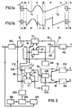
- Figure 1a shows the MAC video signal, not scrambled, for a scan line
- Figure 1b the same but scrambled signal: compared to the signal not scrambled composed of synchronization word A, reference periods B and E, of the chrominance signal CD and of the luminance signal FG (these last two signals being represented with any shapes, very distinct for understanding the processing carried out), the scrambled signal is therefore transmitted according to the ABDCEGF sequence, which does not affect the reference period E.
- the reception processing then consists in ensuring the restoration of the original sequences, for the clear reconstitution of the chrominance and luminance components of the line sweep considered.
- the operation of the decryption device thus composed is as follows.
- the pseudo-random sequence generator 400 which is synchronized by the counter 330 and which receives from the access control circuit 410 the key deciphered by the latter upon reception of the scrambled MAC signals, generates a random digital word from which the two are deduced.
- the period B is written at the start of the memory, then the fraction D, starting at the address of the abscissa x 1 , and the fraction C between B and D; this writing is carried out successively in the memory C 1 or the memory C 2 according to the parity of the line, using the writing counter 300 controlled by the generator of pseudo-random sequences 400 and addressing one or the other of the two memories depending on the position of a switch 80.
- the writing of the chrominance component being completed the same is written successively in the memory Y 1 or the memory Y 2 according to the parity of the line and using the same writing counter 300 which addresses one either of these two memories as a function of the position of a switch 30, the reference period E at the start of memory, then the fraction G starting at the address of the abscissa x 2 , and the fraction F between E and G.
- the memories Y 1 and C 1 , or Y 2 and C 2 are read simultaneously in increasing order of addresses, using the counters 310 and 320.
- the reading frequencies of the luminance and chrominance memories are chosen so that the useful signals FG and CD are restored in a time corresponding to the useful scanning time of the line, that is to say approximately 52 microseconds in the current European standard 625 lines.
- the chrominance reading frequency is therefore lower than the luminance reading frequency which itself is lower than the writing frequency of the counter 300.
- the reading counter 320 addresses the memories C 1 and C 2 alternately via a switch 90, and the counter 310 the memories Y1 and Y 2 alternately by means of a switch 40.
- the presence of the digital delay line 230 is not linked to the decryption itself; this delay line is provided to allow the simultaneous restitution, at the output of the digital-analog converters 240 and 250, of the color difference signals U and V which are transmitted alternately.
- the control of this delay line 230 is ensured by the read counter 320 of the memories C 1 and C 2 '
Abstract
Procédé de brouillage d'images de télévision pour lesquelles les signaux vidéo de chaque ligne de balayage sont du type dit M.A.C., c'est-à-dire à multiplexage temporel des composantes analogiques de chrominance et de luminance, caractérisé en ce qu'à l'émission lesdites composantes sont, sur chaque ligne, l'une puis l'autre, chacune fractionnées en deux signaux consécutifs C et D d'une part et F et G d'autre part, dont le premier C ou F est alors retardé de la durée du second et le second D ou G avancé de la durée du premier, les périodes de référence B et E qui précèdent respectivement ces composantes étant exemptées de ce traitement, les positions des points de fractionnement étant déduites de séquences numériques pseudoaléatoires, et ledit traitement étant destiné à être appliqué en sens inverse à la réception pour la restitution simultanée des signaux de luminance Y et de différence de couleur U et V.Method for scrambling television images for which the video signals of each scanning line are of the so-called MAC type, that is to say with time multiplexing of the analog chrominance and luminance components, characterized in that at transmission said components are, on each line, one then the other, each divided into two consecutive signals C and D on the one hand and F and G on the other hand, the first C or F of which is then delayed by the duration of the second and the second D or G advanced by the duration of the first, the reference periods B and E which respectively precede these components being exempt from this processing, the positions of the fractionation points being deduced from pseudo-random digital sequences, and said processing being intended to be applied in opposite direction to the reception for the simultaneous restitution of the signals of luminance Y and of color difference U and V.
Description
La présente invention concerne un procédé de brouillage d'images de télévision dans lequel il est prévu, pour les signaux vidéo des lignes de balayage, d'opérer dans les périodes situées entre les périodes de suppression ligne un fractionnement dont la position est définie de façon pseudoaléatoire et un changement de l'ordre des fractions ainsi constituées. Elle concerne également un dispositif de déchiffrement d'images de télévision brouillées selon ce procédé.The present invention relates to a method of scrambling television images in which it is intended, for the video signals of the scanning lines, to operate in the periods situated between the line blanking periods a splitting whose position is defined so pseudo-random and a change in the order of the fractions thus formed. It also relates to a device for deciphering scrambled television images according to this method.
La demande de brevet français n° 78 21 888 déposée le 20 juillet 1978 au nom de l'Etablissement Public de Diffusion dit "Télédiffusion de France" et publiée le 15 février 1980 sous le n° 2 431 809 décrit un procédé de brouillage d'images de télévision tel que défini ci-dessus.French patent application No. 78 21 888 filed on July 20, 1978 in the name of the Public Broadcasting Establishment known as "Télédiffusion de France" and published on February 15, 1980 under No. 2,431,809 describes a jamming process for television images as defined above.
Le but de l'invention est de procurer un procédé de brouillage difficile à décrypter pour les sytèmes de transmission de multiplexage temporel de composantes analogiques (dit M.A.C. d'après l'expression anglaise équivalente "Multiplexed Analogue Components") proposés notamment dans le rapport 116/81 - UDC 621.396.946 "Direct télévision broadcasts by satellite : desirability of a new transmission standard" par K. Lucas et M.D Windram, Indépendant Broadcasting Authority (IBA), Crawley Court, Winchester, Hants, S021 - 2QA, ou également, plus récemment, dans l'article "Television systems for D B S" paru dans la revue "The Radio and Electronic Engineer", Vol. 52, n° 7, juillet 1982, p.311 et suivantes. Ce système M.A.C. assure la transmission successive, pour chaque ligne de balayage, des composantes de chrominance et de luminance, séparées par une courte période de référence (dite de clamping) au niveau de noir : un exemple de signal M.A.C. est représenté sur la figure 5 du rapport cité.The object of the invention is to provide a scrambling process which is difficult to decrypt for time multiplex transmission systems of analog components (known as MAC from the equivalent English expression "Multiplexed Analogue Components") proposed in particular in the report 116 / 81 - UDC 621.396.946 "Direct television broadcasts by satellite: desirability of a new transmission standard" by K. Lucas and MD Windram, Independent Broadcasting Authority (IBA), Crawley Court, Winchester, Hants, S021 - 2QA, or also, more recently, in the article "Television systems for DBS" published in the review "The Radio and Electronic Engineer", Vol. 52, n ° 7, July 1982, p.311 et seq. This M.A.C. ensures the successive transmission, for each scan line, of the chrominance and luminance components, separated by a short reference period (called clamping) at the black level: an example of an M.A.C. signal is shown in Figure 5 of the cited report.
L'invention concerne à cet effet un procédé tel que défini précédemment et caractérisé en ce que pour les systèmes dits M.A.C. de transmission de signaux vidéo du tvoe à multiplexage temporel des composantes analogiques de chrominance et de luminance séparées par une période de référence, lesdites composantes sont à l'émission, dans les périodes situées entre les périodes de suppression ligne. l'une puis l'autre fractionnées chacune en deux signaux consécutifs dont le premier est alors retardé de la durée du second et le second avancé de la durée du premier, les périodes de référence qui séparent ces composantes étant exemptées de ce traitement de fractionnement et de changement d'ordre et ledit traitement étant destiné à être appliqué en sens inverse à la réception.The invention relates for this purpose to a method such as defined above and characterized in that for so-called MAC systems for transmitting tvoe video signals with time multiplexing of the analog chrominance and luminance components separated by a reference period, said components are at transmission, in the periods between line deletion periods. one then the other, each divided into two consecutive signals, the first of which is then delayed by the duration of the second and the second advanced by the duration of the first, the reference periods which separate these components being exempt from this fractionation processing and change of order and said processing being intended to be applied in the opposite direction to reception.
Le procédé de brouillage ainsi proposé est très efficace, en ce sens qu'il possède les avantages inhérents au procédé décrit dans la demande de brevet citée tout en prévoyant en outre d'exclure du brouillage les périodes de référence situées entre les composantes de chrominance et de luminance, périodes qui, si elles avaient été incluses pour chaque ligne dans la période soumise au brouillage, auraient été assez facilement repérables dans les signaux chiffrés.The interference method thus proposed is very effective, in that it has the advantages inherent in the method described in the cited patent application while also providing for excluding from interference the reference periods located between the chrominance components and of luminance, periods which, if they had been included for each line in the period subject to interference, would have been fairly easily identifiable in the encrypted signals.
Les particularités de cette invention, ainsi définies, vont apparaître de façon plus précise dans la description qui suit et dans les dessins annexés, donnés à titre d'exemple et dans lesquels :
- - les figures 1a et 1b représentent respectivement. pour une ligne de balayage, un exemple de signal vidéo de tvoe M.A.C.. non brouillé, et ce même signal mais brouillé conformément au procédé selon l'invention ;
- - la figure 2 montre un exemple de réalisation d'un dispositif de déchiffrage de signaux vidéo ainsi brouillés.
- - Figures 1a and 1b show respectively. for a scan line, an example of tvoe MAC video signal. not scrambled, and this same signal but scrambled according to the method according to the invention;
- - Figure 2 shows an embodiment of a device for deciphering video signals thus scrambled.
Le procédé de transmission de signaux M.A.C. prévoit. pour chaque ligne de balayage, comme le montre par exemple la figure 5 déjà citée du rapport IBA, la transmission successive d'un mot de sychronisation ligne, d'une période de référence au niveau zéro de chrominance, du signal de chrominance, d'une période de référence au niveau du noir, et du signal de luminance. Les avantages d'une telle structure de signal apparaissent en page 8, colonne 2, du rapport, et ne seront pas repris ici, le principal d'entre eux étant cependant le caractère successif de la transmission qui entraîne la disparition de l'enchevêtrement des spectres de chrominance et de luminance ; cette imbrication nécessitait en effet des traitements bien connus mais relativement complexes pour lasreconstitution de l'image à la réception.The method of transmitting MAC signals provides. for each scanning line, as shown for example in FIG. 5 already cited from the IBA report, the successive transmission of a line synchronization word, of a reference period at zero chrominance level, of the chrominance signal, of a period of reference to the black level, and to the luminance signal. The advantages of such a signal structure appear on page 8, column 2, of the report, and will not be repeated here, the main of them however being the successive nature of the transmission which causes the disappearance of the entanglement of the chrominance and luminance spectra; this overlap required in fact well known treatments but relatively complex s for image reconstruction at the reception.
Le procédé de brouillage selon l'invention consiste, à l'émission, à fractionner sur chaque ligne de balayage les deux composantes de chrominance et de luminance, indépendamment l'une de l'autre, chacune en deux signaux consécutifs dont le premier est alors retardé de la durée du second et le second avancé de la durée du premier. Ce procédé est mis en évidence sur la figure 1, où la figure 1a montre le signal vidéo de type M.A.C., non brouillé, pour une ligne de balayage, et la figure 1b ce même signal mais brouillé : par rapport au signal non brouillé composé du mot de synchronisation A, des périodes de référence B et E, du signal de chrominance CD et du signal de luminance FG (ces deux derniers signaux étant représentés avec des formes quelconques, bien distinctes pour la compréhension du traitement effectué), le signal brouillé est donc transmis selon la séquence ABDCEGF, qui n'affecte pas la période de référence E. Le traitement à la réception consiste alors à assurer le rétablissement des séquences d'origine, pour la reconstitution en clair des composantes de chrominance et de luminance de la ligne de balayage considérée.The scrambling method according to the invention consists, on transmission, in dividing on each scan line the two chrominance and luminance components, independently of one another, each into two consecutive signals, the first of which is then delayed by the duration of the second and the second advanced by the duration of the first. This process is highlighted in Figure 1, where Figure 1a shows the MAC video signal, not scrambled, for a scan line, and Figure 1b the same but scrambled signal: compared to the signal not scrambled composed of synchronization word A, reference periods B and E, of the chrominance signal CD and of the luminance signal FG (these last two signals being represented with any shapes, very distinct for understanding the processing carried out), the scrambled signal is therefore transmitted according to the ABDCEGF sequence, which does not affect the reference period E. The reception processing then consists in ensuring the restoration of the original sequences, for the clear reconstitution of the chrominance and luminance components of the line sweep considered.
Cette reconstitution est possible par exemple à l'aide du dispositif de déchiffrage représenté sur la figure 2 et qui comprend les éléments essentiels d'un décodeur classique numérique de signaux vidéo de type M.A.C. auxquels sont associés, selon l'invention, une modification du compteur d'adressage écriture des mémoires, un générateur de séquences numériques pseudoaléatoires et, pour la commande de ce dernier, un circuit de contrôle d'accès. Plus précisément, ce dispositif de déchiffrage est composé des éléments suivants :
- (1) des circuits d'entrée :
- (a) un convertisseur analogique-numérique 100 qui reçoit les signaux M.A.C. brouillés ;
- (b) un
commutateur 10 à trois sorties ;
- (2) des circuits de traitement de la composante de luminance
- (c) un ensemble de trois voies en
parallèle commutateur 10 aux trois entrées d'un commutateur 20, les première etdeuxième voies 110 et 120 comprenant respectivement une première et une deuxième mémoire Y1 et Y2 de stockage de la composante de luminance, adressées alternativement par un compteur d'écriture 300 et un premier compteur de lecture 310, alors que latroisième voie 130 est une voie directe ; - (d) un premier convertisseur numérique-analogique 140 qui reçoit la sortie du
commutateur 20 et délivre le signal de luminance couramment appelé Y ;
- (c) un ensemble de trois voies en
- (3) des circuits de traitement de la composante de chrominance :
- (e) un ensemble de deux voies en
parallèle 210 et 220 qui, par l'intermédiaire d'une troisième et d'une quatrième mémoire C1 et C2 de stockage de la composante de chrominance adressées alternativement par le compteur d'écriture 300 et un deuxième compteur delecture 320, sont reliées respectivement aux deux entrées d'un commutateur 50, la sortie de ce commutateur étant reliée d'une part à l'entrée d'une ligne à retard numérique 230 commandée par le compteur de lecture 320 (et réalisée par exemple sous forme d'un registre à décalage) pour retarder de la durée d'une ligne la composante de chrominance, et d'autre part à la première entrée respectivement d'un commutateur 60 et d'un commutateur 70 dont l'autre entrée reçoit la sortie de ladite ligne à retard ; - (f) des deuxième et troisième convertisseurs nunéri- ques-analogiques 240 et 250 qui reçoivent la sortie des
commutateurs 60 et 70 respectivement et délivrent les signaux de différence de couleur couramment appelés U et V ;
- (g) un
compteur 330 des lignes à l'intérieur de chaque trame ; - (h) un générateur de séquences numériques pseudoaléatoires 400 synchronisé par l'intermédiaire du compteur de
lignes 330 ;
- (i) un circuit de contrôle d'accès 410 qui fournit au générateur de séquences pseudoaléatoires un mot de départ constituant la clé de chiffrage.
- (e) un ensemble de deux voies en
- (1) input circuits:
- (a) an analog-to-
digital converter 100 which receives the scrambled MAC signals; - (b) a
switch 10 with three outputs;
- (a) an analog-to-
- (2) circuits for processing the luminance component
- (c) a set of three
parallel channels switch 10 to the three inputs of aswitch 20, the first andsecond channels write counter 300 and a first read counter 310, while thethird channel 130 is a direct channel; - (d) a first digital-
analog converter 140 which receives the output of theswitch 20 and delivers the luminance signal commonly called Y;
- (c) a set of three
- (3) circuits for processing the chrominance component:
- (e) a set of two
parallel channels write counter 300 and asecond read counter 320, are respectively connected to the two inputs of aswitch 50, the output of this switch being connected on the one hand to the input of adigital delay line 230 controlled by the read counter 320 (and produced for example in the form of a shift register) for delaying the chrominance component by the duration of a line, and on the other hand at the first input of aswitch 60 and aswitch 70 respectively of which the other input receives the output of said delay line; - (f) second and third digital-to-
analog converters switches
- (g) a
counter 330 of the lines inside each frame; - (h) a pseudo-random
digital sequence generator 400 synchronized via theline counter 330;
- (i) an
access control circuit 410 which supplies the generator of pseudo-random sequences with a start word constituting the encryption key.
- (e) a set of two
Le fonctionnement du dispositif de déchiffrage ainsi composé est le suivant. Le générateur de séquences pseudoaléatoires 400, qui est synchronisé par le compteur 330 et qui reçoit du circuit de contrôle d'accès 410 la clé déchiffrée par celui-ci dès la réception des signaux M.A.C. brouillés, génère un mot numérique aléatoire dont on déduit les deux abscisses x1 et x2 des points de fractionnement des composantes analogiques de chrominance et de luminance, obtenus lors du brouillage à l'émission. Dès lors, à la réception des signaux, on écrit la période B en début de mémoire, puis la fraction D, en commençant à l'adresse de l'abscisse x1, et la fraction C entre B et D; cette écriture est effectuée successivement dans la mémoire C1 ou la mémoire C2 suivant la parité de la ligne, à l'aide du compteur d'écriture 300 commandé par le générateur de séquences pseudoaléatoires 400 et adressant l'une ou l'autre des deux mémoires en fonction de la position d'un commutateur 80.The operation of the decryption device thus composed is as follows. The
L'écriture de la composante de chrominance étant achevée, on écrit de même, successivement dans la mémoire Y1 ou la mémoire Y2 suivant la parité de la ligne et à l'aide du même compteur d'écriture 300 qui adresse l'une ou l'autre de ces deux mémoires en fonction de la position d'un commutateur 30, la période de référence E en début de mémoire, puis la fraction G en commençant à l'adresse de l'abscisse x2, et la fraction F entre E et G.The writing of the chrominance component being completed, the same is written successively in the memory Y 1 or the memory Y 2 according to the parity of the line and using the
Enfin, pour restituer les signaux luminance et chrominance, on relit simultanément dans l'ordre croissant des adresses les mémoires Y1 et C1, ou Y2 et C2, à l'aide des compteurs 310 et 320. Les fréquences de lecture des mémoires luminance et chrominance sont choisies de telle sorte que les signaux utiles FG et CD sont restitués en un temps correspondant au temps de balayage utile de la ligne, soit 52 microsecondes environ dans le standard européen actuel 625 lignes. La fréquence de lecture chrominance est donc inférieure à la fréquence de lecture luminance qui elle-même est inférieure à la fréquence d'écriture du compteur 300. Le compteur de lecture 320 adresse les mémoires C1 et C2 alternativement par l'intermédiaire d'un commutateur 90, et le compteur 310 les mémoires Y1 et Y2 alternativement par l'intermédiaire d'un commutateur 40.Finally, to restore the luminance and chrominance signals, the memories Y 1 and C 1 , or Y 2 and C 2 , are read simultaneously in increasing order of addresses, using the
On notera ici que les neuf commutateurs 10 à 90 sont commandés par le compteur 330, mais ces liaisons de commande ne sont pas représentées, afin de ne pas surcharger la figure 2.It will be noted here that the nine
La présence de la ligne à retard numérique 230 n'est pas liée au déchiffrage lui-même ; cette ligne à retard est prévue pour permettre la restitution simultanée, en sortie des convertisseurs numériques-analogiques 240 et 250, des signaux de différence de couleur U et V qui sont transmis alternativement. La commande de cette ligne à retard 230 est assurée par le compteur de lecture 320 des mémoires C1 et C 2' The presence of the
Comme dans la demande de brevet citée, et dans le but d'éliminer les défauts qui peuvent résulter du fractionnement des composantes de chrominance et de luminance, on aura intérêt à répéter à la fin des fractions C et F une courte partie du début des fractions D et G respectivement. Pour que la durée du signal transmis reste inchangée, il faudra alors supprimer à la fin des signaux D et G deux parties de signal de durées égales respectivement à celles des parties répétées.As in the cited patent application, and in order to eliminate the defects which may result from the fractionation of the chrominance and luminance components, it will be advantageous to repeat at the end of the fractions C and F a short part of the start of the fractions D and G respectively. So that the duration of the transmitted signal remains unchanged, it will then be necessary to delete at the end of the signals D and G two parts of signal of durations equal respectively to those of the repeated parts.
Claims (3)
et caractérisé en ce que le compteur d'écriture est prévu pour adresser les mémoires en fonction des abscisses des points de fractionnement des composantes de chrominance et de luminance, ces abscisses étant déduites des séquences numériques pseudoaléatoires 1 fournies par ledit générateur.
and characterized in that the write counter is provided for addressing the memories as a function of the abscissas of the points of fractionation of the chrominance and luminance components, these abscissas being deduced from the pseudo-random digital sequences 1 supplied by said generator.
Priority Applications (1)
| Application Number | Priority Date | Filing Date | Title |
|---|---|---|---|
| EP89109696A EP0338594B1 (en) | 1982-09-14 | 1983-09-07 | Television signal descrambling device |
Applications Claiming Priority (2)
| Application Number | Priority Date | Filing Date | Title |
|---|---|---|---|
| FR8215533 | 1982-09-14 | ||
| FR8215533A FR2533099A1 (en) | 1982-09-14 | 1982-09-14 | METHOD FOR INTERRUPTING TELEVISION IMAGES AND DEVICE FOR DECHIFING IMAGES SO BROWNED |
Related Child Applications (1)
| Application Number | Title | Priority Date | Filing Date |
|---|---|---|---|
| EP89109696.8 Division-Into | 1983-09-07 |
Publications (1)
| Publication Number | Publication Date |
|---|---|
| EP0103339A1 true EP0103339A1 (en) | 1984-03-21 |
Family
ID=9277445
Family Applications (1)
| Application Number | Title | Priority Date | Filing Date |
|---|---|---|---|
| EP83201293A Ceased EP0103339A1 (en) | 1982-09-14 | 1983-09-07 | Television picture scrambling method, and descrambling apparatus therefor |
Country Status (5)
| Country | Link |
|---|---|
| US (1) | US4747138A (en) |
| EP (1) | EP0103339A1 (en) |
| JP (1) | JPH0620309B2 (en) |
| DE (1) | DE3382745T2 (en) |
| FR (1) | FR2533099A1 (en) |
Cited By (9)
| Publication number | Priority date | Publication date | Assignee | Title |
|---|---|---|---|---|
| EP0119945A1 (en) * | 1983-03-21 | 1984-09-26 | Etablissement Public de Diffusion dit "Télédiffusion de France" | Television picture scrambling and unscrambling method and apparatus |
| WO1984004013A1 (en) * | 1983-03-28 | 1984-10-11 | Indep Broadcasting Authority | Encryption of television signals |
| EP0188030A2 (en) * | 1985-01-09 | 1986-07-23 | Radio - Télévision belge de la Communauté française | Method of coding and decoding of audio information and apparatus for carrying out the method |
| US4652903A (en) * | 1984-09-21 | 1987-03-24 | Scientific Atlanta, Inc. | Frequency generation for multiplexed analog component color television encoding and decoding |
| US4723282A (en) * | 1985-01-08 | 1988-02-02 | U.S. Philips Corporation | Method and apparatus of decoding and deciphering a rotated video signal |
| EP0380181A1 (en) * | 1989-01-27 | 1990-08-01 | Laboratoires D'electronique Philips | Ermitter stage for an extended definition television picture transmission system, transmission system including such a stage, and a reception stage for such a system |
| US4994899A (en) * | 1988-03-23 | 1991-02-19 | Scientific Atlanta, Inc. | Frequency generation for extended bandwidth MAC color television encoding and decoding |
| US5587304A (en) * | 1993-05-18 | 1996-12-24 | Institut National De La Recherche Agronomique - I.N.R.A. | Cloning and expression of the gene of the malolactic enzyme of Lactococcus lactis |
| SG106148A1 (en) * | 1993-10-18 | 2004-09-30 | Canon Kk | Image data processing and encrypting apparatus |
Families Citing this family (9)
| Publication number | Priority date | Publication date | Assignee | Title |
|---|---|---|---|---|
| DE3371947D1 (en) * | 1982-12-20 | 1987-07-09 | Radiotechnique Sa | Generator of random number sequences |
| FR2607341A1 (en) * | 1983-03-21 | 1988-05-27 | Telediffusion Fse | Scrambling and descrambling method for television pictures |
| FR2561478B1 (en) * | 1984-03-16 | 1987-06-26 | Labo Electronique Physique | DEVICE FOR DECRYPTING AND DECODING TELEVISION IMAGES CODED ACCORDING TO MAC STANDARDS AND INTERFERED WITH APPLICATION TO CIRCULAR PERMUTATION VIDEO SIGNALS |
| FR2575891B1 (en) * | 1985-01-08 | 1987-02-20 | Labo Electronique Physique | DEVICE FOR DECODING AND DECRYPTING SIGNALS HAVING SUBJECT TO MAC TYPE CODING AND ENCRYPTION BY CIRCULAR PERMUTATION AROUND ONE OR TWO CUTTING POINTS, AND SIMULARLY OPERATING ENCODING AND ENCRYPTION DEVICE |
| US4916736A (en) * | 1988-06-07 | 1990-04-10 | Macrovision Corporation | Method and apparatus for encrypting and decrypting time domain signals |
| US5138659A (en) * | 1991-05-02 | 1992-08-11 | General Instrument Corporation | Conversion of television signal formats with retention of common control data stream |
| JP3397975B2 (en) * | 1996-06-07 | 2003-04-21 | 三洋電機株式会社 | 3D image scramble method |
| US6570990B1 (en) * | 1998-11-13 | 2003-05-27 | Lsi Logic Corporation | Method of protecting high definition video signal |
| JP4395920B2 (en) * | 1999-05-14 | 2010-01-13 | ソニー株式会社 | Video signal output device and video signal input device |
Citations (1)
| Publication number | Priority date | Publication date | Assignee | Title |
|---|---|---|---|---|
| FR2431809A1 (en) * | 1978-07-20 | 1980-02-15 | Telediffusion Fse | TV receiver signals scrambler - divides video signal line into samples and cyclically interchanges time position of samples |
Family Cites Families (4)
| Publication number | Priority date | Publication date | Assignee | Title |
|---|---|---|---|---|
| JPS5222418B2 (en) * | 1974-10-14 | 1977-06-17 | ||
| JPS5222418U (en) * | 1975-08-06 | 1977-02-17 | ||
| CA1097794A (en) * | 1975-08-08 | 1981-03-17 | Harold B. Shutterly | Secure television transmission system |
| US4335393A (en) * | 1980-04-15 | 1982-06-15 | Harris Video Systems, Inc. | Method and system using sequentially encoded color and luminance processing of video type signals to improve picture quality |
-
1982
- 1982-09-14 FR FR8215533A patent/FR2533099A1/en active Granted
-
1983
- 1983-08-29 US US06/527,620 patent/US4747138A/en not_active Expired - Lifetime
- 1983-09-07 EP EP83201293A patent/EP0103339A1/en not_active Ceased
- 1983-09-07 DE DE3382745T patent/DE3382745T2/en not_active Expired - Lifetime
- 1983-09-12 JP JP58166828A patent/JPH0620309B2/en not_active Expired - Lifetime
Patent Citations (1)
| Publication number | Priority date | Publication date | Assignee | Title |
|---|---|---|---|---|
| FR2431809A1 (en) * | 1978-07-20 | 1980-02-15 | Telediffusion Fse | TV receiver signals scrambler - divides video signal line into samples and cyclically interchanges time position of samples |
Cited By (11)
| Publication number | Priority date | Publication date | Assignee | Title |
|---|---|---|---|---|
| EP0119945A1 (en) * | 1983-03-21 | 1984-09-26 | Etablissement Public de Diffusion dit "Télédiffusion de France" | Television picture scrambling and unscrambling method and apparatus |
| WO1984004013A1 (en) * | 1983-03-28 | 1984-10-11 | Indep Broadcasting Authority | Encryption of television signals |
| US4652903A (en) * | 1984-09-21 | 1987-03-24 | Scientific Atlanta, Inc. | Frequency generation for multiplexed analog component color television encoding and decoding |
| US4723282A (en) * | 1985-01-08 | 1988-02-02 | U.S. Philips Corporation | Method and apparatus of decoding and deciphering a rotated video signal |
| EP0188030A2 (en) * | 1985-01-09 | 1986-07-23 | Radio - Télévision belge de la Communauté française | Method of coding and decoding of audio information and apparatus for carrying out the method |
| EP0188030A3 (en) * | 1985-01-09 | 1987-08-19 | Belge Radio Television | Method of coding and decoding of information and apparatus for carrying out the method |
| US4994899A (en) * | 1988-03-23 | 1991-02-19 | Scientific Atlanta, Inc. | Frequency generation for extended bandwidth MAC color television encoding and decoding |
| EP0380181A1 (en) * | 1989-01-27 | 1990-08-01 | Laboratoires D'electronique Philips | Ermitter stage for an extended definition television picture transmission system, transmission system including such a stage, and a reception stage for such a system |
| FR2642597A1 (en) * | 1989-01-27 | 1990-08-03 | Labo Electronique Physique | TRANSMISSION STAGE FOR EXTENDED DEFINITION TELEVISION IMAGE TRANSMISSION SYSTEM, TRANSMISSION SYSTEM INCLUDING SUCH STAGE, AND RECEPTION STAGE FOR SUCH A SYSTEM |
| US5587304A (en) * | 1993-05-18 | 1996-12-24 | Institut National De La Recherche Agronomique - I.N.R.A. | Cloning and expression of the gene of the malolactic enzyme of Lactococcus lactis |
| SG106148A1 (en) * | 1993-10-18 | 2004-09-30 | Canon Kk | Image data processing and encrypting apparatus |
Also Published As
| Publication number | Publication date |
|---|---|
| FR2533099B1 (en) | 1985-02-01 |
| US4747138A (en) | 1988-05-24 |
| DE3382745T2 (en) | 1994-10-13 |
| DE3382745D1 (en) | 1994-05-19 |
| JPH0620309B2 (en) | 1994-03-16 |
| FR2533099A1 (en) | 1984-03-16 |
| JPS5966287A (en) | 1984-04-14 |
Similar Documents
| Publication | Publication Date | Title |
|---|---|---|
| EP0103339A1 (en) | Television picture scrambling method, and descrambling apparatus therefor | |
| EP0454556B1 (en) | Procedure and device for scrambling-descrambling of digital image data | |
| CA2024641C (en) | Method and apparatus for encrypting and decrypting time domain signals | |
| KR0134629B1 (en) | Method and apparatus for encrypting and decrypting time | |
| FR2688089A1 (en) | Circuit for displaying announcement (advertisement) image data on a screen | |
| FR2524238A1 (en) | METHOD AND APPARATUS FOR HAMPERING ERRORS IN SAMPLE VIDEO INFORMATION | |
| FR2499795A1 (en) | CIRCUIT FOR DOUBLING THE FRAME FREQUENCY OF A TELEVISION SIGNAL | |
| US4633310A (en) | Method and device for secure transmission and of television pictures | |
| FR2543387A1 (en) | ||
| EP0131983B1 (en) | Secure television transmission system | |
| EP0188030B1 (en) | Method of coding and decoding of audio information and apparatus for carrying out the method | |
| EP0126495B1 (en) | Descrambler for television pictures scrambled by circular permutation | |
| EP0196681B1 (en) | Method and apparatuses for descrambling or scrambling applied to the mac television standard | |
| EP0338594B1 (en) | Television signal descrambling device | |
| KR0152270B1 (en) | System for descrambling combined video signal of a pay tv system | |
| FR2561478A1 (en) | DEVICE FOR DECRYPTING AND DECODING TELEVISION IMAGES CODED ACCORDING TO THE MAC STANDARD AND BROKEN BY APPLICATION TO VIDEO SIGNALS OF CIRCULAR PERMUTATIONS | |
| EP0375540B1 (en) | Method for scrambling composite PAL, SECAM and NTSC video signals, and decoder for signals scrambled by this method | |
| EP0380181B1 (en) | Ermitter stage for an extended definition television picture transmission system, transmission system including such a stage, and a reception stage for such a system | |
| JP3127617B2 (en) | Television signal scrambler | |
| FR2547147A1 (en) | Method of coding enciphered television signals for transmission over a distribution network | |
| US4651205A (en) | Television transmission system | |
| FR2549332A1 (en) | Method and device for preventing the unauthorised recording of a television video signal. | |
| KR100284178B1 (en) | Video signal scrambler and descrambler | |
| FR2539938A1 (en) | Method of protecting the video signal of a television transmission, in particular a pay transmission, and device implementing such a method | |
| FR2641659A1 (en) | Process for transmitting supplementary analog signals in a television composite video signal and device for implementing this process |
Legal Events
| Date | Code | Title | Description |
|---|---|---|---|
| PUAI | Public reference made under article 153(3) epc to a published international application that has entered the european phase |
Free format text: ORIGINAL CODE: 0009012 |
|
| AK | Designated contracting states |
Designated state(s): DE FR GB IT SE |
|
| 17P | Request for examination filed |
Effective date: 19840522 |
|
| RAP1 | Party data changed (applicant data changed or rights of an application transferred) |
Owner name: LA RADIOTECHNIQUE PORTENSEIGNE |
|
| STAA | Information on the status of an ep patent application or granted ep patent |
Free format text: STATUS: THE APPLICATION HAS BEEN REFUSED |
|
| 18R | Application refused |
Effective date: 19890613 |
|
| APAF | Appeal reference modified |
Free format text: ORIGINAL CODE: EPIDOSCREFNE |
|
| RIN1 | Information on inventor provided before grant (corrected) |
Inventor name: ARRAGON, JEAN-PIERRE Inventor name: MARIE, GERARD |