EP0103079A2 - Continuous wave recombination laser - Google Patents
Continuous wave recombination laser Download PDFInfo
- Publication number
- EP0103079A2 EP0103079A2 EP83105825A EP83105825A EP0103079A2 EP 0103079 A2 EP0103079 A2 EP 0103079A2 EP 83105825 A EP83105825 A EP 83105825A EP 83105825 A EP83105825 A EP 83105825A EP 0103079 A2 EP0103079 A2 EP 0103079A2
- Authority
- EP
- European Patent Office
- Prior art keywords
- laser
- strips
- gas
- gap
- continuous wave
- Prior art date
- Legal status (The legal status is an assumption and is not a legal conclusion. Google has not performed a legal analysis and makes no representation as to the accuracy of the status listed.)
- Granted
Links
Images
Classifications
-
- H—ELECTRICITY
- H01—ELECTRIC ELEMENTS
- H01S—DEVICES USING THE PROCESS OF LIGHT AMPLIFICATION BY STIMULATED EMISSION OF RADIATION [LASER] TO AMPLIFY OR GENERATE LIGHT; DEVICES USING STIMULATED EMISSION OF ELECTROMAGNETIC RADIATION IN WAVE RANGES OTHER THAN OPTICAL
- H01S3/00—Lasers, i.e. devices using stimulated emission of electromagnetic radiation in the infrared, visible or ultraviolet wave range
- H01S3/02—Constructional details
- H01S3/03—Constructional details of gas laser discharge tubes
- H01S3/036—Means for obtaining or maintaining the desired gas pressure within the tube, e.g. by gettering, replenishing; Means for circulating the gas, e.g. for equalising the pressure within the tube
-
- H—ELECTRICITY
- H01—ELECTRIC ELEMENTS
- H01S—DEVICES USING THE PROCESS OF LIGHT AMPLIFICATION BY STIMULATED EMISSION OF RADIATION [LASER] TO AMPLIFY OR GENERATE LIGHT; DEVICES USING STIMULATED EMISSION OF ELECTROMAGNETIC RADIATION IN WAVE RANGES OTHER THAN OPTICAL
- H01S3/00—Lasers, i.e. devices using stimulated emission of electromagnetic radiation in the infrared, visible or ultraviolet wave range
- H01S3/09—Processes or apparatus for excitation, e.g. pumping
- H01S3/097—Processes or apparatus for excitation, e.g. pumping by gas discharge of a gas laser
Definitions
- This invention relates to continuous wave operation of plasma excitation and recombination lasers.
- W. T. Silfvast, L. H. Szeto and 0. R. Wood II describe a new electric discharge device developed for producing laser action in the atomic spectra of a number of metal vapors by a segmented plasma excitation and recombination (SPER) mechanism.
- This laser includes a number of narrow metal strips (of the lasing species) positioned end-to-end on an insulating substrate in such a way as to leave a small gap between each pair of adjacent strips.
- the strips are positioned in a laser cavity containing either a buffer gas (preferably) or a vacuum and typically are 1 mm thick, 2 mm wide, and 10 mm long.
- the SPER laser is simple to construct, can be easily scaled in length and volume, has been shown to be capable of long life, and has the potential for high efficiency.
- the SPER lasers were operated in a pulsed mode; that is, the excitation means applied a relatively short duration (e.g., 5 msec) electrical pulse.
- a relatively short duration electrical pulse e.g., 5 msec
- Significantly longer duration electrical signals suitable for continuous wave operation would have generated excessive heat in the electrodes, ultimately causing them to melt. Had the electrodes been so damaged, of course, laser operation would no longer have been possible.
- a continuous wave SPER laser includes at least two electrode strips having at least one gap therebetween which provides at least one_intervening discharge path; means for applying an electrical pump signal to the strips; at least a portion of the strips being fabricated from a material which is converted into a plasma as a result of the application of the pump signal, which plasma cools and recombines to generate laser radiation, characterized in that the pump signal is suitable for continuous wave operation and means are provided for flowing a background gas across the electrodes to cool them during the continuous wave operation.
- This technique is applicable to a wide range of visible and infrared recombination laser transitions already achieved in pulsed metal vapor arc plasmas and may also be extended to ion lasers, thereby producing visible and possibly ultraviolet laser outputs.
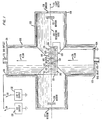
- FIG. 1 An illustrative embodiment of the present invention used for continuous wave operation of a SPER laser in a metal vapor is shown in FIG. 1.
- a plurality of metal strip electrodes 101-106 of, for example, cadmium, and having a thickness of from 0.1-1.0 mm, are positioned in tandem on an electrically insulating substrate 120 in such a manner as to leave a small gap (e.g., 1.5-2 mm) between each pair of adjacent strips.
- This electrode arrangement is then installed in a T-shaped gas cell comprising a longitudinal tube 125 and a transverse tube 12 (e.g., each of 35 cm length and 10 cm inside diameter).
- a high voltage supply 130 and a low voltage supply 132 are connectable in series across the first (101) and last (106) electrodes via switches 134 and 136, respectively.
- the high voltage supply typically provides a high power pulse (e.g., a few kV at 20-50 mA for "1 msec) to pre-ionize the gaps, after which low voltage supply 132 provides a lower power signal suitable for continuous wave operation.
- a signal which is longer in duration than a few milliseconds would be suitable for continuous wave operation.
- well-known cooling means (not shown) should be incorporated to prevent the electrodes from overheating and melting. This excitation produces a bright metal vapor plasma in each gap.
- Areas 141-145 in FIG. 1 depict the shape of the plasmas after they have expanded essentially hemispherically outward from the gaps into a background gas.
- each strip need not constitute a material which is vaporizable into a plasma. It is sufficient if the cathode ends constitute such a material and that the anode ends constitute a non-vaporizable material under the operating condition of the device. Moreover, strips of different vaporizable materials can be mixed within a single device so as to yield a multi-color source.
- Two dielectric spherical mirrors 150 and 151 are coated for maximum reflectivity at the desired lasing wavelength to form a resonator for the laser radiation.
- these mirrors are mounted near the ends of longitudinal tube 125 which contain windows 127 and 128.
- the optical axis 160 of this resonator is positioned parallel to and slightly above the row of electrodes.
- the output from this resonator, shown as arrow 170, is focused through suitable filters onto a suitable photodetector (not shown).
- Insulating substrate 120 is not essential to operation of the laser. In fact, substrate 120 can be eliminated without significantly affecting the laser output. It does, however, function as a structural support for the electrodes and can control the direction of plasma expansion to some extent. Illustratively, substrate 120 is mounted on a rod (not shown) which is translatably mounted through end plate 129 at one end of transverse tube 126 so as to allow positioning of the electrodes relative to axis 160.
- a gas inlet-170 and a gas outlet 172 are provided in end plates 129 and 131, respectively, at opposite ends of transverse tube 126.
- Background gas such as helium
- Arrows 174 show an illustrative direction of gas flow (e.g., transverse to resonator axis 160) which acts to cool the electrodes and allows for continuous wave operation.
- the direction of gas flow should be chosen so as to move the metal ions in the plasma away from the arc discharges in the regions of the gaps. To this end, the gas flow should at least be in the vicinity of the gaps.
- apertures 180 e.g., slots
- Background gas would thus flow not only around substrate 120 but also through it, thereby increasing the cooling interaction of the gas and the electrodes.
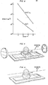
- FIGS. 5 and 6 Another alternative embodiment of our invention is to provide, as shown in FIGS. 5 and 6, means for containing the plasmas comprising at least one electrically insulating wall in the vicinity of each gap.
- four such walls form a rectangular box 190 surrounding the bottom of each plasma; in FIG. 6 a single wall forms a cylinder 192.
- the function of the containing means is three-fold: first to reduce the likelihood that particulates from the plasma are deposited on the laser mirrors by blocking line-of-sight paths from each gap to each mirror; second, to confine each plasma, thereby keeping it hotter and improving efficiency; and third, to electrically isolate adjacent arcs.
- the typical arc voltage drop ranged from 20 V at a current of 3 A to 15 V at a current of 8 A.
- the mass flow velocity of Cd vapor was measured to be about 2-3 cm/ms at a distance of 1-2 cm from the substrate 120.
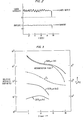
- FIG. 2 shows the continuous wave output of the laser operating for a duration of approximately one second. Operation for times longer than about 1 sec should include provision for better electrode cooling due to the relatively low melting point of Cd metal (320°C).
- the appearance of the continuous wave arc consisted of a bright core approximately 5 mm in diameter located in and above the electrode gap region and a weaker emitting hemisphere approximately 2 cm in extent. Measurements of the variation of emission intensities and populations of various species in the arc plasma were made as a function of distance from the substrate measured normal to the plane of the substrate.
- FIG. 3 shows the emission of an excited neutral line at .5085 ⁇ , an excited Cd ion line at .5378 ⁇ , and an excited neutral He line at .5875 um.
- the curve labled T e shows the variation of electron temperature with x.
- FIG. 4 shows the variation of Cd neutral and Cd ion species as a function of distance x from the substrate 120.
- the measurements were made by transmitting the emission from a He-Cd discharge through the arc plasma and measuring the absorption on transitions that terminate on the ground-state of these species. Since the results of FIG. 3 suggest a relatively low electron temperature, it can be argued that the Cd ion density of FIG. 4, N(Cd + ), is the same as the electron density, n ee
- the decrease in both N(Cd + ) and n e with x can be explained primarily by a three dimensional hemispherical expansion of those species. This is consistent with the fact that the decrease in N(Cd + ) and n e due to recombination can be shown to be negligible over the range of x of FIG. 2 for the flow velocities available in this experiment.
- a steady-state model was developed to describe the population of the upper laser level as a function of distance from the substrate 120.
- Two excitation mechanisms were considered. The first was electron collisional excitation from lower lying levels, but primarily from the neutral ground-state. It was found that electron excitation rates to the upper laser level, or even to a collection of levels above the upper laser level, followed by cascade, was not sufficient to explain the relatively high gain of .0025 cm -1 for the measured n e and relatively low electron temperature T e implied by the data of FIG. 3.
- the second excitation mechanism recombination to the upper laser level from the Cd + ground state, combined with radiative decay, gave results more consistent with the experimental results.
- Cd is the only metal in which cw arc lasers were attempted, it is expected that most of the 61 neutral transitions in 13 metals, ranging in wavelength from .941 ⁇ m to 5.46 ⁇ m, disclosed in our published papers to undergo pulsed recombination laser action in a SPER-type plasma arc device, should be capable of continuous wave laser output in a configuration of the type disclosed herein. Extension to transitions in ions, producing visible and even ultraviolet lasers, might also be possible. However, it would be desirable to raise the arc temperature to produce significant populations of double and triple ions from which single and double ion recombination lasers would originate.
Abstract
Description
- This invention relates to continuous wave operation of plasma excitation and recombination lasers.
- In Applied Physics Letters, Vol. 36, No. 8, page 615 (1980), W. T. Silfvast, L. H. Szeto and 0. R. Wood II describe a new electric discharge device developed for producing laser action in the atomic spectra of a number of metal vapors by a segmented plasma excitation and recombination (SPER) mechanism. This laser includes a number of narrow metal strips (of the lasing species) positioned end-to-end on an insulating substrate in such a way as to leave a small gap between each pair of adjacent strips. The strips are positioned in a laser cavity containing either a buffer gas (preferably) or a vacuum and typically are 1 mm thick, 2 mm wide, and 10 mm long. When a high-voltage, high-current pulse is applied to the end strips of this arrangement, a high-density metal-vapor ion plasma is formed in each gap. Once formed, these plasmas (consisting primarily of vaporized strip material) expand hemispherically, cool in the presence of the background gas (e.g., helium) at low pressure and recombine. Using this laser configuration, pulsed laser action was observed in the near infrared at more than seventy wavelengths between 0.29 and 3.95 m in 11 elements (Ag, Bi, C, Ca, Cd, Cu, In, Mg, Pb, Sn, Zn), 3 of which (Mg, Zn, In) had not been observed to oscillate in their neutral spectrum before. Some of these results are reported in the aforementioned APL article; others are reported by W. T. Silfvast et al in Applied Physics Letters, Vol. 39, No. 3, page 212 (1981) and in Optics Letters, Vol. 7, No. 1, page 34 (1982).
- The SPER laser is simple to construct, can be easily scaled in length and volume, has been shown to be capable of long life, and has the potential for high efficiency.
- In all of our prior work, however, the SPER lasers were operated in a pulsed mode; that is, the excitation means applied a relatively short duration (e.g., 5 msec) electrical pulse. Significantly longer duration electrical signals suitable for continuous wave operation would have generated excessive heat in the electrodes, ultimately causing them to melt. Had the electrodes been so damaged, of course, laser operation would no longer have been possible.
- In accordance with our invention, a continuous wave SPER laser includes at least two electrode strips having at least one gap therebetween which provides at least one_intervening discharge path; means for applying an electrical pump signal to the strips; at least a portion of the strips being fabricated from a material which is converted into a plasma as a result of the application of the pump signal, which plasma cools and recombines to generate laser radiation, characterized in that the pump signal is suitable for continuous wave operation and means are provided for flowing a background gas across the electrodes to cool them during the continuous wave operation. This technique is applicable to a wide range of visible and infrared recombination laser transitions already achieved in pulsed metal vapor arc plasmas and may also be extended to ion lasers, thereby producing visible and possibly ultraviolet laser outputs.
-
- FIG. 1 is a schematic of an illustrative embodiment of a continuous wave SPER laser in accordance with our invention;
- FIG. 2 is a graph showing an illustrative pump signal suitable for demonstrating continuous wave operation and the resulting laser light output;
- FIG. 3 is a graph of relative light intensity for various plasmas versus the distance x of the electrode strips from the resonator axis;
- FIG. 4 is a graph showing the variation of the density of the neutral and ion Cd species as a function of x; and
- FIGS. 5 and 6 show two illustrative embodiments of means in the vicinity of the electrode gaps for containing the plasmas.
- An illustrative embodiment of the present invention used for continuous wave operation of a SPER laser in a metal vapor is shown in FIG. 1. A plurality of metal strip electrodes 101-106 of, for example, cadmium, and having a thickness of from 0.1-1.0 mm, are positioned in tandem on an electrically
insulating substrate 120 in such a manner as to leave a small gap (e.g., 1.5-2 mm) between each pair of adjacent strips. This electrode arrangement is then installed in a T-shaped gas cell comprising alongitudinal tube 125 and a transverse tube 12 (e.g., each of 35 cm length and 10 cm inside diameter). Ahigh voltage supply 130 and alow voltage supply 132 are connectable in series across the first (101) and last (106) electrodes viaswitches low voltage supply 132 provides a lower power signal suitable for continuous wave operation. In general, a signal which is longer in duration than a few milliseconds would be suitable for continuous wave operation. For operation longer than about 1 sec, well-known cooling means (not shown) should be incorporated to prevent the electrodes from overheating and melting. This excitation produces a bright metal vapor plasma in each gap. Areas 141-145 in FIG. 1 depict the shape of the plasmas after they have expanded essentially hemispherically outward from the gaps into a background gas. - The entirety of each strip need not constitute a material which is vaporizable into a plasma. It is sufficient if the cathode ends constitute such a material and that the anode ends constitute a non-vaporizable material under the operating condition of the device. Moreover, strips of different vaporizable materials can be mixed within a single device so as to yield a multi-color source.
- Two dielectric
spherical mirrors longitudinal tube 125 which containwindows optical axis 160 of this resonator is positioned parallel to and slightly above the row of electrodes. The output from this resonator, shown asarrow 170, is focused through suitable filters onto a suitable photodetector (not shown). -
Insulating substrate 120 is not essential to operation of the laser. In fact,substrate 120 can be eliminated without significantly affecting the laser output. It does, however, function as a structural support for the electrodes and can control the direction of plasma expansion to some extent. Illustratively,substrate 120 is mounted on a rod (not shown) which is translatably mounted throughend plate 129 at one end oftransverse tube 126 so as to allow positioning of the electrodes relative toaxis 160. - A gas inlet-170 and a
gas outlet 172 are provided inend plates transverse tube 126. Background gas, such as helium, is coupled from a source (not shown) throughinlet 170 and is made to flow relatively rapidly (e.g., 500 1/min) across electrodes 101-106 tooutlet 172 and then to a gas pump (not shown).Arrows 174 show an illustrative direction of gas flow (e.g., transverse to resonator axis 160) which acts to cool the electrodes and allows for continuous wave operation. In general, the direction of gas flow should be chosen so as to move the metal ions in the plasma away from the arc discharges in the regions of the gaps. To this end, the gas flow should at least be in the vicinity of the gaps. - To enhance this effect it may be desirable to provide apertures 180 (e.g., slots) in
substrate 120 between the electrodes; i.e., in the gaps. Background gas would thus flow not only aroundsubstrate 120 but also through it, thereby increasing the cooling interaction of the gas and the electrodes. - Another alternative embodiment of our invention is to provide, as shown in FIGS. 5 and 6, means for containing the plasmas comprising at least one electrically insulating wall in the vicinity of each gap. In FIG. 5 four such walls form a
rectangular box 190 surrounding the bottom of each plasma; in FIG. 6 a single wall forms acylinder 192. The function of the containing means is three-fold: first to reduce the likelihood that particulates from the plasma are deposited on the laser mirrors by blocking line-of-sight paths from each gap to each mirror; second, to confine each plasma, thereby keeping it hotter and improving efficiency; and third, to electrically isolate adjacent arcs. - Laser action was investigated primarily upon the 6p3P - 6s3S transitions in Cd I occurring at 1.40, 1.43 and 1.44 pm. However, the 4f3F - 5d3D transition at 1.64 µm was also observed to undergo continuous wave laser action. All of these transitions have been previously observed to exhibit recombination laser action in a pulsed expanding plasma SPER-type laser device. The principal studies described herein were made on the strongest transition at 1.43 pm.
- Optimum laser output occurred at a He pressure of 5 Torr and, unlike prior art quasi-cw arc jet lasers requiring many kA of current, the optimum current was 4-6 A. Under these conditions, a laser output of 0.5 mW was measured using a highly-reflecting
mirror 150 at one end and a 1% transmissionoutput coupler mirror 151 at the other end of the resonator. The optimum height, x, from the bottom of the electrodes to theresonator axis 160 was x = 10 mm. However, laser action was observed to occur over a range of from x = 6 mm to 20 mm. In addition, the pressure variation over which laser action occurred ranged from 3 Torr to 10 Torr. The typical arc voltage drop ranged from 20 V at a current of 3 A to 15 V at a current of 8 A. At the optimum pressure of 5 Torr, the mass flow velocity of Cd vapor was measured to be about 2-3 cm/ms at a distance of 1-2 cm from thesubstrate 120. In general, it is desirable for the metal vapor mass flow to be at least this high to achieve continuous wave operation. - FIG. 2 shows the continuous wave output of the laser operating for a duration of approximately one second. Operation for times longer than about 1 sec should include provision for better electrode cooling due to the relatively low melting point of Cd metal (320°C).
- The appearance of the continuous wave arc consisted of a bright core approximately 5 mm in diameter located in and above the electrode gap region and a weaker emitting hemisphere approximately 2 cm in extent. Measurements of the variation of emission intensities and populations of various species in the arc plasma were made as a function of distance from the substrate measured normal to the plane of the substrate. FIG. 3 shows the emission of an excited neutral line at .5085 µτ, an excited Cd ion line at .5378 µτ, and an excited neutral He line at .5875 um. The curve labled Te shows the variation of electron temperature with x. It can be seen that the Cd I transition clearly dominates over the Cd II and He I transitions which are significantly higher in energy than the Cd I transition, suggesting that the arc electron temperature is relatively low. This result is not inconsistent with other measurements of arc temperatures which have suggested that temperatures in the range of 5000°K are typical.
- FIG. 4 shows the variation of Cd neutral and Cd ion species as a function of distance x from the
substrate 120. The measurements were made by transmitting the emission from a He-Cd discharge through the arc plasma and measuring the absorption on transitions that terminate on the ground-state of these species. Since the results of FIG. 3 suggest a relatively low electron temperature, it can be argued that the Cd ion density of FIG. 4, N(Cd+), is the same as the electron density, nee The decrease in both N(Cd+) and ne with x can be explained primarily by a three dimensional hemispherical expansion of those species. This is consistent with the fact that the decrease in N(Cd+) and ne due to recombination can be shown to be negligible over the range of x of FIG. 2 for the flow velocities available in this experiment. - A steady-state model was developed to describe the population of the upper laser level as a function of distance from the
substrate 120. Two excitation mechanisms were considered. The first was electron collisional excitation from lower lying levels, but primarily from the neutral ground-state. It was found that electron excitation rates to the upper laser level, or even to a collection of levels above the upper laser level, followed by cascade, was not sufficient to explain the relatively high gain of .0025 cm-1 for the measured ne and relatively low electron temperature Te implied by the data of FIG. 3. The second excitation mechanism, recombination to the upper laser level from the Cd+ ground state, combined with radiative decay, gave results more consistent with the experimental results. Using published recombination rates and fitting the measured gain observed at x = 10 mm, and also fitting the variation of emission of the highly excited Cd neutral state emitting at .5085 µm (the emission should be comparable to that of the upper laser level), a variation of Te with x was obtained as shown in FIG. 3. This result indicates a Te of 4000°K at x = 5 mm which drops to a value of 5000K at x = 20 mm. Such a drop is not unrealistic when it is considered that each electron and Cd ion has approximately 103 He atoms to interact and cool with during the expansion and that sufficient time is available to do this since it takes 300-500 µs for the ions to move from the cathode surface, where they are formed, to aposition 10 mm from the substrate, the location of optimum gain. Calculated hydrogen recombination rates were used in the model since those for Cd are not available. It is expected, however, that the use of Cd rates, if they were known, would shift the temperature up by only a small amount since it is expected that recombination rates for Cd would be slightly larger than those for hydrogen. - Therefore, it appears that recombination is responsible for the excitation of the continuous wave Cd SPER laser. The ions are probably formed primarily in the cathode spot regions, which are typically 10 pm regions of intense vaporization and emission located directly in front of the cathode surface. Such spots have been extensively studied, however, their exact properties are still not completely understood. It has been suggested that a high field region exists in the spots where significant ionization of the vaporized electrode material takes place. The more energetic ions are propelled outward from the spot and the less energetic ones are returned to the cathode to further heat the cathode surface and produce more vaporization. Such a model would be consistent with observations of emission in the present work in which the bright emission regions, other than the localized region at the cathode surface, would be due primarily to recombination (the excitation and ionization having occurred near the cathode surface in the cathode spot regions). Laseraction is not expected to occur at x = 5 mm or lower since the electron density nearer the cathode exceeds the upper limit above which laser action could occur on this transition due to electron collisional equilibration of the upper and lower laser levels.
- Although Cd is the only metal in which cw arc lasers were attempted, it is expected that most of the 61 neutral transitions in 13 metals, ranging in wavelength from .941 µm to 5.46 µm, disclosed in our published papers to undergo pulsed recombination laser action in a SPER-type plasma arc device, should be capable of continuous wave laser output in a configuration of the type disclosed herein. Extension to transitions in ions, producing visible and even ultraviolet lasers, might also be possible. However, it would be desirable to raise the arc temperature to produce significant populations of double and triple ions from which single and double ion recombination lasers would originate.
- Techniques such as the use of confinement plates of FIGS. 5 and 6 and magnetic fields to prevent the electron density from dropping much below the upper limit, should improve the efficiency of the laser and increase the power output.
Claims (11)
Applications Claiming Priority (2)
| Application Number | Priority Date | Filing Date | Title |
|---|---|---|---|
| US06/389,779 US4498182A (en) | 1982-06-18 | 1982-06-18 | Continuous wave sper laser |
| US389779 | 1982-06-18 |
Publications (3)
| Publication Number | Publication Date |
|---|---|
| EP0103079A2 true EP0103079A2 (en) | 1984-03-21 |
| EP0103079A3 EP0103079A3 (en) | 1986-11-26 |
| EP0103079B1 EP0103079B1 (en) | 1989-08-30 |
Family
ID=23539700
Family Applications (1)
| Application Number | Title | Priority Date | Filing Date |
|---|---|---|---|
| EP83105825A Expired EP0103079B1 (en) | 1982-06-18 | 1983-06-14 | Continuous wave recombination laser |
Country Status (6)
| Country | Link |
|---|---|
| US (1) | US4498182A (en) |
| EP (1) | EP0103079B1 (en) |
| JP (1) | JPS594090A (en) |
| CA (1) | CA1183933A (en) |
| DE (1) | DE3380508D1 (en) |
| GB (1) | GB2122023B (en) |
Families Citing this family (3)
| Publication number | Priority date | Publication date | Assignee | Title |
|---|---|---|---|---|
| US5394411A (en) * | 1994-02-16 | 1995-02-28 | University Of Maryland, College Park | Method for producing high intensity optical through x-ray waveguide and applications |
| US6804327B2 (en) * | 2001-04-03 | 2004-10-12 | Lambda Physik Ag | Method and apparatus for generating high output power gas discharge based source of extreme ultraviolet radiation and/or soft x-rays |
| US7749446B2 (en) * | 2004-10-02 | 2010-07-06 | Peterman Jr John William | Optimized gas cell |
Citations (2)
| Publication number | Priority date | Publication date | Assignee | Title |
|---|---|---|---|---|
| WO1982001622A1 (en) * | 1980-10-30 | 1982-05-13 | Western Electric Co | Recombination laser |
| WO1982003504A1 (en) * | 1981-04-06 | 1982-10-14 | Western Electric Co | A plasma-recombination laser having high power output |
Family Cites Families (1)
| Publication number | Priority date | Publication date | Assignee | Title |
|---|---|---|---|---|
| US4336506A (en) * | 1979-10-05 | 1982-06-22 | Bell Telephone Laboratories, Incorporated | Segmented plasma excitation-recombination laser |
-
1982
- 1982-06-18 US US06/389,779 patent/US4498182A/en not_active Expired - Lifetime
-
1983
- 1983-06-14 DE DE8383105825T patent/DE3380508D1/en not_active Expired
- 1983-06-14 EP EP83105825A patent/EP0103079B1/en not_active Expired
- 1983-06-15 GB GB08316246A patent/GB2122023B/en not_active Expired
- 1983-06-16 CA CA000430521A patent/CA1183933A/en not_active Expired
- 1983-06-17 JP JP58108023A patent/JPS594090A/en active Pending
Patent Citations (2)
| Publication number | Priority date | Publication date | Assignee | Title |
|---|---|---|---|---|
| WO1982001622A1 (en) * | 1980-10-30 | 1982-05-13 | Western Electric Co | Recombination laser |
| WO1982003504A1 (en) * | 1981-04-06 | 1982-10-14 | Western Electric Co | A plasma-recombination laser having high power output |
Non-Patent Citations (1)
| Title |
|---|
| Applied Physics Letters, vol. 36, no. 8, 15 April 1980, p. 615-617 * |
Also Published As
| Publication number | Publication date |
|---|---|
| EP0103079A3 (en) | 1986-11-26 |
| US4498182A (en) | 1985-02-05 |
| EP0103079B1 (en) | 1989-08-30 |
| JPS594090A (en) | 1984-01-10 |
| GB2122023B (en) | 1985-09-25 |
| GB2122023A (en) | 1984-01-04 |
| GB8316246D0 (en) | 1983-07-20 |
| CA1183933A (en) | 1985-03-12 |
| DE3380508D1 (en) | 1989-10-05 |
Similar Documents
| Publication | Publication Date | Title |
|---|---|---|
| US4730334A (en) | Ultraviolet metal ion laser | |
| US4937832A (en) | Methods and apparatus for producing soft x-ray laser in a capillary discharge plasma | |
| Silfvast et al. | Simple metal‐vapor recombination lasers using segmented plasma excitation | |
| Swingle et al. | Efficient narrowband electron beam pumped KrF laser for pulse‐compression studies | |
| US4369514A (en) | Recombination laser | |
| CA1164989A (en) | Recombination laser | |
| US4388720A (en) | External control of recombination rate for electron-ion recombination lasers | |
| EP0103079B1 (en) | Continuous wave recombination laser | |
| CA1206516A (en) | Segmented plasma excitation recombination light source | |
| US4504955A (en) | Low voltage operation of arc discharge devices | |
| US4395770A (en) | Segmented plasma excitation-recombination light source | |
| US4680770A (en) | Dual beam gas ion laser | |
| Macklin et al. | New recombination lasers in Li, Al, Ca and Cu in a segmented plasma device employing foil electrodes | |
| Qi et al. | Observed enhanced fluorescence at 2177, 2163, 1923, and 1620 Å in C iii by photoexcitation with Mn vi line radiation at 310 Å | |
| Silvfast et al. | New laser systems | |
| Fanning et al. | Mather‐type dense plasma focus as a new optical pump for short‐wavelength high‐power lasers | |
| Kamrukov et al. | Atomic xenon recombination laser excited by thermal ionizing radiation from a magnetoplasma compressor and discharge | |
| LASER | WT Silvfast and OR Wood I1 Be22 TeZephone Laboratories, HoZmdeZ, New Jersey 07733, USA Abstract.-Two new types of lasers, using electron-ion recombination as a pumping mechanism, are described. The first, a segmented-plasma-excitation-recombination (SPER) laser, is simple to construct and~ rovides ultraviolet, visible and infrared laser outuut from many metal vapors. The second, an | |
| Silfvast | VISIBLE LASERS | |
| Efthimiopoulos | Characteristics of a fast-discharge supersonic He plasma |
Legal Events
| Date | Code | Title | Description |
|---|---|---|---|
| PUAI | Public reference made under article 153(3) epc to a published international application that has entered the european phase |
Free format text: ORIGINAL CODE: 0009012 |
|
| AK | Designated contracting states |
Designated state(s): BE CH DE FR LI NL |
|
| PUAL | Search report despatched |
Free format text: ORIGINAL CODE: 0009013 |
|
| AK | Designated contracting states |
Kind code of ref document: A3 Designated state(s): BE CH DE FR LI NL |
|
| 17P | Request for examination filed |
Effective date: 19870518 |
|
| 17Q | First examination report despatched |
Effective date: 19880225 |
|
| GRAA | (expected) grant |
Free format text: ORIGINAL CODE: 0009210 |
|
| AK | Designated contracting states |
Kind code of ref document: B1 Designated state(s): BE CH DE FR LI NL |
|
| REF | Corresponds to: |
Ref document number: 3380508 Country of ref document: DE Date of ref document: 19891005 |
|
| ET | Fr: translation filed | ||
| PLBE | No opposition filed within time limit |
Free format text: ORIGINAL CODE: 0009261 |
|
| STAA | Information on the status of an ep patent application or granted ep patent |
Free format text: STATUS: NO OPPOSITION FILED WITHIN TIME LIMIT |
|
| 26N | No opposition filed | ||
| PGFP | Annual fee paid to national office [announced via postgrant information from national office to epo] |
Ref country code: CH Payment date: 19990323 Year of fee payment: 17 |
|
| PGFP | Annual fee paid to national office [announced via postgrant information from national office to epo] |
Ref country code: BE Payment date: 19990329 Year of fee payment: 17 |
|
| PGFP | Annual fee paid to national office [announced via postgrant information from national office to epo] |
Ref country code: NL Payment date: 20000524 Year of fee payment: 18 |
|
| PGFP | Annual fee paid to national office [announced via postgrant information from national office to epo] |
Ref country code: FR Payment date: 20000525 Year of fee payment: 18 |
|
| PG25 | Lapsed in a contracting state [announced via postgrant information from national office to epo] |
Ref country code: LI Free format text: LAPSE BECAUSE OF NON-PAYMENT OF DUE FEES Effective date: 20000630 Ref country code: CH Free format text: LAPSE BECAUSE OF NON-PAYMENT OF DUE FEES Effective date: 20000630 Ref country code: BE Free format text: LAPSE BECAUSE OF NON-PAYMENT OF DUE FEES Effective date: 20000630 |
|
| PGFP | Annual fee paid to national office [announced via postgrant information from national office to epo] |
Ref country code: DE Payment date: 20000630 Year of fee payment: 18 |
|
| BERE | Be: lapsed |
Owner name: WESTERN ELECTRIC CY INC. Effective date: 20000630 |
|
| REG | Reference to a national code |
Ref country code: CH Ref legal event code: PL |
|
| PG25 | Lapsed in a contracting state [announced via postgrant information from national office to epo] |
Ref country code: NL Free format text: LAPSE BECAUSE OF NON-PAYMENT OF DUE FEES Effective date: 20020101 |
|
| PG25 | Lapsed in a contracting state [announced via postgrant information from national office to epo] |
Ref country code: FR Free format text: LAPSE BECAUSE OF NON-PAYMENT OF DUE FEES Effective date: 20020228 |
|
| NLV4 | Nl: lapsed or anulled due to non-payment of the annual fee |
Effective date: 20020101 |
|
| PG25 | Lapsed in a contracting state [announced via postgrant information from national office to epo] |
Ref country code: DE Free format text: LAPSE BECAUSE OF NON-PAYMENT OF DUE FEES Effective date: 20020403 |