EP0102965B1 - Filter zur erweiterung der auflösung eines fernsehsignals in komponentenform - Google Patents
Filter zur erweiterung der auflösung eines fernsehsignals in komponentenform Download PDFInfo
- Publication number
- EP0102965B1 EP0102965B1 EP19830900641 EP83900641A EP0102965B1 EP 0102965 B1 EP0102965 B1 EP 0102965B1 EP 19830900641 EP19830900641 EP 19830900641 EP 83900641 A EP83900641 A EP 83900641A EP 0102965 B1 EP0102965 B1 EP 0102965B1
- Authority
- EP
- European Patent Office
- Prior art keywords
- filter
- signal
- efficients
- input signal
- samples
- Prior art date
- Legal status (The legal status is an assumption and is not a legal conclusion. Google has not performed a legal analysis and makes no representation as to the accuracy of the status listed.)
- Expired
Links
- 230000005540 biological transmission Effects 0.000 claims abstract description 8
- 238000001914 filtration Methods 0.000 claims description 16
- 230000003111 delayed effect Effects 0.000 claims description 8
- 238000005070 sampling Methods 0.000 description 20
- 230000002123 temporal effect Effects 0.000 description 17
- 238000001228 spectrum Methods 0.000 description 16
- 238000000034 method Methods 0.000 description 12
- 230000008569 process Effects 0.000 description 7
- 230000004044 response Effects 0.000 description 7
- 230000000694 effects Effects 0.000 description 6
- 230000006735 deficit Effects 0.000 description 3
- 238000010586 diagram Methods 0.000 description 3
- 230000001771 impaired effect Effects 0.000 description 3
- 230000006872 improvement Effects 0.000 description 3
- 230000001934 delay Effects 0.000 description 2
- 238000011045 prefiltration Methods 0.000 description 2
- 230000003595 spectral effect Effects 0.000 description 2
- 239000000654 additive Substances 0.000 description 1
- 230000000996 additive effect Effects 0.000 description 1
- 230000015556 catabolic process Effects 0.000 description 1
- 238000006243 chemical reaction Methods 0.000 description 1
- 230000006837 decompression Effects 0.000 description 1
- 230000007423 decrease Effects 0.000 description 1
- 230000007547 defect Effects 0.000 description 1
- 238000006731 degradation reaction Methods 0.000 description 1
- 230000002688 persistence Effects 0.000 description 1
- 230000009467 reduction Effects 0.000 description 1
- 238000010079 rubber tapping Methods 0.000 description 1
- 230000003068 static effect Effects 0.000 description 1
Images


Classifications
-
- H—ELECTRICITY
- H04—ELECTRIC COMMUNICATION TECHNIQUE
- H04N—PICTORIAL COMMUNICATION, e.g. TELEVISION
- H04N5/00—Details of television systems
- H04N5/14—Picture signal circuitry for video frequency region
- H04N5/20—Circuitry for controlling amplitude response
- H04N5/205—Circuitry for controlling amplitude response for correcting amplitude versus frequency characteristic
- H04N5/208—Circuitry for controlling amplitude response for correcting amplitude versus frequency characteristic for compensating for attenuation of high frequency components, e.g. crispening, aperture distortion correction
Definitions
- the present invention relates to a three dimensional transversal filter for extending the definition of a television video signal which is in component form.
- the transversal filter is a non-recursive filter in which the input signal is successively delayed and in which the output of the filter is formed by the summation of components obtained by weighting the variously delayed parts of the input signal.
- the filter is preferably used for filtering a television signal to be transmitted and hence such a filter is also present in a receiver for such a television signal.
- the present invention provides a three dimensional transversal non-recursive filter for filtering a television video signal in component form in which the input signal is successively delayed and in which the output of the filter is formed by the summation of components obtained by weighting the variously delayed parts of the input signal, characterised in that the filter structure has alternate co-efficients which are zero, the non-zero coefficients being in the form k/ 2 n where k and n are integers, said co-efficients being used to weight the delayed parts of the input signal.
- the filter structure is three-dimensional in that it has co-efficients which are situated over several fields and lines and horizontal samples of the sampled television video signal.
- PAL signals normally achieve about 3.8MHz of useful luminance bandwidth, 4.5MHz of 'clean' luminance bandwidth will be assumed as a figure which would represent an improvement (or at least comparability) with the performance of PAL, higher frequencies that 3.8MHz normally being impaired by cross-effects in typical decoders. Similarly, a figure of 1.3MHz will be assumed for the colour-difference channels, with a vertical resolution approaching half that of the luminance channel.
- each line of the luminance signal is compressed in time from 52 JlS to 40 ps, say, the transmission bandwidth increases proportionally.
- a luminance signal limited to a bandwidth of 4.5MHz would then pass through a 5.8MHz channel in this time-compressed form. At least 20 ps of the line would be available for the colour-difference signals, allowing a sequential colour-difference transmission of 2.2MHz bandwidth ( Figure 1). Filtering to 1.3MHz bandwidth would be applied in the receiver to improve S/N ratio. For a signal with this format, calculations show that the weighted S/N ratio in the colour channels would be improved by 5dB in comparison with pre-emphasised PAL (the luminance S/N ratio being virtually unchanged).
- the analogue television signal represents a dynamic scene which has been sampled in two dimensions. It has been sampled vertically by the line structure, and temporally by the field structure. Any sampling process generates spurious spectral components which can give rise to aliasing impairment of the baseband spectrum through intermodulation with the sampling frequency.
- a frequency f produces an intermodulation component (f s- f) where f s is the sampling frequency. This gives rise to a repeat of the baseband spectrum centred on the sample frequency f. in the manner shown in Figure 3.
- the baseband spectrum must be low-pass filtered to remove frequencies exceeding f s /2.
- a similar low-pass filter must be used after D/A conversion so that only the baseband spectrum is reproduced at the output ( Figure 4).
- the line-interlace structure considered as a sampling frequency, must be treated in two dimensions.
- the lines sample the scene vertically, but are also displaced along the temporal axis (i.e. between adjacent fields). Therefore we must introduce the concept of a two-dimensional frequency plan as shown in Figure 5.
- the interlaced line structure is represented by a point in this plane at 312s cycles/picture height, and 25 Hz temporal frequency.
- the baseband signal is centred on the point (0, 0) and is unrestricted in extent, except by the sampling aperture (that is, the spot-size and persistence), there being no pre-filter either vertically or temporally.
- the effect of the sampling process is to introduce a repeat baseband spectrum on the site of the sampling frequency.
- vertical frequencies exceeding 1564 c/ph or temporal frequencies exceeding 12: Hz could give rise to significant alias defects unless pre-filtering is applied.
- the repeat spectrum will be apparent in the display unless post-filtering is also applied-this is merely the visibility of the interlace line-structure familiar in all television pictures.
- the simplest arrangement for the removal of vertical and temporal aliasing would be to introduce separate filters in the vertical and temporal directions, as shown in Figure 6.
- a combined vertical/temporal filter can produce the result shown in Figure 7, in which a peak resolution of 312s c/ph and 25 Hz is achieved. This characteristic approximates that of the human eye which can perceive high spatial resolution only in static scenes. It is clear that a conventional line-interlace structure (3122 lines/field) can support a vertical resolution of 3122 c/ph but does not do so if the scene is sampled directly with line-interlace scanning.
- This signal could be displayed on a conventional interlace monitor, which would then show improved aliasing characteristics.
- the line structure would remain visible however, due to the presence of the repeat spectrum at 312 2 c/ph/25 Hz.
- the full potential of the signal can be realised only if a post-filter is included prior to the display.
- the repeat spectrum is unavoidable in a 31212-lines/field interlace display, but the post-filter has the effect of interpolating the lines which were originally dropped, so as to recreate the 625 lines/field signal. Indeed, it may be shown that the functions of post-filtering and line interpolation are mathematically equivalent.
- the procedure just described provides a transmission signal which may be viewed either on a conventional display, or with enhanced resolution by including the necessary filtering. It therefore represents a compatible extension to resolution, the costs of which are borne only by users who wish to pay for the improved picture quality.
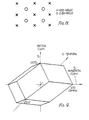
- This sample structure must be analysed in three dimensions, the samples being displaced horizontally, vertically and temporally. Consequently, the repeat spectra generated by the sample structure occur in three dimensional frequency space.
- Suitable three-dimensional filtering can (in principle) then create an alias free (unity gain) region extending to 9MHz horizontally, 3122 c/ph vertically and 25 Hz vertically, as shown in Figure 9.
- the source coding must be a 625 lines/field sequential scan signal, with alternate lines being dropped after the pre-filtering process, thereby creating a compatible field interlace structure.
- the extended-definition receiver would include a similar post-filter/interpolator prior to a 625-line sequential display.
- the sample impulses at a 9MHz rate can pass through an analogue Nyquist channel of 4.5MHz bandwidth without impairment, or through a 5.85MHz channel when time compressed from 52 JlS to 40 Its per line. It is less than obvious that the technique also improves the spectral efficiency of the signal, or indeed that the extended definition arises directly as a result of this improvement.
- Conventional signals contain a series of gaps in the spectrum which carry only high-frequency diagonal information. When high-frequency diagonals are excluded, as in Figure 9 these gaps become available to carry more useful information.
- the effect of the 3-D sampling process described is to deliberately alias useful high-frequency information into these gaps.
- the original spectrum can then be truncated, in the safe knowledge that high frequencies are carried elsewhere in the signal.
- the post-filter/ interpolator restores the folded energy to its rightful position at high frequency, thereby recreating the original spectrum.
- sampling density i.e. number of samples per unit space-time volume-defines a frequency volume which cannot be exceeded by the signal spectrum for error-free reconstruction.
- the particular arrangement of samples (the sampling lattice) restricts the choice for the shape of the approprate frequency volume.
- a class of linear filters has been designed which, achieve the required resolution exchange without non-linear distortion.
- the filters have the following important properties:-
- the horizontal-vertical response i.e. the stationary picture response
- the horizontaltemporal response are shown for a filter with these coefficient values in Figure 12.
- the filter described above may be used with television signals using the multiplexed analogue component system described previously or with component television signals in digital form. Further, it may be used for broadcast links in general rather than public direct broadcast by satellite.
- this filter is a linear filter and thus cross-over effects present in non-linear filters are avoided.
- the above filter could be altered to enhance only the horizontal resolution.
Landscapes
- Engineering & Computer Science (AREA)
- Multimedia (AREA)
- Signal Processing (AREA)
- Television Systems (AREA)
Claims (4)
Applications Claiming Priority (2)
| Application Number | Priority Date | Filing Date | Title |
|---|---|---|---|
| GB8202622 | 1982-01-29 | ||
| GB8202622 | 1982-01-29 |
Publications (2)
| Publication Number | Publication Date |
|---|---|
| EP0102965A1 EP0102965A1 (de) | 1984-03-21 |
| EP0102965B1 true EP0102965B1 (de) | 1986-09-17 |
Family
ID=10527978
Family Applications (1)
| Application Number | Title | Priority Date | Filing Date |
|---|---|---|---|
| EP19830900641 Expired EP0102965B1 (de) | 1982-01-29 | 1983-01-31 | Filter zur erweiterung der auflösung eines fernsehsignals in komponentenform |
Country Status (4)
| Country | Link |
|---|---|
| EP (1) | EP0102965B1 (de) |
| JP (1) | JPS59500158A (de) |
| DE (1) | DE3366164D1 (de) |
| WO (1) | WO1983002704A1 (de) |
Families Citing this family (6)
| Publication number | Priority date | Publication date | Assignee | Title |
|---|---|---|---|---|
| DE3673999D1 (de) * | 1986-06-14 | 1990-10-11 | Ant Nachrichtentech | Verfahren zum uebertragen von fernsehsignalen mit verbesserter bildqualitaet. |
| EP0257129B1 (de) * | 1986-08-29 | 1990-04-11 | ANT Nachrichtentechnik GmbH | Verfahren zur Wiedergabe von Fernsehsignalen mit verbesserter Bildqualität |
| US4866519A (en) * | 1987-09-02 | 1989-09-12 | Scientific Atlanta, Inc. | Method and apparatus for increasing the vertical definition of a transmitted television signal |
| US4965661A (en) * | 1988-08-04 | 1990-10-23 | Scientific-Atlanta, Inc. | Method and apparatus for increasing the definiton of an NTSC video signal using an augmentation channel |
| US5053859A (en) * | 1987-09-02 | 1991-10-01 | Scientific-Atlanta, Inc. | High definition B-MAC television signal transmission system |
| US4989091A (en) * | 1988-11-16 | 1991-01-29 | Scientific-Atlanta, Inc. | Scan converter for a high definition television system |
Family Cites Families (1)
| Publication number | Priority date | Publication date | Assignee | Title |
|---|---|---|---|---|
| GB2055002B (en) * | 1979-07-12 | 1983-08-03 | Rank Organisation Ltd | Video signal processing apparatus |
-
1983
- 1983-01-31 WO PCT/GB1983/000022 patent/WO1983002704A1/en not_active Ceased
- 1983-01-31 EP EP19830900641 patent/EP0102965B1/de not_active Expired
- 1983-01-31 JP JP83500683A patent/JPS59500158A/ja active Pending
- 1983-01-31 DE DE8383900641T patent/DE3366164D1/de not_active Expired
Also Published As
| Publication number | Publication date |
|---|---|
| JPS59500158A (ja) | 1984-01-26 |
| EP0102965A1 (de) | 1984-03-21 |
| WO1983002704A1 (en) | 1983-08-04 |
| DE3366164D1 (en) | 1986-10-23 |
Similar Documents
| Publication | Publication Date | Title |
|---|---|---|
| US4558347A (en) | Progressive scan television system employing vertical detail enhancement | |
| US4621286A (en) | Spatial-temporal frequency interleaved processing of a television signal with reduced amplitude interleaved sections | |
| US4967272A (en) | Bandwidth reduction and multiplexing of multiple component TV signals | |
| US5274449A (en) | Letterbox television signal with edge regions containing transformed pixel values | |
| EP0638220B1 (de) | Videosignalkodierung | |
| US4683490A (en) | Video signal processing apparatus | |
| WO1989002204A1 (en) | Method and apparatus for increasing the vertical definition of a transmitted television signal | |
| EP0102965B1 (de) | Filter zur erweiterung der auflösung eines fernsehsignals in komponentenform | |
| EP0148255A1 (de) | Verfahren und anordnung für vertikale farbauflösungserweiterung. | |
| US4635098A (en) | Method and system for improved reconstruction of video images in line sequential chroma format | |
| JPH0686236A (ja) | テレビジョン信号処理装置 | |
| Ouellet et al. | Sampling and reconstruction of NTSC video signals at twice the color subcarrier frequency | |
| US5053859A (en) | High definition B-MAC television signal transmission system | |
| US5227879A (en) | Apparatus for transmitting an extended definition TV signal having compatibility with a conventional TV system | |
| EP0163512B1 (de) | Raumzeitliche Signalverarbeitung mit Frequenzverkammung eines Fernsehsignals | |
| US6424384B1 (en) | Method and apparatus for improved signal filtering | |
| GB2166021A (en) | Transmitting television signals | |
| EP0571362A1 (de) | B-mac-fernsehsignalübertragungssystem hoher auflösung | |
| GB2262859A (en) | Letterbox television signal with chrominance helper signal | |
| EP0329976A2 (de) | Fernsehsystem mit mehreren analogen Komponenten | |
| US4616251A (en) | Progressive scan television system employing a comb filter | |
| Girod et al. | Vertical sampling rate decimation and line-offset decimation of colour difference signals | |
| Arragon et al. | Instrumentation of a compatible HD-MAC coding system using DATV | |
| CA1136264A (en) | Method and apparatus for pcm-encoding ntsc color television at sub-nyquist rate | |
| Itoh et al. | Simultaneous transmission system for two video signals |
Legal Events
| Date | Code | Title | Description |
|---|---|---|---|
| PUAI | Public reference made under article 153(3) epc to a published international application that has entered the european phase |
Free format text: ORIGINAL CODE: 0009012 |
|
| 17P | Request for examination filed |
Effective date: 19831208 |
|
| AK | Designated contracting states |
Designated state(s): DE FR GB NL |
|
| GRAA | (expected) grant |
Free format text: ORIGINAL CODE: 0009210 |
|
| AK | Designated contracting states |
Kind code of ref document: B1 Designated state(s): DE FR GB NL |
|
| REF | Corresponds to: |
Ref document number: 3366164 Country of ref document: DE Date of ref document: 19861023 |
|
| ET | Fr: translation filed | ||
| PGFP | Annual fee paid to national office [announced via postgrant information from national office to epo] |
Ref country code: NL Payment date: 19870131 Year of fee payment: 5 |
|
| PLBE | No opposition filed within time limit |
Free format text: ORIGINAL CODE: 0009261 |
|
| STAA | Information on the status of an ep patent application or granted ep patent |
Free format text: STATUS: NO OPPOSITION FILED WITHIN TIME LIMIT |
|
| 26N | No opposition filed | ||
| PG25 | Lapsed in a contracting state [announced via postgrant information from national office to epo] |
Ref country code: NL Effective date: 19880801 |
|
| NLV4 | Nl: lapsed or anulled due to non-payment of the annual fee | ||
| GBPC | Gb: european patent ceased through non-payment of renewal fee | ||
| PG25 | Lapsed in a contracting state [announced via postgrant information from national office to epo] |
Ref country code: FR Free format text: LAPSE BECAUSE OF NON-PAYMENT OF DUE FEES Effective date: 19880930 |
|
| PG25 | Lapsed in a contracting state [announced via postgrant information from national office to epo] |
Ref country code: DE Effective date: 19881001 |
|
| PG25 | Lapsed in a contracting state [announced via postgrant information from national office to epo] |
Ref country code: GB Free format text: LAPSE BECAUSE OF NON-PAYMENT OF DUE FEES Effective date: 19881122 |
|
| REG | Reference to a national code |
Ref country code: FR Ref legal event code: ST |