EP0102959B1 - Priority flow control system - Google Patents
Priority flow control system Download PDFInfo
- Publication number
- EP0102959B1 EP0102959B1 EP83900400A EP83900400A EP0102959B1 EP 0102959 B1 EP0102959 B1 EP 0102959B1 EP 83900400 A EP83900400 A EP 83900400A EP 83900400 A EP83900400 A EP 83900400A EP 0102959 B1 EP0102959 B1 EP 0102959B1
- Authority
- EP
- European Patent Office
- Prior art keywords
- priority
- control
- flow control
- flow
- fluid
- Prior art date
- Legal status (The legal status is an assumption and is not a legal conclusion. Google has not performed a legal analysis and makes no representation as to the accuracy of the status listed.)
- Expired
Links
- 239000012530 fluid Substances 0.000 claims description 68
- 238000006073 displacement reaction Methods 0.000 description 16
- 230000036316 preload Effects 0.000 description 11
- 230000001276 controlling effect Effects 0.000 description 8
- 230000009471 action Effects 0.000 description 7
- 230000008901 benefit Effects 0.000 description 5
- 230000007935 neutral effect Effects 0.000 description 4
- 238000013459 approach Methods 0.000 description 3
- 230000000903 blocking effect Effects 0.000 description 2
- 238000010276 construction Methods 0.000 description 2
- 230000003247 decreasing effect Effects 0.000 description 2
- 230000001105 regulatory effect Effects 0.000 description 2
- 230000009286 beneficial effect Effects 0.000 description 1
- 230000000694 effects Effects 0.000 description 1
- 230000010354 integration Effects 0.000 description 1
- 230000007246 mechanism Effects 0.000 description 1
- 230000009467 reduction Effects 0.000 description 1
- 230000004044 response Effects 0.000 description 1
- 238000012163 sequencing technique Methods 0.000 description 1
- 238000011144 upstream manufacturing Methods 0.000 description 1
Images
Classifications
-
- F—MECHANICAL ENGINEERING; LIGHTING; HEATING; WEAPONS; BLASTING
- F15—FLUID-PRESSURE ACTUATORS; HYDRAULICS OR PNEUMATICS IN GENERAL
- F15B—SYSTEMS ACTING BY MEANS OF FLUIDS IN GENERAL; FLUID-PRESSURE ACTUATORS, e.g. SERVOMOTORS; DETAILS OF FLUID-PRESSURE SYSTEMS, NOT OTHERWISE PROVIDED FOR
- F15B11/00—Servomotor systems without provision for follow-up action; Circuits therefor
- F15B11/16—Servomotor systems without provision for follow-up action; Circuits therefor with two or more servomotors
- F15B11/161—Servomotor systems without provision for follow-up action; Circuits therefor with two or more servomotors with sensing of servomotor demand or load
- F15B11/162—Servomotor systems without provision for follow-up action; Circuits therefor with two or more servomotors with sensing of servomotor demand or load for giving priority to particular servomotors or users
-
- F—MECHANICAL ENGINEERING; LIGHTING; HEATING; WEAPONS; BLASTING
- F15—FLUID-PRESSURE ACTUATORS; HYDRAULICS OR PNEUMATICS IN GENERAL
- F15B—SYSTEMS ACTING BY MEANS OF FLUIDS IN GENERAL; FLUID-PRESSURE ACTUATORS, e.g. SERVOMOTORS; DETAILS OF FLUID-PRESSURE SYSTEMS, NOT OTHERWISE PROVIDED FOR
- F15B11/00—Servomotor systems without provision for follow-up action; Circuits therefor
- F15B11/16—Servomotor systems without provision for follow-up action; Circuits therefor with two or more servomotors
- F15B11/161—Servomotor systems without provision for follow-up action; Circuits therefor with two or more servomotors with sensing of servomotor demand or load
- F15B11/163—Servomotor systems without provision for follow-up action; Circuits therefor with two or more servomotors with sensing of servomotor demand or load for sharing the pump output equally amongst users or groups of users, e.g. using anti-saturation, pressure compensation
-
- F—MECHANICAL ENGINEERING; LIGHTING; HEATING; WEAPONS; BLASTING
- F15—FLUID-PRESSURE ACTUATORS; HYDRAULICS OR PNEUMATICS IN GENERAL
- F15B—SYSTEMS ACTING BY MEANS OF FLUIDS IN GENERAL; FLUID-PRESSURE ACTUATORS, e.g. SERVOMOTORS; DETAILS OF FLUID-PRESSURE SYSTEMS, NOT OTHERWISE PROVIDED FOR
- F15B2211/00—Circuits for servomotor systems
- F15B2211/20—Fluid pressure source, e.g. accumulator or variable axial piston pump
- F15B2211/205—Systems with pumps
- F15B2211/2053—Type of pump
-
- F—MECHANICAL ENGINEERING; LIGHTING; HEATING; WEAPONS; BLASTING
- F15—FLUID-PRESSURE ACTUATORS; HYDRAULICS OR PNEUMATICS IN GENERAL
- F15B—SYSTEMS ACTING BY MEANS OF FLUIDS IN GENERAL; FLUID-PRESSURE ACTUATORS, e.g. SERVOMOTORS; DETAILS OF FLUID-PRESSURE SYSTEMS, NOT OTHERWISE PROVIDED FOR
- F15B2211/00—Circuits for servomotor systems
- F15B2211/30—Directional control
- F15B2211/305—Directional control characterised by the type of valves
- F15B2211/30525—Directional control valves, e.g. 4/3-directional control valve
- F15B2211/3053—In combination with a pressure compensating valve
- F15B2211/30535—In combination with a pressure compensating valve the pressure compensating valve is arranged between pressure source and directional control valve
-
- F—MECHANICAL ENGINEERING; LIGHTING; HEATING; WEAPONS; BLASTING
- F15—FLUID-PRESSURE ACTUATORS; HYDRAULICS OR PNEUMATICS IN GENERAL
- F15B—SYSTEMS ACTING BY MEANS OF FLUIDS IN GENERAL; FLUID-PRESSURE ACTUATORS, e.g. SERVOMOTORS; DETAILS OF FLUID-PRESSURE SYSTEMS, NOT OTHERWISE PROVIDED FOR
- F15B2211/00—Circuits for servomotor systems
- F15B2211/50—Pressure control
- F15B2211/505—Pressure control characterised by the type of pressure control means
- F15B2211/50509—Pressure control characterised by the type of pressure control means the pressure control means controlling a pressure upstream of the pressure control means
- F15B2211/50536—Pressure control characterised by the type of pressure control means the pressure control means controlling a pressure upstream of the pressure control means using unloading valves controlling the supply pressure by diverting fluid to the return line
-
- F—MECHANICAL ENGINEERING; LIGHTING; HEATING; WEAPONS; BLASTING
- F15—FLUID-PRESSURE ACTUATORS; HYDRAULICS OR PNEUMATICS IN GENERAL
- F15B—SYSTEMS ACTING BY MEANS OF FLUIDS IN GENERAL; FLUID-PRESSURE ACTUATORS, e.g. SERVOMOTORS; DETAILS OF FLUID-PRESSURE SYSTEMS, NOT OTHERWISE PROVIDED FOR
- F15B2211/00—Circuits for servomotor systems
- F15B2211/50—Pressure control
- F15B2211/57—Control of a differential pressure
-
- F—MECHANICAL ENGINEERING; LIGHTING; HEATING; WEAPONS; BLASTING
- F15—FLUID-PRESSURE ACTUATORS; HYDRAULICS OR PNEUMATICS IN GENERAL
- F15B—SYSTEMS ACTING BY MEANS OF FLUIDS IN GENERAL; FLUID-PRESSURE ACTUATORS, e.g. SERVOMOTORS; DETAILS OF FLUID-PRESSURE SYSTEMS, NOT OTHERWISE PROVIDED FOR
- F15B2211/00—Circuits for servomotor systems
- F15B2211/60—Circuit components or control therefor
- F15B2211/605—Load sensing circuits
- F15B2211/6051—Load sensing circuits having valve means between output member and the load sensing circuit
- F15B2211/6052—Load sensing circuits having valve means between output member and the load sensing circuit using check valves
-
- F—MECHANICAL ENGINEERING; LIGHTING; HEATING; WEAPONS; BLASTING
- F15—FLUID-PRESSURE ACTUATORS; HYDRAULICS OR PNEUMATICS IN GENERAL
- F15B—SYSTEMS ACTING BY MEANS OF FLUIDS IN GENERAL; FLUID-PRESSURE ACTUATORS, e.g. SERVOMOTORS; DETAILS OF FLUID-PRESSURE SYSTEMS, NOT OTHERWISE PROVIDED FOR
- F15B2211/00—Circuits for servomotor systems
- F15B2211/60—Circuit components or control therefor
- F15B2211/65—Methods of control of the load sensing pressure
-
- Y—GENERAL TAGGING OF NEW TECHNOLOGICAL DEVELOPMENTS; GENERAL TAGGING OF CROSS-SECTIONAL TECHNOLOGIES SPANNING OVER SEVERAL SECTIONS OF THE IPC; TECHNICAL SUBJECTS COVERED BY FORMER USPC CROSS-REFERENCE ART COLLECTIONS [XRACs] AND DIGESTS
- Y10—TECHNICAL SUBJECTS COVERED BY FORMER USPC
- Y10T—TECHNICAL SUBJECTS COVERED BY FORMER US CLASSIFICATION
- Y10T137/00—Fluid handling
- Y10T137/8593—Systems
- Y10T137/87169—Supply and exhaust
- Y10T137/87177—With bypass
- Y10T137/87185—Controlled by supply or exhaust valve
-
- Y—GENERAL TAGGING OF NEW TECHNOLOGICAL DEVELOPMENTS; GENERAL TAGGING OF CROSS-SECTIONAL TECHNOLOGIES SPANNING OVER SEVERAL SECTIONS OF THE IPC; TECHNICAL SUBJECTS COVERED BY FORMER USPC CROSS-REFERENCE ART COLLECTIONS [XRACs] AND DIGESTS
- Y10—TECHNICAL SUBJECTS COVERED BY FORMER USPC
- Y10T—TECHNICAL SUBJECTS COVERED BY FORMER US CLASSIFICATION
- Y10T137/00—Fluid handling
- Y10T137/8593—Systems
- Y10T137/87169—Supply and exhaust
- Y10T137/87233—Biased exhaust valve
Definitions
- This invention relates generally to fluid control valves provided with positive and negative load compensation.
- this invention relates to pressure compensated direction and flow control valves, the positive and negative load compensators of which are controlled by a single amplifying pilot valve stage.
- this invention relates to pilot operated pressure compensated controls of direction control valves, used in control of positive and negative load, which permit variation in the level of control differential across metering orifices of the valve spool, while this control differential is automatically maintained constant at each controlled level.
- this invention relates to pilot operated pressure compensated controls of direction control valves, which provide a priority feature for specific valves by controlling the pressure differential of all of the nonpriority valves.
- Closed center fluid control valves pressure compensated for control of positive and negative loads, are desirable for a number of reasons. They permit load control with reduced power losses and therefore, increased system efficiency. They also permit simultaneous proportional control of multiple positive and negative loads.
- Such fluid control valves are shown in US-A-4180098 and also in US-A-4222409.
- the valves of those patents although capable of proportional control of positive and negative loads, use for such control the energy directly transmitted through the load pressure sensing ports, which not only attenuate the control signals, but limit the response of the control.
- Those valves also automatically maintain a constant pressure differential across metering orifices in control of both positive and negative loads.
- the priority feature is obtained by throttling the fluid flow to the downstream valves, so that the priority valve is always assured of the required flow, once the maximum flow output of the system pump is reached. Also in those valves the construction of the priority valve is substantially different from the nonpriority valves and the priority valve must work in a series type circuit.
- US-A-4231396 discloses a closed centre load responsive fluid control valve assembly supplied with pressurized fluid, the valve assembly having control orifice means interposed between the fluid supply chamber and the load chamber, and first fluid flow control means to maintain a pressure differential across the control orifice means.
- Another object of this invention is to provide a priority flow control system, in which the pressure differential of the nonpriority valves is progressively lowered once the system pump reaches its maximum flow output, automatically providing the priority valve with the required flow.
- a priority flow control system supplied from a source of pressure fluid and connected to exhaust means, the priority flow control system including a priority valve assembly operable to control a load and at least one other her non-priority valve assembly operable to control a further load, each valve assembly having a housing connected to a fluid motor, control orifice means in the housing interposed between the source of pressure fluid and the fluid motor, fluid flow control means in the housing, first control means operable through the fluid flow control means to maintain a pressure differential across the control orifice means at a controlled constant level; characterized by second control means of the non-priority valve assembly having first means responsive to maximum fluid flow from the source of pressure fluid and second means operable through the fluid flow control means and the first control means to vary the level of the constant pressure differential so that the level of the constant pressure differential is progressively lowered by the second means once fluid flow from the source of pressure fluid reaches its maximum flow output and flow demand of the flow control system exceeds the maximum flow output.
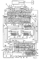
- a priority flow control valve generally designated as 10, is shown interposed between diagrammatically shown fluid motor 11, driving load W and a pump 12 of a fixed displacement or variable displacement type, driven by a prime mover, not shown. Fluid flow from the pump 12 to priority flow control valve 10 and a circuit of diagrammatically shown flow control valve 13 is regulated by pump flow control 14. If pump 12 is of a fixed displacement type, pump flow control 14 is a differential pressure relief valve, which, in a well known manner, by bypassing fluid from pump 12 to a reservoir 15, maintains discharge pressure of pump 12 at a level, higher by a constant pressure differential, than load pressure developed in fluid motor 11.
- pump flow control 14 is a differential pressure compensator, well known in the art, which by changing displacement of pump 12, maintains discharge pressure of pump 12 at a level, higher by a constant pressure differential, than load pressure developed in fluid motor 11.
- the pump flow control 14 may also be a maximum pressure compensator or relief valve, which maintains the discharge pressure of the pump 12 at a maximum constant pressure level during operation of the system.
- the priority flow control valve 10 is of a four way type and has a housing 16 provided with a bore 17, axially guiding a valve spool 18.
- the valve spool 18 is equipped with lands 19, 20 and 21, which in neutral position of the valve spool 18, as shown in the drawing, isolate a fluid supply chamber 22, load chambers 23 and 24 and outlet chambers 25 and 26.
- Lands 19, 20 and 21, of valve spool 18, are provided with metering slots 27, 28, 29 and 30 and signal slots 31, 32, 33 and 34.
- Negative load sensing ports 35 and 36 are positioned between load chambers 23 and 24 and outlet chambers 26 and 25.
- Positive load sensing ports 37 and 38 are located between supply chamber 22 and load chambers 23 and 24.
- the pump 12 through its discharge line 43, is connected to an inlet chamber 44.
- the inlet chamber 44 is connected through positive load throttling slots 45, on control spool 40, provided with throttling edges 46, with the fluid supply chamber 22.
- Bore 47 axially guides the control spool 40, which is biased by control spring 48, contained in control space 49, towards position as shown.
- the control spool 40 at one end projects into control space 49, the .other end projecting into chamber 50, connected to the reservoir 15.
- a pilot valve assembly generally designated as 51, comprises a housing 52, provided with a bore 53, slidably guiding a pilot valve spool 54 and a free floating piston 55.
- the pilot valve spool 54 is provided with lands 56, 57 and 58, defining annular spaces 59 and 60. Annular space 61 is provided within the housing 52 and communicates directly with bore 53.
- the free floating piston 55 is provided with a land 62, which defines annular spaces 63 and 64 and is provided with extension 65 selectively engageable with land 58 of the pilot valve spool 54.
- the pilot valve spool 54 at one end projects into control space 66 and engages, with its land 56 and spring retainer 67, a pilot valve spring 68.
- Control space 66 communicates through lines 69 and 69b and a controller, generally designated as 66a, and through line 69a with check valve 70 and through line 69 with check valve 71.
- the check valve 70 is connected by passage 72 with positive load sensing ports 37 and 38.
- the check valve 71 communicates through line 73 with the outlet chamber 25.
- Annular space 61, of the pilot valve assembly 51 communicates through line 74 with control space 49 and also communicates, through leakage orifice 75, with annular space 60, which in turn is connected to reservoir 15.
- Annular space 59 communicates through line 76 with discharge line 43.
- Annular space 64 is connected by line 81 with the supply chamber 22.
- Annular space 63 is connected by line 82 and passage 83 with negative load sensing ports 36 and 35.
- Positive load sensing ports 37 and 38 are connected through passage 72, line 84 and a check valve 85 and a signal line 86 with the pump flow control 14.
- Control space 66 is connected through a flow control, generally designated as 87, with the reservoir 15.
- Flow control 87 is a flow control device, passing a constant flow from control space 66 to the reservoir 15.
- the load chambers 23 and 24 are connected, for one way fluid flow, by check valves 89 and 90, to schematically shown system reservoir, which also might be a pressurized exhaust manifold of the entire control system, as shown in the drawing.
- the flow control, generally designated as 87 is interposed between control space 66 and the system reservoir 15 and comprises a housing 91, provided with a bore 92, guiding a flow control spool 93, which defines spaces 94 and 95 and which is biased by a spring 96.
- the flow control spool 93 is provided with lands 97 and 98, defining annular space 99, which is connected by line 100 with control space 66.
- the flow control spool 93 is also provided with throttling slots 101 and leakage orifice 102, which communicates through passages 103 and 104, space 95 with space 94, space 94 being connected by line 105 with system reservoir 15.
- the controller is interposed between control space 66 and check valve 70, communicating with positive load sensing ports 37 and 38 and comprises schematically shown variable orifice section 106, operated by an actuating section 107.
- the actuating section 107 is provided with a piston 108, guided in a housing 109, defining spaces 110 and 111 and biased towards position as shown by a spring 112. Space 110 is subjected to an external fluid power control signal 113, while space 111 is subjected to a control signal 114.
- Schematically shown nonpriority cortrol valves are identical to the priority flow control valve 10 and are each provided with an identical pilot valve section 51, flow control section 87 and controllers 117 and 118, similar to the controller 66a.
- the controller 117 is provided with a piston 119, defining spaces 120 and 121, is biased by a spring 122 and is operably connected to a variable orifice section 123.
- Space 120 is connected by line 124 to discharge line 43 while space 121 is connected by a line 125 and lines 86a and 86 to the check valve logic circuit, sensing maximum positive load pressure of the priority control system.
- the controller 118 is provided with a piston 126, defining spaces 127 and 128, is biased by a spring 129 and is operably connected to a variable orifice section 130.
- Space 127 is connected by line 131 to discharge line 43, while space 128 is connected by a line 132 and lines 86a and 86 to the check valve logic circuit, sensing maximum positive load pressure of the priority control system.
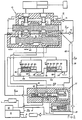
- Fig. 2 like components of Figs. 1 and 2 are designated by the same numerals.
- the priority flow control valves 10, the pilot valve sections 51, the flow control sections 87 and the nonpriority valves 115 and 116, with their controllers 117 and 118, are identical in both priority systems.
- spaces 120 and 127 are connected by lines 131, 132 and 133 to line 81, which communicates with the supply chamber 22, while spaces 121 and 128 are connected by lines 134 and 135 and line 136 to the positive load sensing system of the priority control valve 10.
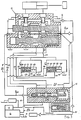
- Fig. 3 like components of Figs. 1, 2 and 3 are designated by the same numerals.
- the priority flow control valves 10, the pilot valve sections 51, the flow control sections 87 and nonpriority valves 115 and 116, with their controllers 117 and 118, are identical in all of those priority systems. However, spaces 120 and 127 are connected by lines 137, 138 and 139 to discharge line 43, while spaces 121 and 128 are connected by lines 140, 141 and 142 to upstream of metering orifice 143. Line 142 is connected by line 144 to the inlet chamber 44 of the priority control valve 10.
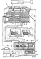
- Fig.- 4 like components of Figs. 1, 2, 3 and 4 are designated by the same numerals.
- the priority flow control valve 10, the pilot valve section 51, the flow control section 87 and the nonpriority valves 115 and 116, with their controllers 117 and 118, are identical in all of these priority systems.
- spaces 120 and 127 are connected by lines 145 and 146 with line 74, which connects annular space 61 of the pilot valve assembly 51 with control space 49 of the priority control valve 10, while spaces 121 and 128 are connected by lines 147 and 148 with the system reservoir 15.
- valve spool 18 the preferable sequencing of lands and slots of valve spool 18 is such, that when displaced in either direction from its neutral position, as shown in the drawing, one of the load chambers 23 or 24 is connected by signal slot 32 or 33 to the positive load sensing port 37 or 38, while the other load chamber is simultaneously connected by signal slot 31 or 34 with negative load sensing port 35 or 36, the load chamber 23 or 24 still being isolated from the supply chamber 22 and outlet chambers 25 and 26. Further displacement of valve spool 18 from its neutral position connects load chamber 23 or 24 through metering slot 28 or 29 with the supply chamber 22, while simultaneously connecting the other load chamber through metering slot 27 or 30 with outlet chamber 25 or 26.
- the pump flow control 14 in a well known manner, will regulate fluid flow, delivered from pump 12, to discharge line 43, to maintain the pressure in discharge line 43 higher, by a constant pressure differential, than the highest load pressure signal transmitted through the check valve system to signal line 86. Therefore, with the valve spool 18, of priority flow control valve 10, in its neutral position blocking positive load sensing ports 37 and 38, signal pressure input to pump flow control 14 from signal line 86 will be at minimum pressure level, corresponding with the minimum standby pressure of the pump 12. The control pressure differential APp of the pump flow control will be maintained at its constant predetermined level as long as the maximum flow output of the pump is not reached. Once this condition is reached the control pressure differential will reduce.
- the priority flow control valve 10 is interposed between a schematically shown pump 12 and the fluid motor 11.
- the pilot valve assembly 51 regulates the position of the control spool 40 to control the pressure differential APyp developed across orifices created by displacement of metering slots 28 and 29 and to control the pressure differential APyn, across orifices created by displacement of metering slots 27 and 30.
- Control space 66 of the pilot valve assembly 51 is connected to the system reservoir 15 by the flow control, generally designated as 87, which is a constant flow device, passing a constant flow of fluid from control space 66 to the reservoir 15, irrespective of the magnitude of control pressure P 2 , in a manner as will be described later in the text.
- valve spool 18 is displaced by the manual lever 106 from left to right by sufficient amount to connect with signal slot 33 the load chamber 23 with positive load sensing port 37, while the load chamber 23 is still isolated from the supply chamber 22.
- the load chamber 23 is subjected to a positive load pressure Pwp.
- the load pressure Pwp transmitted to passage 72 will open the check valve 70, close the check valve 71 and will be transmitted through line 69a to the controller 66a.
- the pressure drop ⁇ Px becomes negligible.
- the load pressure Pwp will be then directly transmitted to control space 66 with P 2 becoming Pwp pressure.
- Control space 66 is connected through the flow control section 87 with the system reservoir 15.
- the flow control spool 93 will automatically assume a throttling position, throttling the fluid from control space 66 at Pwp pressure, by action of throttling slots 101, to a pressure, equivalent to the preload of spring 96. Therefore space 95 will be always maintained at a constant pressure as dictated by the preload in the spring 96. Space 95 is connected through passage 103, leakage orifice 102 and passage 104 with space 94, connected to system reservoir 15 by line 105. Therefore, with constant pressure differential automatically maintained across leakage orifice 102, a constant flow, at a certain preselected minimum level, will take place from space 95 and control space 66, irrespective of the level of Pwp or P 2 pressure.
- P 2 pressure will always equal Pwp pressure.
- the pilot valve spool 54 is subjected to Pwp pressure in the control space 66, preload of the pilot valve spring 68 and pressure P 1 p in annular space 64, which is connected by line 81 to the supply chamber 22, which in turn is connected, through throttling slots 45, with the inlet chamber 44, connected by discharge line 43 to the pump 12. Under the action of those forces the pilot spool 54 will move into a modulating position, as shown in Fig.
- valve spool 18 is further displaced by the manual lever 106 from left to right, creating a metering orifice of specific area between the supply chamber 22 and the load chamber 23 through metering slot 29.
- load chamber 23 is subjected to a positive load pressure Pwp.
- Fluid flow will take place from the supply chamber 22, through created metering orifice, to the fluid motor 11, the pilot valve assembly automatically throttling, through the position of the control spool 40, the fluid flow from the inlet chamber 44 to the supply chamber 22, to maintain across created metering orifice a constant pressure differential of APyp equal to AP, which in turn is equal to the quotient of the preload of the pilot valve spring 68 and the cross-sectional area of the pilot valve spool 54. Since a constant pressure differential is maintained across created metering orifice a constant flow of fluid will be supplied to fluid motor 11, irrespective of the variation in the magnitude of the load W. Therefore under those conditions the flow to the fluid motor 11 becomes directly proportional to the flow area of the created metering orifice and independent of Pwp pressure.
- ⁇ Px any value of ⁇ Px, as can be seen from the basic equation, will automatically lower, by the same amount, APyp, acting across created metering orifice, automatically reducing the quantity of fluid flowto the fluid motor 11, this flow still being maintained constant at a constant level and independent of the variation in the magnitude of load W. Therefore, by controlling the value of ⁇ Px, by the action of controller 66a, the pressure differential ⁇ Pyp is controlled, controlling the velocity of load W. In a similar way the velocity of the load W and therefore the flow into the fluid motor 11 can be controlled by the variation in the area of the orifice created by displacement of the valve spool 18, at any controlled level of APyp, as dictated by the value of A Px.
- valve spool 18 is displaced by the manual lever 106 from left to right by a sufficient amount to connect with signal slot 31 the load chamber 24 with negative load sensing port 35, while the load chamber 24 is still isolated from the outlet chamber 25.
- the load chamber 24 is subjected to a negative load pressure Pwn.
- the pressure signal at Pwn pressure will be transmitted through passage 83 and line 82 to annular space 63 and react on the cross-sectional area of the free floating piston 55.
- no pressure signal is transmitted through line 69 and that control space 66 is subjected to reservoir pressure, by the action of the flow control section 87.
- the pilot valve spool 54 will be displaced by the free floating piston 55 all the way to the right, connecting annular space 61 and the control space 49 with annular space 59, subjected to pump discharge pressure through line 76.
- the control spool 40 will automatically move all the way from right to left, with the throttling edges 41 cutting off communication between the exhaust chamber 42 and the outlet chamber 26 and therefore isolating outlet chambers 25 and 26 from the system reservoir 15.
- valve spool 18 is further displaced by the manual lever 106 from left to right, creating a metering orifice of specific area between the load chamber 24 and the outlet chamber 25, subjected to negative load pressure Pwn.
- the negative load pressure will be automatically transmitted through line 73, will open the check valve 71, close the check valve 70 and will be transmitted through line 69 to the control space 66.
- the P 1 pressure in control space 66 will react on the cross-sectional area of pilot valve spool 54, the pilot valve spring 68 bringing it into its modulating position, as shown in the drawing and controlling the pressure in the control space 49, to establish a throttling position of the control spool 40, which will maintain a constant pressure differential across created metering orifice, as dictated by the preload of the pilot valve spring 68.
- Pwn-P 2 will equal constant ⁇ P, which is equal to the quotient of the preload of the pilot valve spring 68 and the cross-sectional area of the pilot spool 54.
- the flow control valves 10, 115 and 116 are controlling positive loads, that the ⁇ Px of the controller 66a is very small and that the flow control valve 10 is the priority flow control valve of the system, which is also using the nonpriority compensated valves 115 and 116.
- the nonpriority valves 115 and 116 are, in all aspects, identical to the priority valve assembly 10 and include the pilot valve sections 51 and the flow control sections 87.
- the controller sections 66a, 117 and 118 act in a similar way, modifying the positive load pressure signal on its way to the pilot valve assembly and therefore, in a manner as previously described, by controlling ⁇ Px control the basic control pressure differential APy.
- controller 66a there is however one difference between the controller 66a and the controllers 117 and 118. While at rest, biased by the spring 112, the piston 108 actuates the variable metering orifice section 106 towards its maximum orifice position.
- the pump 12 provided with a load responsive flow control 14, in a well known manner, will maintain a constant pressure differential APp, which is determined by a constant difference between pump discharge pressure and maximum positive load system pressure.
- the pressure differential ⁇ Pp is normally selected higher than AP, which is the constant pressure differential of the compensator of the flow control valve.
- This pressure differential APp is applied across the pistons 119 and 126, of the controls 117 and 118.
- the spring characteristics of the springs 122 and 129 are so selected, that when subjected to the force developed, due to pressure differential APp, acting on the cross-sectional area of the pistons 119 and 126, those pistons are moved all the way from left to right, providing maximum area of signal orifice and minimum value of APx.
- the performance of the priority flow control system of Fig. 1 represents a new type of priority control with many unusual and beneficial characteristics.
- a conventional priority system can only operate in a series type system, with fluid flow being subjected to the throttling action, on its way to the downstream nonpriority valves.
- the priority feature is obtained in a parallel circuit.
- the priority valve In conventional priority circuits the priority valve is provided with a priority bypass throttling section and therefore is substantially different from the nonpriority valves.
- the priority and nonpriority valves of the system are identical.
- the maximum flow of the priority valve is fixed at a certain predetermined level.
- maximum flow through the priority valve can be adjusted to any desired level.
- the priority valve during control of negative load, may absorb full flow of the pump.
- the priority valve during control of negative load, the priority valve automatically loses its priority feature. Then, as soon as the maximum pump flow output is reached, all of the other nonpriority valves automatically progressively reduce their pressure differential and therefore their flow output, the loss of proportionality of any one of those valves being completely impossible.
- Fig. 2 the basic components of the priority system are identical to that of Fig. 1, with the exception of the absence of the positive load signal throttling controller 66a, in the interral control circuit of the priority valve.
- the controllers 117 and 118 are made responsive not to ⁇ Pp of the pump, but to pressure differential AP of the priority valve. This pressure differential will automatically fully actuate the controllers 117 and 118 and maintain them in position of minimum ⁇ Px and maximum APy approaching the value of AP.
- the pressure differential AP of the priority valve will decrease, automatically progressively decreasing the pressure differential of all of the nonpriority valves.
- the final effect is the same as that, described when referring to Fig. 1, the system of Fig. 2 providing all of the same advantages.
- Fig. 3 the components of the priority flow control system of Fig. 3 are identical to those of Fig. 2, with the controllers 117 and 118, of the nonpriority valves, being made responsive to the pressure differential ⁇ P 1 , across control orifice 143.
- controllers 117 and 118 of Fig. 3 There is one basic difference between the controllers 117 and 118 of Fig. 3, as compared to those of Fig. 2.
- the pressure differential ⁇ Px With the pistons 119 and 126 in a fully extended position, the pressure differential ⁇ Px is at its minimum value, with the control pressure differential APy approaching the value of AP.
- the pressure differential ⁇ P 1 developed across the control orifice increases with flow and reaches its maximum value at maximum pump output.
- the preload in the springs 122 and 129 is so selected, that the pressure differential ⁇ P 1 , before the maximum flow output of the pump is reached, will automatically start reducing the pressure differential of the nonpriority valves 115 and 116, with the system working in an identical manner and providing identical advantages, as the systems described when referring to Figs. 1 and 2.
- Fig. 4 the basic components of the priority system are the same as those of Fig. 2 and perform in an identical way, with the controllers 117 and 118 in Fig. 4 being directly responsive to the pressure Px in control space 49.
- the pressure in the control space 49 equivalent to preload of the control spring 48, is so selected, that it will move the pistons 119 and 126 all the way from left to right into the position, equivalent
- the throttling control of the priority valve responds to its own pressure differential, trying to maintain it constant by varying the quantity of the bypass flow to the nonpriority valves, located downstream.
- the priority controls can respond to a number of different types of control signals, while providing identical performance. Examples of priority controls, using different control signals, are shown in Figs. 1 to 4. The great flexibility of the priority system and the possibility of selection of different control signals, in operation of the priority controls, permits easy integration of the priority valves into the total hydraulic system. Four representative types of control signals, used in priority controls, are shown in Figs. 1 to 4. As will be apparent to those skilled in the art, other types of control signals could be used.
- the gradual increase in ⁇ Px of the nonpriority -valve and therefore gradual increase in APy can be made responsive to the position of the displacement changing mechanism of the pump, or position of the bypass spool of the bypass valve, controlling the output of the pump, or pump RPM, if the pump is of a fixed displacement type etc.
Landscapes
- Engineering & Computer Science (AREA)
- Physics & Mathematics (AREA)
- Fluid Mechanics (AREA)
- Mechanical Engineering (AREA)
- General Engineering & Computer Science (AREA)
- Fluid-Pressure Circuits (AREA)
Description
- This invention relates generally to fluid control valves provided with positive and negative load compensation.
- In more particular aspects this invention relates to pressure compensated direction and flow control valves, the positive and negative load compensators of which are controlled by a single amplifying pilot valve stage.
- In still more particular aspects this invention relates to pilot operated pressure compensated controls of direction control valves, used in control of positive and negative load, which permit variation in the level of control differential across metering orifices of the valve spool, while this control differential is automatically maintained constant at each controlled level.
- In still more particular aspects this invention relates to pilot operated pressure compensated controls of direction control valves, which provide a priority feature for specific valves by controlling the pressure differential of all of the nonpriority valves.
- Closed center fluid control valves, pressure compensated for control of positive and negative loads, are desirable for a number of reasons. They permit load control with reduced power losses and therefore, increased system efficiency. They also permit simultaneous proportional control of multiple positive and negative loads. Such fluid control valves are shown in US-A-4180098 and also in US-A-4222409. However, the valves of those patents although capable of proportional control of positive and negative loads, use for such control the energy directly transmitted through the load pressure sensing ports, which not only attenuate the control signals, but limit the response of the control. Those valves also automatically maintain a constant pressure differential across metering orifices in control of both positive and negative loads. In those valves the priority feature is obtained by throttling the fluid flow to the downstream valves, so that the priority valve is always assured of the required flow, once the maximum flow output of the system pump is reached. Also in those valves the construction of the priority valve is substantially different from the nonpriority valves and the priority valve must work in a series type circuit.
- US-A-4231396 discloses a closed centre load responsive fluid control valve assembly supplied with pressurized fluid, the valve assembly having control orifice means interposed between the fluid supply chamber and the load chamber, and first fluid flow control means to maintain a pressure differential across the control orifice means.
- It is a principal object of this invention to provide a priority flow control system, in which the proportionality of flow of nonpriority valves is not lost, while the fluid flow is being diverted to the priority valve, once the system pump reaches its maximum flow output.
- Another object of this invention is to provide a priority flow control system, in which the pressure differential of the nonpriority valves is progressively lowered once the system pump reaches its maximum flow output, automatically providing the priority valve with the required flow.
- It is a further object of this invention to provide a priority flow control system based entirely on the principle of the parallel flow circuit.
- It is a further object of this invention to provide a priority feature to a specific valve with a minimum amount of fluid throttling, thus increasing system efficiency.
- It is a further object of this invention to provide a priority flow control system, in which the priority and nonpriority compensated control valves work in parallel circuit.
- It is a further object of this invention to provide a priority flow control system, in which the priority and nonpriority compensated flow control valves are essentially of the same construction. -
- It is a further object of this invention to provide a priority flow control system, in which the non- priority valves can be controlled by a number of different control inputs, in providing the priority feature.
- It is a further object of this invention to provide a system, in which the pressure differential and therefore maximum flow limit of all of the system valves is automatically progressively lowered, once the maximum capacity of the system pump is reached, so that none of the system valves ever lose the compensated proportional flow feature.
- According to the present invention, therefore, there is provided a priority flow control system supplied from a source of pressure fluid and connected to exhaust means, the priority flow control system including a priority valve assembly operable to control a load and at least one other her non-priority valve assembly operable to control a further load, each valve assembly having a housing connected to a fluid motor, control orifice means in the housing interposed between the source of pressure fluid and the fluid motor, fluid flow control means in the housing, first control means operable through the fluid flow control means to maintain a pressure differential across the control orifice means at a controlled constant level; characterized by second control means of the non-priority valve assembly having first means responsive to maximum fluid flow from the source of pressure fluid and second means operable through the fluid flow control means and the first control means to vary the level of the constant pressure differential so that the level of the constant pressure differential is progressively lowered by the second means once fluid flow from the source of pressure fluid reaches its maximum flow output and flow demand of the flow control system exceeds the maximum flow output.
- Examples of systems according to the invention will now be described with reference to the accompanying drawings, in which:
- Fig. 1 is a sectional view of an embodiment of a priority flow control valve, with schematically shown nonpriority system valves, responsive to the pressure differential of the system pump;
- Fig. 2 is a sectional view of an embodiment of a priority flow control valve, with schematically shown nonpriority system valves, responsive to the pressure differential of the priority valve;
- Fig. 3 is a sectional view of an embodiment of a priority flow control valve, with schematically shown nonpriority system valves, responsive to pressure differential across an orifice, subjected to full flow of the system pump;
- Fig. 4 is a sectional view of an embodiment of a priority flow control valve, with schematically shown nonpriority system valves, responsive to control pressure of the throttling controller of the priority valve.
- Referring now to Fig. 1, an embodiment of a priority flow control valve, generally designated as 10, is shown interposed between diagrammatically shown
fluid motor 11, driving load W and apump 12 of a fixed displacement or variable displacement type, driven by a prime mover, not shown. Fluid flow from thepump 12 to priorityflow control valve 10 and a circuit of diagrammatically shownflow control valve 13 is regulated bypump flow control 14. Ifpump 12 is of a fixed displacement type,pump flow control 14 is a differential pressure relief valve, which, in a well known manner, by bypassing fluid frompump 12 to areservoir 15, maintains discharge pressure ofpump 12 at a level, higher by a constant pressure differential, than load pressure developed influid motor 11. Ifpump 12 is of a variable displacement type,pump flow control 14 is a differential pressure compensator, well known in the art, which by changing displacement ofpump 12, maintains discharge pressure ofpump 12 at a level, higher by a constant pressure differential, than load pressure developed influid motor 11. - The
pump flow control 14 may also be a maximum pressure compensator or relief valve, which maintains the discharge pressure of thepump 12 at a maximum constant pressure level during operation of the system. - The priority
flow control valve 10 is of a four way type and has ahousing 16 provided with abore 17, axially guiding avalve spool 18. Thevalve spool 18 is equipped withlands 19, 20 and 21, which in neutral position of thevalve spool 18, as shown in the drawing, isolate afluid supply chamber 22,load chambers 23 and 24 andoutlet chambers Lands 19, 20 and 21, ofvalve spool 18, are provided withmetering slots signal slots 31, 32, 33 and 34. Negativeload sensing ports 35 and 36 are positioned betweenload chambers 23 and 24 andoutlet chambers load sensing ports 37 and 38 are located betweensupply chamber 22 andload chambers 23 and 24. - Negative load throttling slots 39, of
control spool 40, equipped withthrottling edges 41, connectoutlet chambers exhaust chamber 42, which in turn is connected toreservoir 15. - The
pump 12, through itsdischarge line 43, is connected to aninlet chamber 44. Theinlet chamber 44 is connected through positiveload throttling slots 45, oncontrol spool 40, provided withthrottling edges 46, with thefluid supply chamber 22. Bore 47 axially guides thecontrol spool 40, which is biased bycontrol spring 48, contained incontrol space 49, towards position as shown. The control spool 40 at one end projects intocontrol space 49, the .other end projecting intochamber 50, connected to thereservoir 15. A pilot valve assembly, generally designated as 51, comprises ahousing 52, provided with abore 53, slidably guiding apilot valve spool 54 and a freefloating piston 55. Thepilot valve spool 54 is provided withlands annular spaces housing 52 and communicates directly withbore 53. The freefloating piston 55 is provided with aland 62, which definesannular spaces extension 65 selectively engageable withland 58 of thepilot valve spool 54. The pilot valve spool 54 at one end projects intocontrol space 66 and engages, with itsland 56 andspring retainer 67, a pilot valve spring 68.Control space 66 communicates throughlines 69 and 69b and a controller, generally designated as 66a, and throughline 69a withcheck valve 70 and throughline 69 withcheck valve 71. Thecheck valve 70 is connected bypassage 72 with positiveload sensing ports 37 and 38. Thecheck valve 71 communicates throughline 73 with theoutlet chamber 25. Annular space 61, of thepilot valve assembly 51, communicates throughline 74 withcontrol space 49 and also communicates, throughleakage orifice 75, withannular space 60, which in turn is connected toreservoir 15.Annular space 59 communicates throughline 76 withdischarge line 43.Annular space 64 is connected byline 81 with thesupply chamber 22.Annular space 63 is connected byline 82 andpassage 83 with negativeload sensing ports 36 and 35. Positiveload sensing ports 37 and 38 are connected throughpassage 72,line 84 and acheck valve 85 and asignal line 86 with thepump flow control 14.Control space 66 is connected through a flow control, generally designated as 87, with thereservoir 15.Flow control 87 is a flow control device, passing a constant flow fromcontrol space 66 to thereservoir 15. Theload chambers 23 and 24 are connected, for one way fluid flow, bycheck valves control space 66 and thesystem reservoir 15 and comprises ahousing 91, provided with abore 92, guiding a flow control spool 93, which definesspaces 94 and 95 and which is biased by aspring 96. The flow control spool 93 is provided withlands annular space 99, which is connected byline 100 withcontrol space 66. The flow control spool 93 is also provided withthrottling slots 101 andleakage orifice 102, which communicates throughpassages space 95 with space 94, space 94 being connected byline 105 withsystem reservoir 15. - The controller, generally designated as 66a, is interposed between
control space 66 andcheck valve 70, communicating with positiveload sensing ports 37 and 38 and comprises schematically shownvariable orifice section 106, operated by anactuating section 107. The actuatingsection 107 is provided with apiston 108, guided in ahousing 109, definingspaces 110 and 111 and biased towards position as shown by aspring 112.Space 110 is subjected to an external fluidpower control signal 113, while space 111 is subjected to acontrol signal 114. - Schematically shown nonpriority cortrol valves, generally designated as 115 and 116, are identical to the priority
flow control valve 10 and are each provided with an identicalpilot valve section 51,flow control section 87 andcontrollers controller 66a. - The
controller 117 is provided with apiston 119, definingspaces spring 122 and is operably connected to avariable orifice section 123.Space 120 is connected by line 124 to dischargeline 43 whilespace 121 is connected by a line 125 andlines - The
controller 118 is provided with apiston 126, definingspaces spring 129 and is operably connected to avariable orifice section 130.Space 127 is connected byline 131 to dischargeline 43, whilespace 128 is connected by aline 132 andlines - Referring now to Fig. 2, like components of Figs. 1 and 2 are designated by the same numerals. The priority
flow control valves 10, thepilot valve sections 51, theflow control sections 87 and thenonpriority valves controllers spaces lines line 81, which communicates with thesupply chamber 22, whilespaces lines 134 and 135 andline 136 to the positive load sensing system of thepriority control valve 10. - Referring now to Fig. 3, like components of Figs. 1, 2 and 3 are designated by the same numerals. The priority
flow control valves 10, thepilot valve sections 51, theflow control sections 87 andnonpriority valves controllers spaces lines line 43, whilespaces lines metering orifice 143.Line 142 is connected byline 144 to theinlet chamber 44 of thepriority control valve 10. - Referring now to Fig.- 4, like components of Figs. 1, 2, 3 and 4 are designated by the same numerals. The priority
flow control valve 10, thepilot valve section 51, theflow control section 87 and thenonpriority valves controllers spaces lines line 74, which connects annular space 61 of thepilot valve assembly 51 withcontrol space 49 of thepriority control valve 10, whilespaces lines system reservoir 15. - Referring back now to Fig. 1, the preferable sequencing of lands and slots of
valve spool 18 is such, that when displaced in either direction from its neutral position, as shown in the drawing, one of theload chambers 23 or 24 is connected bysignal slot 32 or 33 to the positiveload sensing port 37 or 38, while the other load chamber is simultaneously connected by signal slot 31 or 34 with negativeload sensing port 35 or 36, theload chamber 23 or 24 still being isolated from thesupply chamber 22 andoutlet chambers valve spool 18 from its neutral position connectsload chamber 23 or 24 throughmetering slot supply chamber 22, while simultaneously connecting the other load chamber throughmetering slot outlet chamber - As previously described the
pump flow control 14, in a well known manner, will regulate fluid flow, delivered frompump 12, to dischargeline 43, to maintain the pressure indischarge line 43 higher, by a constant pressure differential, than the highest load pressure signal transmitted through the check valve system to signalline 86. Therefore, with thevalve spool 18, of priorityflow control valve 10, in its neutral position blocking positiveload sensing ports 37 and 38, signal pressure input to pumpflow control 14 fromsignal line 86 will be at minimum pressure level, corresponding with the minimum standby pressure of thepump 12. The control pressure differential APp of the pump flow control will be maintained at its constant predetermined level as long as the maximum flow output of the pump is not reached. Once this condition is reached the control pressure differential will reduce. - As shown in Fig. 1, the priority
flow control valve 10 is interposed between a schematically shownpump 12 and thefluid motor 11. Thepilot valve assembly 51, in a manner as will be described later in the text, regulates the position of thecontrol spool 40 to control the pressure differential APyp developed across orifices created by displacement ofmetering slots metering slots Control space 66 of thepilot valve assembly 51 is connected to thesystem reservoir 15 by the flow control, generally designated as 87, which is a constant flow device, passing a constant flow of fluid fromcontrol space 66 to thereservoir 15, irrespective of the magnitude of control pressure P2, in a manner as will be described later in the text. This constant flow of fluid passes through thecontroller 66a, which is interposed between the positive load pressure sensing circuit of priorityflow control valve 10 andcontrol space 66 of thepilot valve assembly 51. In a well known manner, for each specific position of thepiston 108 and equivalent area of variable orifice of variable orifice section 106 a constant pressure differential, equal to ΔPx will be developed across thecontroller 66a. It is assumed, when describing the operation of the flow control valve of this invention, that with thepiston 108 displaced by thespring 112 all the way to the left, the pressure differential ΔPx becomes so small that the value of control pressure P2 approaches the value of Pwp pressure. - Assume that the
valve spool 18 is displaced by themanual lever 106 from left to right by sufficient amount to connect with signal slot 33 the load chamber 23 with positive load sensing port 37, while the load chamber 23 is still isolated from thesupply chamber 22. Assume also that the load chamber 23 is subjected to a positive load pressure Pwp. The load pressure Pwp transmitted topassage 72 will open thecheck valve 70, close thecheck valve 71 and will be transmitted throughline 69a to thecontroller 66a. Assume that due to full displacement to the left of thepiston 108 the pressure drop ΔPx becomes negligible. The load pressure Pwp will be then directly transmitted to controlspace 66 with P2 becoming Pwp pressure.Control space 66 is connected through theflow control section 87 with thesystem reservoir 15. In a well known manner, the flow control spool 93 will automatically assume a throttling position, throttling the fluid fromcontrol space 66 at Pwp pressure, by action of throttlingslots 101, to a pressure, equivalent to the preload ofspring 96. Thereforespace 95 will be always maintained at a constant pressure as dictated by the preload in thespring 96.Space 95 is connected throughpassage 103,leakage orifice 102 andpassage 104 with space 94, connected tosystem reservoir 15 byline 105. Therefore, with constant pressure differential automatically maintained acrossleakage orifice 102, a constant flow, at a certain preselected minimum level, will take place fromspace 95 andcontrol space 66, irrespective of the level of Pwp or P2 pressure. With thecontroller 66a in a fully open position, equivalent to minimum resistance to flow, P2 pressure will always equal Pwp pressure. Thepilot valve spool 54 is subjected to Pwp pressure in thecontrol space 66, preload of the pilot valve spring 68 and pressure P1p inannular space 64, which is connected byline 81 to thesupply chamber 22, which in turn is connected, through throttlingslots 45, with theinlet chamber 44, connected bydischarge line 43 to thepump 12. Under the action of those forces thepilot spool 54 will move into a modulating position, as shown in Fig. 1, regulating the pressure in thecontrol space 49 and therefore position of thecontrol spool 40, throttling by throttlingedges 46 the fluid flow from theinlet chamber 44 to thesupply chamber 22, to maintain a constant pressure differential betweenannular space 64 andcontrol space 66, equivalent to preload of the pilot valve spring 68. The free floatingpiston 55, subjected to pressure differential betweenannular spaces pilot spool 54. Since thesupply chamber 22 is closed by position of thevalve spool 18 from the load chamber 23 thecontrol spool 40 will assume a position, in which throttling edges 46 will completely isolate theinlet chamber 44 from thesupply chamber 22. - Assume that the
valve spool 18 is further displaced by themanual lever 106 from left to right, creating a metering orifice of specific area between thesupply chamber 22 and the load chamber 23 throughmetering slot 29. Assume also that the load chamber 23 is subjected to a positive load pressure Pwp. Fluid flow will take place from thesupply chamber 22, through created metering orifice, to thefluid motor 11, the pilot valve assembly automatically throttling, through the position of thecontrol spool 40, the fluid flow from theinlet chamber 44 to thesupply chamber 22, to maintain across created metering orifice a constant pressure differential of APyp equal to AP, which in turn is equal to the quotient of the preload of the pilot valve spring 68 and the cross-sectional area of thepilot valve spool 54. Since a constant pressure differential is maintained across created metering orifice a constant flow of fluid will be supplied tofluid motor 11, irrespective of the variation in the magnitude of the load W. Therefore under those conditions the flow to thefluid motor 11 becomes directly proportional to the flow area of the created metering orifice and independent of Pwp pressure. - Assume that while controlling a positive load W, in a manner as described above, the
piston 108 of thecontroller 66a was moved back into an intermediate position, creating a resistance to constant flow, by reduction in flow area of metering orifice. Assume also that due to that resistance a pressure differential ΔPx is developed across the variablemetering orifice section 106 of thecontroller 66a. Then thecontrol space 66 will be subjected to P2 pressure which is equal to the difference between Pwp pressure and ΔPx. It can be seen that APyp = P1p-Pwp, which is the pressure differential through created metering orifice, P1p-P2 = ΔP, which is the constant pressure differential caused by the preload of the pilot valve spring 68 and that PWP-P2 = APx. From the above three equations, when substituting and eliminating P1p, Pwp and P2 pressures, the basic relationship of APyp = ΔP-ΔPx is obtained. With ΔPx = 0 which is the case, as explained above, when thecontroller 66a is in its fully open position, APyp = AP and the flow through the created metering orifice to the fluid motor is controlled at maximum constant pressure differential. Any value of ΔPx, as can be seen from the basic equation, will automatically lower, by the same amount, APyp, acting across created metering orifice, automatically reducing the quantity of fluid flowto thefluid motor 11, this flow still being maintained constant at a constant level and independent of the variation in the magnitude of load W. Therefore, by controlling the value of ΔPx, by the action ofcontroller 66a, the pressure differential ΔPyp is controlled, controlling the velocity of load W. In a similar way the velocity of the load W and therefore the flow into thefluid motor 11 can be controlled by the variation in the area of the orifice created by displacement of thevalve spool 18, at any controlled level of APyp, as dictated by the value of A Px. - Assume that the
valve spool 18 is displaced by themanual lever 106 from left to right by a sufficient amount to connect with signal slot 31 theload chamber 24 with negative load sensing port 35, while theload chamber 24 is still isolated from theoutlet chamber 25. Assume also that theload chamber 24 is subjected to a negative load pressure Pwn. Then the pressure signal at Pwn pressure will be transmitted throughpassage 83 andline 82 toannular space 63 and react on the cross-sectional area of the free floatingpiston 55. Assume also that with communication between theload chamber 24 and theoutlet chamber 25 closed no pressure signal is transmitted throughline 69 and thatcontrol space 66 is subjected to reservoir pressure, by the action of theflow control section 87. Thepilot valve spool 54 will be displaced by the free floatingpiston 55 all the way to the right, connecting annular space 61 and thecontrol space 49 withannular space 59, subjected to pump discharge pressure throughline 76. Thecontrol spool 40 will automatically move all the way from right to left, with the throttling edges 41 cutting off communication between theexhaust chamber 42 and theoutlet chamber 26 and therefore isolatingoutlet chambers system reservoir 15. - Assume that the
valve spool 18 is further displaced by themanual lever 106 from left to right, creating a metering orifice of specific area between theload chamber 24 and theoutlet chamber 25, subjected to negative load pressure Pwn. With thecontrol spool 40 blocking theoutlet chamber 26 from theexhaust chamber 42, the negative load pressure will be automatically transmitted throughline 73, will open thecheck valve 71, close thecheck valve 70 and will be transmitted throughline 69 to thecontrol space 66. The P1 pressure incontrol space 66 will react on the cross-sectional area ofpilot valve spool 54, the pilot valve spring 68 bringing it into its modulating position, as shown in the drawing and controlling the pressure in thecontrol space 49, to establish a throttling position of thecontrol spool 40, which will maintain a constant pressure differential across created metering orifice, as dictated by the preload of the pilot valve spring 68. Then Pwn-P2 will equal constant ΔP, which is equal to the quotient of the preload of the pilot valve spring 68 and the cross-sectional area of thepilot spool 54. Since a constant pressure differential of APyn = AP is maintained across the created metering orifice, flow out of thefluid motor 11 will be proportional to the area of the created metering orifice and independent of the magnitude of the negative load W. Therefore in this way, by varying the flow area of the metering orifice created by displacement of thevalve spool 18, the velocity of the negative load W can be controlled, each area of orifice representing a specific constant flow level, independent of the magnitude of the load W. - During control of positive load the free floating
piston 55 is forceably maintained by a pressure differential out of contact with thepilot valve spool 54. During control of negative load the free floatingpiston 55 acts together with thepilot spool 54. During control of positive load the pressure differential across the orifice created by displacement of thevalve spool 18, is controlled by the throttling action of positiveload throttling slots 45. During control of negative load the pressure differential across the orifice created by displacement of thevalve spool 18, is maintained by the throttling action of the negative load throttling slots 39: During control of positive loads pressure differential, acting across created metering orifice can be varied by thecontroller 66a. - Assume that the
flow control valves controller 66a is very small and that theflow control valve 10 is the priority flow control valve of the system, which is also using the nonpriority compensatedvalves nonpriority valves priority valve assembly 10 and include thepilot valve sections 51 and theflow control sections 87. Thecontroller sections controller 66a and thecontrollers spring 112, thepiston 108 actuates the variablemetering orifice section 106 towards its maximum orifice position. Thecontrollers springs metering orifice sections pistons - The
pump 12, provided with a loadresponsive flow control 14, in a well known manner, will maintain a constant pressure differential APp, which is determined by a constant difference between pump discharge pressure and maximum positive load system pressure. The pressure differential ΔPp is normally selected higher than AP, which is the constant pressure differential of the compensator of the flow control valve. This pressure differential APp is applied across thepistons controls springs pistons controllers flow control valves - The performance of the priority flow control system of Fig. 1 represents a new type of priority control with many unusual and beneficial characteristics. A conventional priority system can only operate in a series type system, with fluid flow being subjected to the throttling action, on its way to the downstream nonpriority valves. In the system of the present invention the priority feature is obtained in a parallel circuit.
- In conventional priority circuits, once the capacity of the pump is exceeded and the priority section starts throttling, all of the other nonpriority valves may lose their proportionality feature. In the present invention, while priority flow is being directed to the priority valve, all of the other nonpriority valves fully retain their proportionality feature.
- In conventional priority circuits large throttling loss takes place in the priority valve section. In the present invention by gradually reducing the pressure differential of the nonpriority valves, none of those large throttling losses take place, with the system working at high efficiency level.
- In conventional priority circuits the priority valve is provided with a priority bypass throttling section and therefore is substantially different from the nonpriority valves. In the present invention the priority and nonpriority valves of the system are identical.
- In conventional priority circuits the maximum flow of the priority valve is fixed at a certain predetermined level. In the control system of the present invention, by varying the control pressure differential, maximum flow through the priority valve can be adjusted to any desired level.
- In conventional priority systems the priority valve, during control of negative load, may absorb full flow of the pump. In the system of the present invention, during control of negative load, the priority valve automatically loses its priority feature. Then, as soon as the maximum pump flow output is reached, all of the other nonpriority valves automatically progressively reduce their pressure differential and therefore their flow output, the loss of proportionality of any one of those valves being completely impossible.
- Referring now to Fig. 2, the basic components of the priority system are identical to that of Fig. 1, with the exception of the absence of the positive load
signal throttling controller 66a, in the interral control circuit of the priority valve. Thecontrollers controllers pump 12 will reach its maximum flow output, the pressure differential AP of the priority valve will decrease, automatically progressively decreasing the pressure differential of all of the nonpriority valves. The final effect is the same as that, described when referring to Fig. 1, the system of Fig. 2 providing all of the same advantages. - Referring now to Fig. 3, the components of the priority flow control system of Fig. 3 are identical to those of Fig. 2, with the
controllers control orifice 143. There is one basic difference between thecontrollers pistons springs nonpriority valves - Referring now to Fig. 4, the basic components of the priority system are the same as those of Fig. 2 and perform in an identical way, with the
controllers control space 49. The pressure in thecontrol space 49, equivalent to preload of thecontrol spring 48, is so selected, that it will move thepistons - to minimum APx and maximum APy, which approaches the value of AP. This can be accomplished, since the
spaces control space 49 exceeds the preload of thecontrol spring 48, thepriority valve 10 is throttling the fluid flow to the positive load and therefore is receiving the required flow. Drop in the control pressure Px incontrol space 49, below this critical level, with thevalve spool 40 in the position as shown in Fig. 4, signifying that the system pump has reached its maximum flow output, will progressively reduce the pressure differential of the nonpriorityvalves, automatically increasing the flow into the priority circuit. The basic operation of the system of Fig. 4 and its advantages are identical to those of the systems of Figs. 1, 2 and 3. - A number of advantages of the priority system of this invention, over a conventional priority system, were previously described, when referring to Fig. I. There is another basic advantage of the present invention.
- In a conventional priority series type system the throttling control of the priority valve responds to its own pressure differential, trying to maintain it constant by varying the quantity of the bypass flow to the nonpriority valves, located downstream. In the priority system of the present invention the priority controls can respond to a number of different types of control signals, while providing identical performance. Examples of priority controls, using different control signals, are shown in Figs. 1 to 4. The great flexibility of the priority system and the possibility of selection of different control signals, in operation of the priority controls, permits easy integration of the priority valves into the total hydraulic system. Four representative types of control signals, used in priority controls, are shown in Figs. 1 to 4. As will be apparent to those skilled in the art, other types of control signals could be used. For example the gradual increase in ΔPx of the nonpriority -valve and therefore gradual increase in APy can be made responsive to the position of the displacement changing mechanism of the pump, or position of the bypass spool of the bypass valve, controlling the output of the pump, or pump RPM, if the pump is of a fixed displacement type etc.
Claims (11)
Applications Claiming Priority (2)
| Application Number | Priority Date | Filing Date | Title |
|---|---|---|---|
| US357035 | 1982-03-11 | ||
| US06/357,035 US4437307A (en) | 1982-03-11 | 1982-03-11 | Priority flow control system |
Publications (3)
| Publication Number | Publication Date |
|---|---|
| EP0102959A1 EP0102959A1 (en) | 1984-03-21 |
| EP0102959A4 EP0102959A4 (en) | 1986-02-20 |
| EP0102959B1 true EP0102959B1 (en) | 1989-02-01 |
Family
ID=23404032
Family Applications (1)
| Application Number | Title | Priority Date | Filing Date |
|---|---|---|---|
| EP83900400A Expired EP0102959B1 (en) | 1982-03-11 | 1982-12-23 | Priority flow control system |
Country Status (6)
| Country | Link |
|---|---|
| US (1) | US4437307A (en) |
| EP (1) | EP0102959B1 (en) |
| JP (1) | JPS59500327A (en) |
| CA (1) | CA1193156A (en) |
| DE (1) | DE3279420D1 (en) |
| WO (1) | WO1983003286A1 (en) |
Families Citing this family (11)
| Publication number | Priority date | Publication date | Assignee | Title |
|---|---|---|---|---|
| US4515181A (en) * | 1983-05-25 | 1985-05-07 | Caterpillar Tractor Co. | Flow control valve assembly wth quick response |
| US4884942A (en) * | 1986-06-30 | 1989-12-05 | Atlas Copco Aktiebolag | Thrust monitoring and balancing apparatus |
| WO1992015799A1 (en) * | 1991-03-07 | 1992-09-17 | Caterpillar Inc. | Negative load control and energy utilizing system |
| US5379585A (en) * | 1993-07-06 | 1995-01-10 | General Electric Company | Hydraulic control system for a jet engine nozzle |
| US5873244A (en) * | 1997-11-21 | 1999-02-23 | Caterpillar Inc. | Positive flow control system |
| US5950429A (en) * | 1997-12-17 | 1999-09-14 | Husco International, Inc. | Hydraulic control valve system with load sensing priority |
| US6321152B1 (en) | 1999-12-16 | 2001-11-20 | Caterpillar Inc. | System and method for inhibiting saturation of a hydraulic valve assembly |
| US7146808B2 (en) * | 2004-10-29 | 2006-12-12 | Caterpillar Inc | Hydraulic system having priority based flow control |
| WO2007132488A1 (en) * | 2006-05-15 | 2007-11-22 | Nem S.P.A. | A fluid flow distribution device and a plant for fluid flow distribution comprising the device |
| US7908853B2 (en) * | 2007-09-28 | 2011-03-22 | Caterpillar Inc. | Hydraulic balancing for steering management |
| US7748279B2 (en) | 2007-09-28 | 2010-07-06 | Caterpillar Inc | Hydraulics management for bounded implements |
Citations (3)
| Publication number | Priority date | Publication date | Assignee | Title |
|---|---|---|---|---|
| US4180098A (en) * | 1976-02-05 | 1979-12-25 | Tadeusz Budzich | Load responsive fluid control valve |
| US4222409A (en) * | 1978-10-06 | 1980-09-16 | Tadeusz Budzich | Load responsive fluid control valve |
| US4231396A (en) * | 1979-01-26 | 1980-11-04 | Tadeusz Budzich | Load responsive fluid control valves |
Family Cites Families (11)
| Publication number | Priority date | Publication date | Assignee | Title |
|---|---|---|---|---|
| FR92211E (en) * | 1964-06-15 | 1968-10-11 | Device for controlling the flow of a hydraulic fluid independently of its pressure and directional valves fitted with this device | |
| US3768372A (en) | 1972-07-13 | 1973-10-30 | Borg Warner | Control arrangement for hydraulic systems |
| US4282898A (en) | 1979-11-29 | 1981-08-11 | Caterpillar Tractor Co. | Flow metering valve with operator selectable boosted flow |
| US4330991A (en) * | 1980-01-02 | 1982-05-25 | Tadeusz Budzich | Load responsive system controls |
| US4285195A (en) * | 1980-01-02 | 1981-08-25 | Tadeusz Budzich | Load responsive control system |
| US4362088A (en) * | 1980-01-02 | 1982-12-07 | Tadeusz Budzich | Load responsive fluid control valve |
| US4327627A (en) * | 1980-01-07 | 1982-05-04 | Tadeusz Budzich | Load responsive fluid control valve |
| US4327763A (en) * | 1980-01-11 | 1982-05-04 | Tadeusz Budzich | Dual control input flow control valve |
| US4325289A (en) * | 1980-01-11 | 1982-04-20 | Tadeusz Budzich | Load responsive fluid control valve |
| US4333389A (en) * | 1980-01-18 | 1982-06-08 | Tadeusz Budzich | Load responsive fluid control valve |
| US4362087A (en) * | 1981-03-26 | 1982-12-07 | Tadeusz Budzich | Fully compensated fluid control valve |
-
1982
- 1982-03-11 US US06/357,035 patent/US4437307A/en not_active Expired - Lifetime
- 1982-12-23 DE DE8383900400T patent/DE3279420D1/en not_active Expired
- 1982-12-23 EP EP83900400A patent/EP0102959B1/en not_active Expired
- 1982-12-23 WO PCT/US1982/001792 patent/WO1983003286A1/en not_active Ceased
- 1982-12-23 JP JP83500506A patent/JPS59500327A/en active Pending
-
1983
- 1983-02-09 CA CA000421209A patent/CA1193156A/en not_active Expired
Patent Citations (3)
| Publication number | Priority date | Publication date | Assignee | Title |
|---|---|---|---|---|
| US4180098A (en) * | 1976-02-05 | 1979-12-25 | Tadeusz Budzich | Load responsive fluid control valve |
| US4222409A (en) * | 1978-10-06 | 1980-09-16 | Tadeusz Budzich | Load responsive fluid control valve |
| US4231396A (en) * | 1979-01-26 | 1980-11-04 | Tadeusz Budzich | Load responsive fluid control valves |
Also Published As
| Publication number | Publication date |
|---|---|
| EP0102959A4 (en) | 1986-02-20 |
| DE3279420D1 (en) | 1989-03-09 |
| CA1193156A (en) | 1985-09-10 |
| EP0102959A1 (en) | 1984-03-21 |
| WO1983003286A1 (en) | 1983-09-29 |
| US4437307A (en) | 1984-03-20 |
| JPS59500327A (en) | 1984-03-01 |
Similar Documents
| Publication | Publication Date | Title |
|---|---|---|
| US4107923A (en) | Load responsive valve assemblies | |
| US4222409A (en) | Load responsive fluid control valve | |
| US4082111A (en) | Load responsive fluid control valve | |
| US3984979A (en) | Load responsive fluid control valves | |
| US4180098A (en) | Load responsive fluid control valve | |
| EP0102959B1 (en) | Priority flow control system | |
| US4028889A (en) | Load responsive fluid control system | |
| US4147178A (en) | Load responsive valve assemblies | |
| US4122677A (en) | Load responsive valve assemblies | |
| US4437388A (en) | Dual input pressure compensated fluid control valve | |
| EP0075577B1 (en) | Fully compensated fluid control valve | |
| US4089346A (en) | Load responsive fluid control valves | |
| US4058139A (en) | Load responsive fluid control valves | |
| EP0113724B1 (en) | Fully compensated fluid control valve | |
| US4249570A (en) | Exhaust pressurization of load responsive system | |
| US4058140A (en) | Load responsive fluid control valves | |
| CA1056694A (en) | Load responsive fluid control valves | |
| US4436020A (en) | Dual input pressure compensated fluid control valve | |
| US4293001A (en) | Load responsive fluid control valve | |
| US4267860A (en) | Load responsive valve assemblies | |
| US4436115A (en) | Pressure compensated fluid control valve with maximum flow adjustment | |
| US4231396A (en) | Load responsive fluid control valves | |
| US4293000A (en) | Load responsive fluid control valve | |
| US4249569A (en) | Load responsive fluid control valve | |
| US4416304A (en) | Fully compensated fluid control valve |
Legal Events
| Date | Code | Title | Description |
|---|---|---|---|
| PUAI | Public reference made under article 153(3) epc to a published international application that has entered the european phase |
Free format text: ORIGINAL CODE: 0009012 |
|
| 17P | Request for examination filed |
Effective date: 19831018 |
|
| AK | Designated contracting states |
Designated state(s): DE FR GB |
|
| A4 | Supplementary search report drawn up and despatched |
Effective date: 19860220 |
|
| RIN1 | Information on inventor provided before grant (corrected) |
Inventor name: BUDZICH, TADEUSZ |
|
| 17Q | First examination report despatched |
Effective date: 19870819 |
|
| RAP1 | Party data changed (applicant data changed or rights of an application transferred) |
Owner name: CATERPILLAR INC. |
|
| GRAA | (expected) grant |
Free format text: ORIGINAL CODE: 0009210 |
|
| AK | Designated contracting states |
Kind code of ref document: B1 Designated state(s): DE FR GB |
|
| REF | Corresponds to: |
Ref document number: 3279420 Country of ref document: DE Date of ref document: 19890309 |
|
| ET | Fr: translation filed | ||
| PLBE | No opposition filed within time limit |
Free format text: ORIGINAL CODE: 0009261 |
|
| STAA | Information on the status of an ep patent application or granted ep patent |
Free format text: STATUS: NO OPPOSITION FILED WITHIN TIME LIMIT |
|
| 26N | No opposition filed | ||
| PGFP | Annual fee paid to national office [announced via postgrant information from national office to epo] |
Ref country code: FR Payment date: 19941026 Year of fee payment: 13 |
|
| PGFP | Annual fee paid to national office [announced via postgrant information from national office to epo] |
Ref country code: GB Payment date: 19941107 Year of fee payment: 13 |
|
| PG25 | Lapsed in a contracting state [announced via postgrant information from national office to epo] |
Ref country code: GB Effective date: 19951223 |
|
| GBPC | Gb: european patent ceased through non-payment of renewal fee |
Effective date: 19951223 |
|
| PG25 | Lapsed in a contracting state [announced via postgrant information from national office to epo] |
Ref country code: FR Effective date: 19960830 |
|
| PGFP | Annual fee paid to national office [announced via postgrant information from national office to epo] |
Ref country code: DE Payment date: 19961028 Year of fee payment: 15 |
|
| REG | Reference to a national code |
Ref country code: FR Ref legal event code: ST |
|
| PG25 | Lapsed in a contracting state [announced via postgrant information from national office to epo] |
Ref country code: DE Free format text: LAPSE BECAUSE OF NON-PAYMENT OF DUE FEES Effective date: 19980901 |