EP0102884A1 - Direct drive servo valve - Google Patents
Direct drive servo valve Download PDFInfo
- Publication number
- EP0102884A1 EP0102884A1 EP83401596A EP83401596A EP0102884A1 EP 0102884 A1 EP0102884 A1 EP 0102884A1 EP 83401596 A EP83401596 A EP 83401596A EP 83401596 A EP83401596 A EP 83401596A EP 0102884 A1 EP0102884 A1 EP 0102884A1
- Authority
- EP
- European Patent Office
- Prior art keywords
- sleeve
- spool
- fluid pressure
- housing
- direct drive
- Prior art date
- Legal status (The legal status is an assumption and is not a legal conclusion. Google has not performed a legal analysis and makes no representation as to the accuracy of the status listed.)
- Granted
Links
Images

Classifications
-
- F—MECHANICAL ENGINEERING; LIGHTING; HEATING; WEAPONS; BLASTING
- F15—FLUID-PRESSURE ACTUATORS; HYDRAULICS OR PNEUMATICS IN GENERAL
- F15B—SYSTEMS ACTING BY MEANS OF FLUIDS IN GENERAL; FLUID-PRESSURE ACTUATORS, e.g. SERVOMOTORS; DETAILS OF FLUID-PRESSURE SYSTEMS, NOT OTHERWISE PROVIDED FOR
- F15B13/00—Details of servomotor systems ; Valves for servomotor systems
- F15B13/02—Fluid distribution or supply devices characterised by their adaptation to the control of servomotors
- F15B13/04—Fluid distribution or supply devices characterised by their adaptation to the control of servomotors for use with a single servomotor
- F15B13/044—Fluid distribution or supply devices characterised by their adaptation to the control of servomotors for use with a single servomotor operated by electrically-controlled means, e.g. solenoids, torque-motors
-
- F—MECHANICAL ENGINEERING; LIGHTING; HEATING; WEAPONS; BLASTING
- F15—FLUID-PRESSURE ACTUATORS; HYDRAULICS OR PNEUMATICS IN GENERAL
- F15B—SYSTEMS ACTING BY MEANS OF FLUIDS IN GENERAL; FLUID-PRESSURE ACTUATORS, e.g. SERVOMOTORS; DETAILS OF FLUID-PRESSURE SYSTEMS, NOT OTHERWISE PROVIDED FOR
- F15B13/00—Details of servomotor systems ; Valves for servomotor systems
- F15B13/02—Fluid distribution or supply devices characterised by their adaptation to the control of servomotors
- F15B13/04—Fluid distribution or supply devices characterised by their adaptation to the control of servomotors for use with a single servomotor
- F15B13/0401—Valve members; Fluid interconnections therefor
- F15B13/0406—Valve members; Fluid interconnections therefor for rotary valves
Definitions
- This invention relates to a direct drive servo valve.
- a direct drive servo valve includes a housing containing conduits connecting fluid from a high pressure source to and from a hydraulic actuator and includes a sleeve in the housing including passageways connected to the various conduits and a spool member movable to interconnect the passageways as desired to control the flow of operating fluid to the actuator, with motor means being employed to drive the spool.
- the usual servo valve for controlling hydraulic actuators includes a spool valve movable linearly to direct fluid to one side or the other of an actuating piston while permitting flow from the opposite side to a return or low pressure source.
- the spool member may be movable manually or it may be controlled by means of an electrohydraulic torque motor which receives electrical control signals from a control system.
- the electrohydraulic torque motor since it includes a pair of fluid jets with a flapper member movable to open one jet and partially close the other, constantly leaks a certain amount of operating fluid and thus imposes a load on the pumping system.
- torque motor drives a spool valve which is connected to both its input signal source and its output through a series of fluid conduits.
- This usually requires that the system incorporate at least a direct mechanical position feedback means and perhaps an electrical feedback to the torque motor as well.
- the electrical motor could drive the servo valve directly to avoid such a "floating" spool valve.
- the torque motor inherently has a rotary output but the desired servo valve output is linear, the rotary motion of the torque motor armature must be converted to a linear motion, accomplished by the jet and flapper structure discussed above which varies the fluid pressure on opposite ends of the spool valve to cause it to move linearly.
- the direct drive servo valve of the invention utilizes a rotary torque motor having a limited displacement which operates through an output shaft to directly drive the spool of a rotary servo valve.
- a torque tube is sealed at one end to the output shaft and at its opposite end to either the sleeve or housing and thereby provides the dual functions of sealing operating fluid away from the motor windings and of acting as a return spring to center the output shaft and spool in the desired null position.
- the rotatable valve structure consists of a housing containing a sleeve .
- the spool member is machined to the desired diameter to fit in the center of the sleeve and includes a series of channels which are rotated by the torque motor to provide the desired interconnections among the sleeve passageways.
- One advantage resulting from the invention is that the direct drive rotary valve arrangement eliminates the necessity of converting the torque motor rotary motion to linear motion.
- the rotary arrangement facilitates pressure-balancing of the spool in that the spool can be made symmetrical with fluid pressure forces acting on opposite sides simultaneously to reduce the required operating forces.
- a further advantage of the present invention is that the torque tube is utilized not only as a seal but also as a centering spring to assure that the spool returns to null position with electrical power off.
- a further advantage is that the leakage of operating fluid referred to above is eliminated.
- a still further advantage is that the direct drive valve, although having rather complicated patterns of passageways in its sleeve structure, is amenable to production through the use of stacked disks having various patterns of cutouts made with electrical discharge milling (EDM) techniques or photo-etching techniques.
- EDM electrical discharge milling
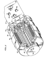
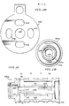
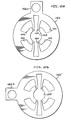
- FIG. 1 is a perspective drawing, partially in section, showing our direct drive valve assembly including the torque motor 10 which drives a spool in the mechanical housing assembly 12.
- the torque motor includes a housing 14 containing electrical windings 16, a magnet structure 18, and a rotatable armature member 20 which is supported in the housing in bearings 22 and 24.
- armature 20 At its left end armature 20 is sealed to a torque tube 26 which, in turn, is sealed to an output shaft 28.
- the opposite end of torque tube 26 is sealed to a member 30 which is pinned or otherwise secured to the housing 14.
- Member 30 may be, and preferably is, a part of the torque tube.
- housing 12 includes a plurality of ports, port 34 being connected to a source of operating fluid under high pressure (P), port 36 being connected to the return side of said source (R), port 38 being connected to supply pressure to drive an associated actuator in one direction such as to extend it (C E ) and port 40 being connected to the opposite side of said actuator to drive it in the opposite direction such as to retract it (C R ).
- port 34 being connected to a source of operating fluid under high pressure (P)
- port 36 being connected to the return side of said source (R)
- port 38 being connected to supply pressure to drive an associated actuator in one direction such as to extend it (C E )
- port 40 being connected to the opposite side of said actuator to drive it in the opposite direction such as to retract it (C R ).
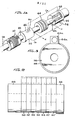
- Figure la constitutes an extension of the sectional structure of Figure 1 in that the output shaft 28 is shown connected to the flexible coupling 32 which, in turn, is connected to a spool member 42 rotatable within a sleeve 44 shown in parts in this particular schematic presentation.
- a spool member 42 rotatable within a sleeve 44 shown in parts in this particular schematic presentation.
- C R return pressure
- the spool will be in a position to open a port 52 which permits flow from the actuator (C E ) to the return port 36 (R). Again, the flow from the extend side of the actuator C E flows along the spool to a port 54 but flows no farther because this port is blocked by the spool 42. This, of course, is only one of the patterns of flow through this valve, and others will be discussed below.
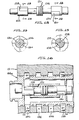
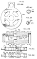
- Figures 2 and 3 depict the arrangement of parts making up a typical sleeve assembly for our direct drive valve, Figure 2 being a side view showing endcaps 56 and 58 and a plurality of stacked disk members 60, 62, 64, 66, 64, 62, and 60'.
- Figure 3 is an end view of the assembly shown in Figure 2, showing the endcap member 56 as well as a tab 60a forming part of disk 60 as will appear hereafter. Also visible in this view is tab 64a forming part of disk 64, but similar tabs aligned with 64a are behind it forming parts of disks 62 and 60' appearing near the right end of the assembly of Figure 2. The center bores of these tabs are drilled slightly off- center so as to produce this desired misalignment when the disks are assembled to indicate which disks are reversed.
- Figures 4 and 5 are plan and side views, respectively, of the end blocks of the assembly shown in Figure 2. It will be seen that these are simple annular structures with a flat at the top as shown in Figure 3.
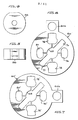
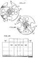
- Figure 6 is an enlarged plan view of disk 60 shown in Figure 2 which includes tab 60a at the top with a center bore located slightly off center of the tab but centered on a radius of the disk 60.
- This view of disk 60 shows a center bore 68 communicating with opposite radial passages or openings 70 and 72 and also with a plurality of openings 74, 76, 78 and 80 which are located at 0°, 90 0 , 180 0 , and 2700, respectively, with 0° being chosen as the top position.
- Openings 74 and 78 are larger than openings 76 and 80 and extend farther toward the outside of the disk.
- each of openings 74 and 78 will provide openings from the outside of the sleeve to the center of the sleeve assembly.
- Figure 7 is a disk of essentially the same configuration as Figure 6, but with one significant exception in that disk 60' includes a tab 60'a which is displaced 90° from tab 60a relative to the rest of the openings in the disk. Thus, tab 60'a is positioned at approximately 90 0 or in alignment with opening 76'.
- Figure 8 is a plan view of the two disks indicated at number 62 in Figure 2. It has a tab 62a at the top which is also slightly out of alignment with the center of the disk. This disk has a plurality of large area openings 86, 88, 90 and 92, none of which are designed to open to the outside surface when the sleeve is trimmed. When an identical copy of this disk is reversed, but with the tab still at the top, the reversed disk is aligned with disk 64a (see Figure 3). Reversing of this disk will place the elongated large area slots 82 and 84 at the 135 0 - 315 0 positions (as measured with 0° at the top) rather than at the 45 0 - 225 0 positions.
- Figure 9 is a plan view of a disk 64 which is quite similar to disk 62 except for the elongated large area slots 94 and 96 which are oriented similarly to slots 82 and 84.
- These slots which extend a greater distance toward the periphery of the disk than slots 82 and 84 include outwardly extending radii which will remain when the sleeve is trimmed to approximately the radius of the dashed line to create openings into the center.
- These disks 64 are located in two positions on the assembly of Figure 2 with the disk toward the right being reversed from the position shown so that the large area slots 94 and 96 are also reversed.
- the single disk 66 is shown on Figure 10. In addition to the center opening 98, it has openings 100, 102, 104 and 106 which align axially at 0°, 90 0 , 180 0 , and 2700 with similar openings in the other disks described above but none of which provide an opening to the outside when the sleeve is trimmed, nor do any of these openings communicate with the center sleeve opening 98.
- the composite of the disks described above stacked and brazed together as shown in Figure 2 is then machined to produce the sleeve 44a shown in Figure 11, which is a vertical section through the sleeve.
- the vertical openings 74 and 78 at the position of disk 60 are visible, which openings provide passageways communicating with actuator port C E (part 38, Figure 1).
- the small slot 107 communicating opening 80 with the internal spool chamber 109 is also visible.
- the openings to actuator port C R (part 40, Figure 1) at the right end of the sleeve 44a are at 90° with respect to this section and thus not visible, but openings to the center spool chamber 109 are visible.
- the openings at top and bottom of the disks described above appear in this sleeve as elongated axial passageways 108 and 110. Visible in the wall of the center spool chamber 109 are a first elongated slot 112 resulting from the elongated large area openings of disks 60, 62 and 64 and a second such slot 114 resulting from the large area elongated openings in reversed disks 60', 62 and 64.
- Figure 12 is an end view of the sleeve structure shown in Figure 11, showing the central spool chamber 109 and a large diameter flange 116 appearing at the right end of Figure 11 which assists in securing the sleeve to the housing.
- a small port 118 communicates operating fluid at return pressure with chamber 120 at the end of the sleeve.
- System pressure (Cp) or operating pressure C E is contained by means of lap-fitting of the spool to the sleeve; therefore, there is some leakage across the spool which will tend to increase the fluid pressure acting on the end of the spool and make operation more difficult. To prevent this pressure build-up, port 118'permits any such increased pressure to be drained to return pressure.
- Figure 13 is a side view of a spool 121 which is rotatable in sleeve 44a.
- This spool carries lands 122, 124, and 126.
- Land 124 contains grooves to assist in balancing the pressures P and R on the spool.
- Land 122 contains channels 128 which can be oriented to connect control pressures C E and C R to return pressure R.
- land 126 contains channels 130 which can be moved to connect control pressure C R and C E to system pressure P.
- Figures 14 and 15 which are cross-sectional views through lines 14-14 and 15-15 of Figure 13, respectively.
- each channel has sides which are only slightly displaced from radii and parallel thereto, and these slots are movable to communicate with the small passageways shown at the 0°, 90 0 , 180 0 , and 270 0 positions on disks 60 and 60'.
- Channels 128 are always in communication with the large elongated slots 112 ( Figure 11), and channels 130 are always in communication with slots 114.
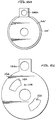
- Figure 16 is a sectional view of the sleeve 44a and the spool 121 described above assembled together in a housing 12.
- Housing 12 includes conduits 132, 134, 136 and 138 connected with control pressure C E , system pressure R, system return pressure P, and control pressure C R , respectively.
- Figure 17 is a sectional view taken along line 17-17 of Figure 16. This view shows a section through the spool at the channels 128 in combination with the sleeve at the location of disk 60. From this view it will be seen that channels 128 are aligned with large diagonal openings 70 and 72 but are not aligned with the passageways leading to the spool 121 from openings 74, 76, 78, and 80.
- Rotation of spool 121 a small amount in a counterclockwise direction will cause the large diagonal openings 70 and 72 to communicate through channels 128 with openings 74 and 78, respectively. Since channel 128 communicates with return pressure R (see Figures 9 and 13), rotation of the spool as described results in flow decreasing control pressure C E in conduit 132.
- Rotation of the spool 121 in the clockwise direction permits flow to the large diagonal openings 70 and 72 (Figure 17) from openings 76 and 80, respectively, which are part of elongated passageways running the length of the sleeve terminating at openings 78' and 74', respectively, and which thereby exhausts pressure C R from conduit 138 to return pressure conduit 134 (C R ).
- clockwise movement of spool 121 at the opposite end of the sleeve results in a connecting diagonal opening 72' with opening 80' and diagonal opening 70' with opening 76'. Since diagonals 70' and 72' are connected to conduit 136 carrying system supply pressure P, this effectively connects control pressure C E conduit 132 with supply pressure conduit 136.
- rotation of the spool 121 in a clockwise direction results in moving the actuator in a second direction which, in the case of the above described piston in a cylinder, would be such as to extend the actuating rod.
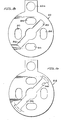
- Figure 19 is an assembly of disks somewhat similar to Figure 2 described above with Figure 20 being an end view of this assembly.
- the end blocks 56' and 58' are, or may be, identical to end blocks 56 and 58 of Figure 2.
- the disks immediately adjacent end blocks 56' and 58' are shown on Figure 21 at numeral 144.
- One disk 144 is installed with its tab 144a at the top of the left end of the sleeve assembly, and another such disk is installed reversed adjacent end block 58'.
- Disk 146' of Figure 23 is almost identical to disk 146 of Figure 22 except that the disk 146' includes a tab 146'a which is rotated 90° counterclockwise as compared with the tab 146a of disk 146.
- Disk 146 includes a center bore 148 in which a spool is received. Opening into center bore 148 are a plurality of slots communicating with openings 150, 152, 134, and 156, all of which form parts of passageways within the completed sleeve.
- slots 158 and 160 are also opening into center bore 148 which extend radially a greater distance from the center than the above described openings.
- slots 158 and 160 become exterior openings into the sleeve.
- the center disk 162 is shown in Figure 24. This disk has openings 164, 166, 168, and 170 corresponding to openings 150, 152, 154, and 156, respectively, in Figure 22, but with no openings into the center bore.
- the elongated passageway 176 is formed from opening 154 in disk 146, 168 in disk 162, 152' in disk 146', and 143 in the reversed disk 144 at the right end of the sleeve.
- This view also shows a small diameter bore 178 extending from the left end of the sleeve through the end block member 56' and through disk 144 which communicates with slot 158.
- a similar small diameter bore which is drilled through the reversed disk 144 but which is not utilized.
- Figure 26 is a side view showing the spool 180 which cooperates with the sleeve 171.
- a port is shown consisting of a rectangular opening 182 adjacent a circular bore 184, which openings are connected by means of a short slot all extending through the spool as shown on Figure 27, which is a cross-sectional view taken along line 27-27 of Figure 26, and Figure 28 which is a top view of spool 180.
- an additional port is shown rotated 90° from openings 182 and 184, which port is also formed of a rectangular opening 186 and a bore 188 connected by a small slot.
- Figure 29 is a cross-sectional view along lines 29-29 of Figure 28 and shows opening 186 extending across the width of the spool 180.
- the compound port arrangement provides a means for controlling flow with great precision, partic ⁇ larly ⁇ at the point of opening, since the bore is just slightly larger in diameter than the width of the rectangular opening; therefore, the initial valve opening is through an edge of the bore which can be lapped to very close tolerances to provide the desired initial flow pattern.
- a plurality of unnumbered longitudinal slots are shown in Figures 26 through 29 whose function is to assist in pressure balancing of the spool, as will be understood by those skilled in the art.
- FIG 30 is a cross-sectional view showing the spool 180 installed in the sleeve 171, both of which are installed in a housing 12'.
- This housing is the same as housing 12.
- the system pressure conduit P is shown at numeral 190
- the system return pressure R is carried in conduit 192
- controlled pressure C E to one side of the actuator at conduit 194
- controlled pressure C R to the other side of the actuator at conduit 196.
- Each of conduits 190, 192, 194, and 196 communicates with an annulus surrounding sleeve 171.
- return pressure conduit 192 is directly connected with the spool 180.
- Figure 31 is a cross-sectional view taken along line 31-31 of Figure 30 and shows the elongated slots 158 and 160 (Figure 22) which communicate with spool 180 and the port 188 extending through the spool. With the spool in the position shown, there is flow across the spool through port 188 but no flow from any of the openings 150, 152, 154 or 156 ( Figure 22) which form part of the elongated passages 174, 175, 176, or 177.
- Figure 32 is a cross-sectional view taken along line 32-32 of Figure 30. Fluid at system pressure P is connected through conduit 190 to an annulus 198 which surrounds the sleeve 171 so that this pressure is in communication through radial slots 158' and 160' with spool 180.
- Rotation of the spool 180 in a counterclockwise direction connects slot 160(R) to opening 177 and slot 158 to opening 174 which results in conduit 196 (C R ) being connected to return pressure (R) conduit 192.
- slot 158' (P) is connected to opening 175 and slot 160' is connected to opening 176.
- This connects control pressure C E in conduit 196 to system pressure (P) in conduit 190, causing the actuator to be moved in the opposite direction which may be the extended position.
- the direct drive servo valve described above provides the several advantages enumerated above as compared with the conventional electrohydraulic servo valve. It incorporates a somewhat complex manifold structure in the sleeve, but this structure is readily fabricated through the use of the stacked or assembled disks which are preferably formed either by electrical discharge milling or by photo-etching techniques.
Landscapes
- Engineering & Computer Science (AREA)
- Physics & Mathematics (AREA)
- Fluid Mechanics (AREA)
- Mechanical Engineering (AREA)
- General Engineering & Computer Science (AREA)
- Multiple-Way Valves (AREA)
- Servomotors (AREA)
Abstract
Description
- This invention relates to a direct drive servo valve.
- A direct drive servo valve includes a housing containing conduits connecting fluid from a high pressure source to and from a hydraulic actuator and includes a sleeve in the housing including passageways connected to the various conduits and a spool member movable to interconnect the passageways as desired to control the flow of operating fluid to the actuator, with motor means being employed to drive the spool.
- The usual servo valve for controlling hydraulic actuators includes a spool valve movable linearly to direct fluid to one side or the other of an actuating piston while permitting flow from the opposite side to a return or low pressure source. The spool member may be movable manually or it may be controlled by means of an electrohydraulic torque motor which receives electrical control signals from a control system. One disadvantage of such a system is that the electrohydraulic torque motor, since it includes a pair of fluid jets with a flapper member movable to open one jet and partially close the other, constantly leaks a certain amount of operating fluid and thus imposes a load on the pumping system. Another disadvantage is that such a torque motor drives a spool valve which is connected to both its input signal source and its output through a series of fluid conduits. This usually requires that the system incorporate at least a direct mechanical position feedback means and perhaps an electrical feedback to the torque motor as well. For a number of applications it would be advantageous if the electrical motor could drive the servo valve directly to avoid such a "floating" spool valve. And since the torque motor inherently has a rotary output but the desired servo valve output is linear, the rotary motion of the torque motor armature must be converted to a linear motion, accomplished by the jet and flapper structure discussed above which varies the fluid pressure on opposite ends of the spool valve to cause it to move linearly.
- The direct drive servo valve of the invention utilizes a rotary torque motor having a limited displacement which operates through an output shaft to directly drive the spool of a rotary servo valve. A torque tube is sealed at one end to the output shaft and at its opposite end to either the sleeve or housing and thereby provides the dual functions of sealing operating fluid away from the motor windings and of acting as a return spring to center the output shaft and spool in the desired null position. The rotatable valve structure consists of a housing containing a sleeve . made up of a number of annular disks having various patterns of flow passages therethrough, which disks are carefully arranged, radially aligned and brazed together with endcaps, and the assembly then machined to the desired diameter to expose the desired passageways which are aligned with conduits in the housing. The spool member is machined to the desired diameter to fit in the center of the sleeve and includes a series of channels which are rotated by the torque motor to provide the desired interconnections among the sleeve passageways.
- One advantage resulting from the invention is that the direct drive rotary valve arrangement eliminates the necessity of converting the torque motor rotary motion to linear motion.
- Another advantage is that the rotary arrangement facilitates pressure-balancing of the spool in that the spool can be made symmetrical with fluid pressure forces acting on opposite sides simultaneously to reduce the required operating forces.
- A further advantage of the present invention is that the torque tube is utilized not only as a seal but also as a centering spring to assure that the spool returns to null position with electrical power off.
- A further advantage is that the leakage of operating fluid referred to above is eliminated.
- A still further advantage is that the direct drive valve, although having rather complicated patterns of passageways in its sleeve structure, is amenable to production through the use of stacked disks having various patterns of cutouts made with electrical discharge milling (EDM) techniques or photo-etching techniques.
- Other objects and advantages will become apparent from the following specification taken in connection with the accompanying drawings in which: .
- Figure 1 is a perspective drawing, partially in section, of the torque motor portion of my direct drive valve;
- Figure lA is a perspective drawing, partially in section, of a valve structure operated by the torque motor of Figure 1.
- Figure 2 is a plan view showing the manner in which a number of disks are assembled to form the sleeve used in one embodiment of our invention;
- Figure 3 is an end view of the assembly shown in Figure 2;
- Figure 4 is a plan view of one of the end blocks shown in Figures 2 and 3;
- Figure 5 is a side view of the end block of Figure 4;
- Figures 6, 7, 8, 9 and 10 are plan views of disks shown in Figure 2;
- Figure 11 is a sectional view of a sleeve used in one embodiment of our invention and formed from the disks and end blocks described in Figures 4 through 10;
- Figure 12 is an end view of the sleeve of Figure 11;
- Figure 13 is a side view of a spool member usable with the sleeve of Figures 11 and 12;
- Figure 14 is a sectional view taken along lines 14-14 of Figure 13;
- Figure 15 is a sectional view taken along lines 15-15 of Figure 13;
- Figure 16 is a sectional view of an assembly including the sleeve of Figure 11 located in its housing and also the spool of Figure 13; .
- Figure 17 is a sectional view taken along line 17-17 of Figure 16;
- Figure 18 is a sectional view taken along line 18-18 of Figure 16;
- Figure 19 is a side view of an assembly of disks used in a second embodiment of our invention;
- Figure 20 is an end view of the assembly of Figure 19;
- Figures 21, 22, 23 and 24 are plan views of disk configuration used in the assembly of Figures 19 and 20;
- Figure 25 is a sectional view of a finished sleeve formed from the assembly of Figures 19 and 20;
- Figure 26 is a side view of a spool assembly adapted to be installed in the sleeve of Figure 25;
- Figure 27 is a sectional view taken along line 27-27 of Figure 26;
- Figure 28 is a top view of the spool of Figure 26;
- Figure 29 is a sectional view taken along line 29-29 of Figure 28;
- Figure 30 is a sectional view of an assembly including the sleeve of Figure 25 and the spool of Figures 26-29;
- Figure 31 is a sectional view taken along line 31-31 of Figure 30; and
- Figure 32 is a sectional view taken along line 32-32 of Figure 30.
- Referring now to Figure 1, it will be seen that this is a perspective drawing, partially in section, showing our direct drive valve assembly including the torque motor 10 which drives a spool in the
mechanical housing assembly 12. The torque motor includes ahousing 14 containingelectrical windings 16, amagnet structure 18, and arotatable armature member 20 which is supported in the housing inbearings left end armature 20 is sealed to atorque tube 26 which, in turn, is sealed to anoutput shaft 28. The opposite end oftorque tube 26 is sealed to a member 30 which is pinned or otherwise secured to thehousing 14. Member 30 may be, and preferably is, a part of the torque tube. With this arrangement, it will be understood that when thewindings 16 are energized thearmature 20 will rotate over a small arc, carrying the output shaft and the left end oftorque tube 26 while the right end oftorque tube 26 is securely held to member 30.Output shaft 28 is secured to aflexible coupling member 32 which, in turn, is secured to the rotatable spool inhousing 12. It will be observed thathousing 12 includes a plurality of ports,port 34 being connected to a source of operating fluid under high pressure (P), port 36 being connected to the return side of said source (R), port 38 being connected to supply pressure to drive an associated actuator in one direction such as to extend it (CE) andport 40 being connected to the opposite side of said actuator to drive it in the opposite direction such as to retract it (CR). - Figure la constitutes an extension of the sectional structure of Figure 1 in that the
output shaft 28 is shown connected to theflexible coupling 32 which, in turn, is connected to aspool member 42 rotatable within asleeve 44 shown in parts in this particular schematic presentation. In the view pictured, it is shown that operating fluid under high pressure enters the sleeve through anopening 46 where it finds a flow path along a channel in thespool 42 permitting it to reach a radial slot 48 in thesleeve 44 communicating with return pressure (CR) at port 40 (Figure 1). Flow directed toport 40 will also flow along the sleeve toward aport 50, but this port is blocked. At the same time the spool will be in a position to open aport 52 which permits flow from the actuator (CE) to the return port 36 (R). Again, the flow from the extend side of the actuator CE flows along the spool to aport 54 but flows no farther because this port is blocked by thespool 42. This, of course, is only one of the patterns of flow through this valve, and others will be discussed below. - Figures 2 and 3 depict the arrangement of parts making up a typical sleeve assembly for our direct drive valve, Figure 2 being a side
view showing endcaps disk members endcap member 56 as well as atab 60a forming part ofdisk 60 as will appear hereafter. Also visible in this view istab 64a forming part ofdisk 64, but similar tabs aligned with 64a are behind it forming parts ofdisks 62 and 60' appearing near the right end of the assembly of Figure 2. The center bores of these tabs are drilled slightly off- center so as to produce this desired misalignment when the disks are assembled to indicate which disks are reversed. - Figures 4 and 5 are plan and side views, respectively, of the end blocks of the assembly shown in Figure 2. It will be seen that these are simple annular structures with a flat at the top as shown in Figure 3.
- Figure 6 is an enlarged plan view of
disk 60 shown in Figure 2 which includestab 60a at the top with a center bore located slightly off center of the tab but centered on a radius of thedisk 60. This view ofdisk 60 shows a center bore 68 communicating with opposite radial passages oropenings openings Openings openings openings tab 60a relative to the rest of the openings in the disk. Thus, tab 60'a is positioned at approximately 900 or in alignment with opening 76'. - From the foregoing, it will be clear that when disk 60' is placed in the stack of Figure 2 in the position shown, with the tab 60'a at the top, one significant difference becomes apparent. The larger openings 74' and 78' are now at the 90° and 270° positions so that this is where the exterior openings will appear when the sleeve is trimmed to its desired dimensions. The elongated large area slots 70' and 72' will also rotate 90° to the 1350 - 315° positions.
- Figure 8 is a plan view of the two disks indicated at
number 62 in Figure 2. It has a tab 62a at the top which is also slightly out of alignment with the center of the disk. This disk has a plurality oflarge area openings disk 64a (see Figure 3). Reversing of this disk will place the elongatedlarge area slots disk 64 which is quite similar todisk 62 except for the elongatedlarge area slots 94 and 96 which are oriented similarly toslots slots disks 64 are located in two positions on the assembly of Figure 2 with the disk toward the right being reversed from the position shown so that thelarge area slots 94 and 96 are also reversed. - The
single disk 66 is shown on Figure 10. In addition to thecenter opening 98, it hasopenings center sleeve opening 98. - The composite of the disks described above stacked and brazed together as shown in Figure 2 is then machined to produce the
sleeve 44a shown in Figure 11, which is a vertical section through the sleeve. In this view, thevertical openings small slot 107 communicatingopening 80 with theinternal spool chamber 109 is also visible. The openings to actuator port CR (part 40, Figure 1) at the right end of thesleeve 44a are at 90° with respect to this section and thus not visible, but openings to thecenter spool chamber 109 are visible. The openings at top and bottom of the disks described above appear in this sleeve as elongatedaxial passageways center spool chamber 109 are a firstelongated slot 112 resulting from the elongated large area openings ofdisks such slot 114 resulting from the large area elongated openings in reverseddisks - Figure 12 is an end view of the sleeve structure shown in Figure 11, showing the
central spool chamber 109 and alarge diameter flange 116 appearing at the right end of Figure 11 which assists in securing the sleeve to the housing. Asmall port 118 communicates operating fluid at return pressure withchamber 120 at the end of the sleeve. System pressure (Cp) or operating pressure CE is contained by means of lap-fitting of the spool to the sleeve; therefore, there is some leakage across the spool which will tend to increase the fluid pressure acting on the end of the spool and make operation more difficult. To prevent this pressure build-up, port 118'permits any such increased pressure to be drained to return pressure. - Figure 13 is a side view of a
spool 121 which is rotatable insleeve 44a. This spool carries lands 122, 124, and 126.Land 124 contains grooves to assist in balancing the pressures P and R on the spool.Land 122 containschannels 128 which can be oriented to connect control pressures CE and CR to return pressure R. Similarly,land 126 containschannels 130 which can be moved to connect control pressure CR and CE to system pressure P. These channels are shown in Figures 14 and 15 which are cross-sectional views through lines 14-14 and 15-15 of Figure 13, respectively. It will be observed that each channel has sides which are only slightly displaced from radii and parallel thereto, and these slots are movable to communicate with the small passageways shown at the 0°, 900, 1800, and 2700 positions ondisks 60 and 60'.Channels 128 are always in communication with the large elongated slots 112 (Figure 11), andchannels 130 are always in communication withslots 114. - Figure 16 is a sectional view of the
sleeve 44a and thespool 121 described above assembled together in ahousing 12.Housing 12 includesconduits channels 128 in combination with the sleeve at the location ofdisk 60. From this view it will be seen thatchannels 128 are aligned with largediagonal openings spool 121 fromopenings diagonal openings channels 128 withopenings channel 128 communicates with return pressure R (see Figures 9 and 13), rotation of the spool as described results in flow decreasing control pressure CE inconduit 132. - Referring to Figure 18, rotation of the
spool 121 in the same counterclockwise direction results in connecting large diagonal openings 70' and 72' with openings 74' and 78' which connect with the controlled pressure CR conduit 138. Since the large diagonal openings connect with system supply pressure P (Figures 9 and 13), the operating fluid inpassage 138 is increased to supply pressure throughconduit 136. Thus, movement of the spool in a counterclockwise direction will result in moving the actuator in a first direction which, in the case of a conventional piston in a cylinder connected to an actuating rod, may be such as to retract the actuating rod. - Rotation of the
spool 121 in the clockwise direction permits flow to the largediagonal openings 70 and 72 (Figure 17) fromopenings conduit 138 to return pressure conduit 134 (CR). At the same time, clockwise movement ofspool 121 at the opposite end of the sleeve (Figure 18) results in a connecting diagonal opening 72' with opening 80' and diagonal opening 70' with opening 76'. Since diagonals 70' and 72' are connected toconduit 136 carrying system supply pressure P, this effectively connects control pressure CE conduit 132 withsupply pressure conduit 136. Thus, rotation of thespool 121 in a clockwise direction results in moving the actuator in a second direction which, in the case of the above described piston in a cylinder, would be such as to extend the actuating rod. - A somewhat different embodiment of my invention is discussed below. In this embodiment, operation is essentially the same as that discussed above, but the details of the spool and sleeve are different. Figure 19 is an assembly of disks somewhat similar to Figure 2 described above with Figure 20 being an end view of this assembly. The end blocks 56' and 58' are, or may be, identical to end
blocks numeral 144. Onedisk 144 is installed with itstab 144a at the top of the left end of the sleeve assembly, and another such disk is installed reversed adjacent end block 58'. Each ofdisks 144 hasopenings small bore 178 just above the center opening. The next disks . toward the center are shown on Figures 22 and 23. Disk 146' of Figure 23 is almost identical todisk 146 of Figure 22 except that the disk 146' includes a tab 146'a which is rotated 90° counterclockwise as compared with thetab 146a ofdisk 146.Disk 146 includes a center bore 148 in which a spool is received. Opening into center bore 148 are a plurality of slots communicating withopenings elongated slots slots - The
center disk 162 is shown in Figure 24. This disk hasopenings openings - The above described disks are brazed together as described above and the
entire sleeve assembly 171 machined to the configuration shown in the sectional drawing, Figure 25, which shows the internal bore 172, the vertical radial passageways resulting fromslots 158 and 160 (Figure 22) and the opening to the horizontal passageway 160' appearing in disk 146' and also the adjacent slots communicating with chambers 152' and 154'. In this view theelongated passageways Passageway 174 is formed from opening 145 in disk 144 (Figure 21), opening 156 in disk 146 (Figure 22), opening 170 in disk 162 (Figure 24), and opening 154' in disk 146' (Figure 23). Similarly, theelongated passageway 176 is formed from opening 154 indisk disk 162, 152' indisk 146', and 143 in the reverseddisk 144 at the right end of the sleeve. This view also shows a small diameter bore 178 extending from the left end of the sleeve through the end block member 56' and throughdisk 144 which communicates withslot 158. At the opposite end of thesleeve 171 is a similar small diameter bore which is drilled through the reverseddisk 144 but which is not utilized. - Figure 26 is a side view showing the
spool 180 which cooperates with thesleeve 171. On this view a port is shown consisting of arectangular opening 182 adjacent acircular bore 184, which openings are connected by means of a short slot all extending through the spool as shown on Figure 27, which is a cross-sectional view taken along line 27-27 of Figure 26, and Figure 28 which is a top view ofspool 180. In Figure 28 an additional port is shown rotated 90° fromopenings rectangular opening 186 and abore 188 connected by a small slot. Figure 29 is a cross-sectional view along lines 29-29 of Figure 28 and shows opening 186 extending across the width of thespool 180. The compound port arrangement provides a means for controlling flow with great precision, particυlarly ` at the point of opening, since the bore is just slightly larger in diameter than the width of the rectangular opening; therefore, the initial valve opening is through an edge of the bore which can be lapped to very close tolerances to provide the desired initial flow pattern. A plurality of unnumbered longitudinal slots are shown in Figures 26 through 29 whose function is to assist in pressure balancing of the spool, as will be understood by those skilled in the art. - Figure 30 is a cross-sectional view showing the
spool 180 installed in thesleeve 171, both of which are installed in ahousing 12'. This housing is the same ashousing 12. In this drawing the system pressure conduit P is shown atnumeral 190, the system return pressure R is carried inconduit 192, controlled pressure CE to one side of the actuator atconduit 194 and controlled pressure CR to the other side of the actuator atconduit 196. Each ofconduits annulus surrounding sleeve 171. In this view, which is a vertical section through thesleeve 171, it will be seen thatreturn pressure conduit 192 is directly connected with thespool 180. Figure 31 is a cross-sectional view taken along line 31-31 of Figure 30 and shows theelongated slots 158 and 160 (Figure 22) which communicate withspool 180 and theport 188 extending through the spool. With the spool in the position shown, there is flow across the spool throughport 188 but no flow from any of theopenings elongated passages conduit 190 to anannulus 198 which surrounds thesleeve 171 so that this pressure is in communication through radial slots 158' and 160' withspool 180. - Operation of the assembly of Figure 30 is similar to that described above. Referring to Figures 31 and 32, a small clockwise rotation of
spool 180 connectsslot 158 to opening 175 and slot 160 toopening 176. This connects conduit 194 (CE) to return pressure (R). This same rotation causes slot 158' to be connected to opening 177 and slot 160' toopening 174, which causes system pressure (P) inconduit 190 to be connected to conduit 196 (CR). This results in moving the associated actuator in a given direction which may be the retracted position. - Rotation of the
spool 180 in a counterclockwise direction connects slot 160(R) toopening 177 and slot 158 to opening 174 which results in conduit 196 (CR) being connected to return pressure (R)conduit 192. At the same time, slot 158' (P) is connected to opening 175 and slot 160' is connected toopening 176. This connects control pressure CE inconduit 196 to system pressure (P) inconduit 190, causing the actuator to be moved in the opposite direction which may be the extended position. - From the foregoing it will be appreciated that the direct drive servo valve described above provides the several advantages enumerated above as compared with the conventional electrohydraulic servo valve. It incorporates a somewhat complex manifold structure in the sleeve, but this structure is readily fabricated through the use of the stacked or assembled disks which are preferably formed either by electrical discharge milling or by photo-etching techniques.
Claims (11)
Applications Claiming Priority (2)
| Application Number | Priority Date | Filing Date | Title |
|---|---|---|---|
| US40360482A | 1982-08-02 | 1982-08-02 | |
| US403604 | 1982-08-02 |
Publications (2)
| Publication Number | Publication Date |
|---|---|
| EP0102884A1 true EP0102884A1 (en) | 1984-03-14 |
| EP0102884B1 EP0102884B1 (en) | 1986-07-30 |
Family
ID=23596380
Family Applications (1)
| Application Number | Title | Priority Date | Filing Date |
|---|---|---|---|
| EP83401596A Expired EP0102884B1 (en) | 1982-08-02 | 1983-08-02 | Direct drive servo valve |
Country Status (3)
| Country | Link |
|---|---|
| EP (1) | EP0102884B1 (en) |
| JP (1) | JPS5947508A (en) |
| DE (1) | DE3364944D1 (en) |
Cited By (13)
| Publication number | Priority date | Publication date | Assignee | Title |
|---|---|---|---|---|
| WO1990002884A1 (en) * | 1988-09-16 | 1990-03-22 | Fairey Hydraulics Limited | Direct drive valve |
| EP0393345A3 (en) * | 1989-04-19 | 1991-04-10 | Bw Hydraulik Gmbh | Hydraulic control device |
| FR2756022A1 (en) * | 1996-11-15 | 1998-05-22 | Samm Societe D Applic Des Mach | Electro-hydraulic servo-valve controlling actuator or motor |
| EP1490614A4 (en) * | 2002-02-27 | 2005-06-22 | Aser Tech Co Ltd | Four-way reversing valve |
| EP1488148A4 (en) * | 2002-02-27 | 2005-06-22 | Aser Tech Co Ltd | Vaned spool type directional control valve and four-way reversible valve for cooling cycle system using the same |
| WO2013126105A1 (en) * | 2012-02-23 | 2013-08-29 | Moog Inc. | Integrated structure electro-hydraulic valve |
| US9228596B2 (en) | 2013-09-23 | 2016-01-05 | Moog Inc. | Direct drive rotary valve |
| US9309900B2 (en) | 2012-02-09 | 2016-04-12 | Moog Inc. | Electro-hydraulic servo valve |
| CN106930993A (en) * | 2015-12-29 | 2017-07-07 | 博世力士乐(常州)有限公司 | Reversal valve |
| WO2020161486A1 (en) * | 2019-02-05 | 2020-08-13 | Domin Fluid Power Limited | Rotary servo valve |
| CN113162313A (en) * | 2021-04-15 | 2021-07-23 | 浙大城市学院 | Two-dimensional motor and servo valve |
| GB2581162B (en) * | 2019-02-05 | 2022-12-14 | Domin Fluid Power Ltd | Rotary servo valve |
| RU228295U1 (en) * | 2024-06-07 | 2024-08-22 | Общество с ограниченной ответственностью "Научнопроизводственное Предприятие Техмашконструкция" | SPOOL VALVE |
Citations (4)
| Publication number | Priority date | Publication date | Assignee | Title |
|---|---|---|---|---|
| US2807280A (en) * | 1953-07-20 | 1957-09-24 | Arthur E Kittredge | Program control valve |
| DE1225933B (en) * | 1960-11-01 | 1966-09-29 | Walter D Ludwig | Control slide with a flat, rotatable control part, which can be rotated without contact by an electromagnetic field |
| US3504703A (en) * | 1967-12-07 | 1970-04-07 | Edward Bozoyan | Rotary spool valve |
| US3598152A (en) * | 1968-06-26 | 1971-08-10 | Dowty Technical Dev Ltd | Piston valves |
-
1983
- 1983-07-29 JP JP13794483A patent/JPS5947508A/en active Pending
- 1983-08-02 DE DE8383401596T patent/DE3364944D1/en not_active Expired
- 1983-08-02 EP EP83401596A patent/EP0102884B1/en not_active Expired
Patent Citations (4)
| Publication number | Priority date | Publication date | Assignee | Title |
|---|---|---|---|---|
| US2807280A (en) * | 1953-07-20 | 1957-09-24 | Arthur E Kittredge | Program control valve |
| DE1225933B (en) * | 1960-11-01 | 1966-09-29 | Walter D Ludwig | Control slide with a flat, rotatable control part, which can be rotated without contact by an electromagnetic field |
| US3504703A (en) * | 1967-12-07 | 1970-04-07 | Edward Bozoyan | Rotary spool valve |
| US3598152A (en) * | 1968-06-26 | 1971-08-10 | Dowty Technical Dev Ltd | Piston valves |
Cited By (19)
| Publication number | Priority date | Publication date | Assignee | Title |
|---|---|---|---|---|
| WO1990002884A1 (en) * | 1988-09-16 | 1990-03-22 | Fairey Hydraulics Limited | Direct drive valve |
| EP0393345A3 (en) * | 1989-04-19 | 1991-04-10 | Bw Hydraulik Gmbh | Hydraulic control device |
| FR2756022A1 (en) * | 1996-11-15 | 1998-05-22 | Samm Societe D Applic Des Mach | Electro-hydraulic servo-valve controlling actuator or motor |
| EP1490614A4 (en) * | 2002-02-27 | 2005-06-22 | Aser Tech Co Ltd | Four-way reversing valve |
| EP1488148A4 (en) * | 2002-02-27 | 2005-06-22 | Aser Tech Co Ltd | Vaned spool type directional control valve and four-way reversible valve for cooling cycle system using the same |
| US6983760B2 (en) | 2002-02-27 | 2006-01-10 | Aser Tech Co., Ltd. | Vaned spool type directional control valve and four-way reversible valve for cooling cycle system using the same |
| US9309900B2 (en) | 2012-02-09 | 2016-04-12 | Moog Inc. | Electro-hydraulic servo valve |
| US10024444B2 (en) | 2012-02-23 | 2018-07-17 | Moog Inc. | Integrated structure electro-hydraulic valve |
| WO2013126105A1 (en) * | 2012-02-23 | 2013-08-29 | Moog Inc. | Integrated structure electro-hydraulic valve |
| CN104246238A (en) * | 2012-02-23 | 2014-12-24 | 莫戈公司 | Integrated structure electro-hydraulic valve |
| US9228596B2 (en) | 2013-09-23 | 2016-01-05 | Moog Inc. | Direct drive rotary valve |
| CN106930993A (en) * | 2015-12-29 | 2017-07-07 | 博世力士乐(常州)有限公司 | Reversal valve |
| WO2020161486A1 (en) * | 2019-02-05 | 2020-08-13 | Domin Fluid Power Limited | Rotary servo valve |
| CN113710902A (en) * | 2019-02-05 | 2021-11-26 | 多明流体动力有限公司 | Rotary servo valve |
| GB2581162B (en) * | 2019-02-05 | 2022-12-14 | Domin Fluid Power Ltd | Rotary servo valve |
| US11761461B2 (en) | 2019-02-05 | 2023-09-19 | Domin Fluid Power Limited | Rotary servo valve |
| CN113710902B (en) * | 2019-02-05 | 2024-08-30 | 多明流体动力有限公司 | Rotary servo valve |
| CN113162313A (en) * | 2021-04-15 | 2021-07-23 | 浙大城市学院 | Two-dimensional motor and servo valve |
| RU228295U1 (en) * | 2024-06-07 | 2024-08-22 | Общество с ограниченной ответственностью "Научнопроизводственное Предприятие Техмашконструкция" | SPOOL VALVE |
Also Published As
| Publication number | Publication date |
|---|---|
| JPS5947508A (en) | 1984-03-17 |
| DE3364944D1 (en) | 1986-09-04 |
| EP0102884B1 (en) | 1986-07-30 |
Similar Documents
| Publication | Publication Date | Title |
|---|---|---|
| EP0102884B1 (en) | Direct drive servo valve | |
| US4794845A (en) | Direct drive rotary servo valve | |
| US4646786A (en) | Fluid control valves with angled metering ports | |
| US4359064A (en) | Fluid power control apparatus | |
| US4658859A (en) | Valve spool with cross drill ports | |
| US4308892A (en) | Rotary valve | |
| US5697401A (en) | Hydraulic servovalve | |
| US2964018A (en) | Electro-hydraulic servo valve | |
| JPH04300401A (en) | Multiplexed hydraulic control system | |
| EP3921550B1 (en) | Rotary servo valve | |
| US4779648A (en) | Pilot controlled valves | |
| US4922964A (en) | Servovalve construction | |
| US4683915A (en) | Pilot controlled valves | |
| US4566479A (en) | Spool member of a multi-way-valve | |
| US3007494A (en) | Rotary fluid valve | |
| US4700747A (en) | Proportional hydraulic distributor | |
| US3342213A (en) | Hydraulic apparatus | |
| US3023779A (en) | Fluid flow control valve | |
| JPS604602A (en) | Assembled value having independent pump and function controlspool | |
| US3717175A (en) | Selector valves | |
| US2897792A (en) | Servo valves | |
| JP3199331B2 (en) | Rotary control valve | |
| US12448990B2 (en) | Two-stage servo valve | |
| US4056125A (en) | Extended life structure for spool valve | |
| JP3473982B2 (en) | Rotary valve for vibration generation and vibration generator |
Legal Events
| Date | Code | Title | Description |
|---|---|---|---|
| PUAI | Public reference made under article 153(3) epc to a published international application that has entered the european phase |
Free format text: ORIGINAL CODE: 0009012 |
|
| AK | Designated contracting states |
Designated state(s): DE FR GB |
|
| 17P | Request for examination filed |
Effective date: 19840704 |
|
| RAP1 | Party data changed (applicant data changed or rights of an application transferred) |
Owner name: ALLIED CORPORATION |
|
| GRAA | (expected) grant |
Free format text: ORIGINAL CODE: 0009210 |
|
| AK | Designated contracting states |
Kind code of ref document: B1 Designated state(s): DE FR GB |
|
| REF | Corresponds to: |
Ref document number: 3364944 Country of ref document: DE Date of ref document: 19860904 |
|
| ET | Fr: translation filed | ||
| PLBE | No opposition filed within time limit |
Free format text: ORIGINAL CODE: 0009261 |
|
| STAA | Information on the status of an ep patent application or granted ep patent |
Free format text: STATUS: NO OPPOSITION FILED WITHIN TIME LIMIT |
|
| 26N | No opposition filed | ||
| PG25 | Lapsed in a contracting state [announced via postgrant information from national office to epo] |
Ref country code: GB Free format text: LAPSE BECAUSE OF NON-PAYMENT OF DUE FEES Effective date: 19880802 |
|
| PG25 | Lapsed in a contracting state [announced via postgrant information from national office to epo] |
Ref country code: FR Free format text: LAPSE BECAUSE OF NON-PAYMENT OF DUE FEES Effective date: 19890428 |
|
| PG25 | Lapsed in a contracting state [announced via postgrant information from national office to epo] |
Ref country code: DE Effective date: 19890503 |
|
| GBPC | Gb: european patent ceased through non-payment of renewal fee | ||
| REG | Reference to a national code |
Ref country code: FR Ref legal event code: ST |