EP0102743A2 - Method and apparatus for conveying substrate in continuous multicolor printing press - Google Patents
Method and apparatus for conveying substrate in continuous multicolor printing press Download PDFInfo
- Publication number
- EP0102743A2 EP0102743A2 EP83304357A EP83304357A EP0102743A2 EP 0102743 A2 EP0102743 A2 EP 0102743A2 EP 83304357 A EP83304357 A EP 83304357A EP 83304357 A EP83304357 A EP 83304357A EP 0102743 A2 EP0102743 A2 EP 0102743A2
- Authority
- EP
- European Patent Office
- Prior art keywords
- substrate
- belt
- printing
- conveying
- mesh belt
- Prior art date
- Legal status (The legal status is an assumption and is not a legal conclusion. Google has not performed a legal analysis and makes no representation as to the accuracy of the status listed.)
- Withdrawn
Links
Images

Classifications
-
- B—PERFORMING OPERATIONS; TRANSPORTING
- B41—PRINTING; LINING MACHINES; TYPEWRITERS; STAMPS
- B41F—PRINTING MACHINES OR PRESSES
- B41F15/00—Screen printers
- B41F15/14—Details
- B41F15/16—Printing tables
- B41F15/18—Supports for workpieces
- B41F15/20—Supports for workpieces with suction-operated elements
-
- B—PERFORMING OPERATIONS; TRANSPORTING
- B41—PRINTING; LINING MACHINES; TYPEWRITERS; STAMPS
- B41F—PRINTING MACHINES OR PRESSES
- B41F13/00—Common details of rotary presses or machines
- B41F13/02—Conveying or guiding webs through presses or machines
Definitions
- This invention relates to a method and apparatus for conveying a substrate in a continuous multi-color printing press, and more specifically, to a method and apparatus for conveying a substrate to be printed to a printing zone by utilizing a suction pressure.
- various printing devices such as a gravure printing press and a rotary offset printing press have been used as_means for continuously performing multicolor printing on a long strip of substrate such as paper, various films and metallic foils.
- a different example of such continuous multicolor screen printing is automatic screen printing of textile products.
- an endless belt is used to convey the substrate, and by using a suitable adhesive, the substrate is adhered to the endless belt.
- the substrate and the belt thus become a unitary structure, and intermittent driving is carried out at predetermined intervals of feed.
- the accuracy of feed and hence the accuracy of registering can be maintained high.
- the substrate is paper, a film, or the like, it can be adhered to a belt but it is difficult or impossible to peel it therefrom. Accordingly, a conveying method using a belt cannot be employed.
- a method for conveying a substrate to be printed which comprises stretching an endless belt over a pair of conveyor rollers, placing the substrate on the belt, and conveying the substrate to a printing zone by the driving of the belt, characterized in that a number of apertures are formed on the endless belt, a negative pressure is applied to the underside of the belt on the substrate-conveying side, and the substrate, while in intimate contact with the endless belt, is conveyed to the printing zone as an integral unit with the endless belt without a deviation in position.
- a conveying device wherein a mesh belt is used as said endless belt, a suction table communicating with a suction device is provided below the conveying zone of the mesh belt, and the substrate is conveyed as an integral unit with the mesh belt by a suction force.
- the present invention is characterized by the fact that instead of the endless conveyor belt in an automatic screen printing machine, an endless metallic mesh belt is used as a means for conveying, and a substrate is always sucked to, and held on, the metallic mesh belt during moving and stopping by a suction pressure continuously applied by a suction table fixedly provided below the mesh belt, and therefore conveyed integrally with the mesh belt, and the position of the substrate during moving is secured even during stoppage.
- a drive roller 2 is provided rearwardly in the advancing direction of a substrate 1 to be printed, and a driven roller is provided in parallel thereto forwardly in the same direction.
- An endless metallic mesh belt 4 is stretched over these rollers. Intermittent rotation is given to the drive roller 2 by a drive motor 5 through a worm 6 and a worm gear 7, and the corresponding intermittent feed is imparted to the mesh belt 4.
- the method of intermittent feed may be any desired one which is disclosed, for example, in Japanese Patent Publication No. 24427/1980.
- the important characteristic feature of this invention is that the substrate 1 is conveyed to a printing zone P by using the mesh belt 4, and suction tables 8,8, Vietnamese are provided below the mesh belt 4 (at the upper position in the drawing) on the conveying side.
- the suction tables 8, 8, Vietnamese are connected to a vacuum pump or air discharge device 10 through a pipe 9.
- the suction tables 8 are fixed to a machine stand (not shown) at such relative positions that they are close to the underside of the mesh belt 4 on the conveying side.
- a number of apertures 8A are provided substantially evenly on the entire upper surfaces of the suction tables 8, and the suction pipe 9 is connected to the undersides and side surfaces of these suction tables 8 and thus leads to the vacuum pump or air discharging device 10.
- the inside of a hollow chamber 8B becomes vacuum or is maintained under a negative pressure.
- the vacuum pump or air discharging device 10 when the vacuum pump or air discharging device 10 is operated in conveying the substrate 1 on the mesh belt 4, the pressure of the hollow chamber 8B becomes vacuum or netative. Hence, the substrate 1 remains in intimate contact with the mesh belt 4, and is conveyed smoothly to the printing zone without a trouble such as a deviation in position.
- Apertures 4 are formed on the mesh belt 4. To impart a sucking effect to the entire surface of the substrate 1 and to secure a smooth printing surface, the mesh size is advantageously small.
- the mesh belt 4 is produced by the same method as in the production of a rotary screen mesh by electroplating which is now widely used. By such a method, a mesh belt having a size of 40 to 200 mesh can usually be obtained. Various other types of mesh belts made of metals or non-metals may be used. But the one obtained by the electroplating method is practical because its frictional resistance to the suction tables 8 is good, apertures 4A can be formed easily and it is completely endless.
- a suction force acts on the entire surface of the substrate by the operation of the vacuum pump or air discharging device 10, the substrate 1 is conveyed to the printing zone P while it is maintained in intimate contact with the mesh belt 4 as a unit.
- the substrate 1 is fixed to the surface of the mesh belt 4 in intimate contact therewith.
- printing can be smoothly and accurately carried out on the substrate without positional deviation, stretching, contraction, etc.
- a plurality of planographic printing devices 11 are arranged at intervals corresponding to the feed repeats, and between the planographic screen printing devices 11, an intermediate drying device 12 is provided as required. Thus, printing and drying are carried out for each color.
- the substrate 1 is intermittently driven as a unit with the mesh belt 4 by the aforesaid sucking action. After printing the required number of colors, the substrate 1 is separated from the mesh belt 4, and after a final drying device 13, is subjected to a wind-up or other steps.
- the suction tables 8 are provided in the divided state, but they may be provided as a one-piece structure. It is sufficient that they are arranged such that a sucking effect is produced over the entire area of the substrate 1 from before the start of printing to the end of printing, and during this time, stretching, contraction or slipping of the substrate 1 is prevented.
- rotary screen printing devices 15 are provided at equal intervals. Printing and intermediate drying are carried out for each color, and after final drying, the next step sets in.
- the mesh belt 4 and the substrate 1 are driven continuously. Receiver rollers 16 are required to be provided below the rotary screen devices 15 through the substrate 1 and the mesh belt 4.
- Figure 5 shows another embodiment of planographic screen printing in which the feed repeat is large, or the number of colors is larger, and thus a longer printing area is required.
- the mesh belt 4 is obtained by the electroplating method as mentioned above. To make it completely endless, its circumferential length is naturally limited. When the repeat is large or the number of colors is large, the length of the mesh belt 4 will be insufficient. To avoid this, the mesh belt 4 and the driving device therefor may be composed of a plurality of units which are then linked to each other and operated, as shown in Figure 5.
- the mesh belt 4, the drive roll, the driven roll and the suction tables are the same as in Figure 1, but the driving of the motor 5 reaches the drive roller 2 of each unit through a decelerater 17 such as a worm gear, and the individual units are synchronously operated through a line shaft 18.
- a decelerater 17 such as a worm gear
- This method can of course be used in the case of the rotary screen printing shown in Figure 4.
- the present invention is further characterized by the fact that a suction force is always exerted on the substrate irrespective of whether the mesh belt is moving or at a stop. Because of this characteristic, the sucking effect exists over the entire length of the printing zone whether the suction table is composed of divided units, or is a long one-piece structure. In - other words, the suction tables are arranged such that the substrate can be conveyed without stretching, contraction, vibration or slippage from before the start of printing to the end of printing.
Landscapes
- Engineering & Computer Science (AREA)
- Mechanical Engineering (AREA)
- Screen Printers (AREA)
- Belt Conveyors (AREA)
- Delivering By Means Of Belts And Rollers (AREA)
- Advancing Webs (AREA)
- Supply, Installation And Extraction Of Printed Sheets Or Plates (AREA)
- Coloring (AREA)
Abstract
Description
- This invention relates to a method and apparatus for conveying a substrate in a continuous multi-color printing press, and more specifically, to a method and apparatus for conveying a substrate to be printed to a printing zone by utilizing a suction pressure.
- Generally, various printing devices such as a gravure printing press and a rotary offset printing press have been used as_means for continuously performing multicolor printing on a long strip of substrate such as paper, various films and metallic foils.
- In a screen printing method by a stencil, however, no proper method has been available for conveying a substrate to be printed in order to secure accuracy of registering. Thus, multicolor screen printing is carried out by using a sheet-like substrate and exchanging the plate for each color, or by pulling the substrate intermittently by a predetermined length in the rear portion of a printing zone. Accordingly, in the former method, the productivity is naturally very low, and a long strip of substrate cannot at all be printed. According to the latter method, the substrate stretches or contracts owing to a tension exerted thereon. In order to perform precise printing, the type of the substrate is restricted, and an elaborate apparatus or control system is required in order to maintain the feed tension of the substrate constant.
- A different example of such continuous multicolor screen printing is automatic screen printing of textile products. In this process, an endless belt is used to convey the substrate, and by using a suitable adhesive, the substrate is adhered to the endless belt. The substrate and the belt thus become a unitary structure, and intermittent driving is carried out at predetermined intervals of feed. Thus, the accuracy of feed and hence the accuracy of registering can be maintained high. However, when the substrate is paper, a film, or the like, it can be adhered to a belt but it is difficult or impossible to peel it therefrom. Accordingly, a conveying method using a belt cannot be employed.
- It is an object of this invention to provide a method and apparatus for conveying a substrate in a continuous multicolor screen printing press with a high printing accuracy by employing the same conveying method as in an automatic screen printing machine even when the substrate is one which cannot be conveyed by an endless belt while adhering thereto.
- According to one aspect of this invention there is provided a method for conveying a substrate to be printed which comprises stretching an endless belt over a pair of conveyor rollers, placing the substrate on the belt, and conveying the substrate to a printing zone by the driving of the belt, characterized in that a number of apertures are formed on the endless belt, a negative pressure is applied to the underside of the belt on the substrate-conveying side, and the substrate, while in intimate contact with the endless belt, is conveyed to the printing zone as an integral unit with the endless belt without a deviation in position.
- According to another aspect of this invention, there is provided, in a continuous multicolor printing press for continuously performing multicolor printing on a substrate by placing the substrate on an endless belt stretched over a pair of conveyor rollers and conveying the substrate to a printing zone, a conveying device wherein a mesh belt is used as said endless belt, a suction table communicating with a suction device is provided below the conveying zone of the mesh belt, and the substrate is conveyed as an integral unit with the mesh belt by a suction force. BRIEF DESCRIPTION OF. THE-ACCOMPANYING DRAWINGS
- Figure 1 is a view showing an example of applying the present invention to printing by a planographic screen;
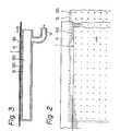
- Figures 2 and 3 are views showing the structures and arrangement of a mesh belt and a suction table in this invention;
- Figure 4 is a view showing the case of applying this invention to printing by a rotary screen; and
- Figure 5 is a view showing another embodiment of the application of this invention to planographic screen printing.
- The present invention is characterized by the fact that instead of the endless conveyor belt in an automatic screen printing machine, an endless metallic mesh belt is used as a means for conveying, and a substrate is always sucked to, and held on, the metallic mesh belt during moving and stopping by a suction pressure continuously applied by a suction table fixedly provided below the mesh belt, and therefore conveyed integrally with the mesh belt, and the position of the substrate during moving is secured even during stoppage. This characteristic feature leads to the following advantages.
-
- (1) The accuracy of feed independent from the degree of stretching or contraction of the substrate can be obtained. Hence, printing with a high accuracy of registering can be performed on any materials.
- (2) Since the substrate and the mesh belt as the conveying means are completely integrated over the entire length of the printing zone, a tension regulating device can be simplified both at the substrate delivery and take-up portions.
- Accordingly, continuous multi-color screen printing can be performed efficiently with a high accuracy.
- The present invention is described below with reference to the specific embodiments shown in the attached drawings.
- In Figure 1 showing an example of applying the conveying apparatus of this invention to planographic screen printing, a
drive roller 2 is provided rearwardly in the advancing direction of asubstrate 1 to be printed, and a driven roller is provided in parallel thereto forwardly in the same direction. An endlessmetallic mesh belt 4 is stretched over these rollers. Intermittent rotation is given to thedrive roller 2 by adrive motor 5 through aworm 6 and aworm gear 7, and the corresponding intermittent feed is imparted to themesh belt 4. The method of intermittent feed may be any desired one which is disclosed, for example, in Japanese Patent Publication No. 24427/1980. - The important characteristic feature of this invention is that the
substrate 1 is conveyed to a printing zone P by using themesh belt 4, and suction tables 8,8,..... are provided below the mesh belt 4 (at the upper position in the drawing) on the conveying side. The suction tables 8, 8, ..... are connected to a vacuum pump orair discharge device 10 through apipe 9. - With reference to Figures 2 and 3 for illustrating the relative positions and structures of the suction tables 8 and the
mesh belt 4, the suction tables 8 are fixed to a machine stand (not shown) at such relative positions that they are close to the underside of themesh belt 4 on the conveying side. - A number of
apertures 8A are provided substantially evenly on the entire upper surfaces of the suction tables 8, and thesuction pipe 9 is connected to the undersides and side surfaces of these suction tables 8 and thus leads to the vacuum pump orair discharging device 10. By the operation of the vacuum pump orair discharging device 10, the inside of ahollow chamber 8B becomes vacuum or is maintained under a negative pressure. - Specifically, when the vacuum pump or
air discharging device 10 is operated in conveying thesubstrate 1 on themesh belt 4, the pressure of thehollow chamber 8B becomes vacuum or netative. Hence, thesubstrate 1 remains in intimate contact with themesh belt 4, and is conveyed smoothly to the printing zone without a trouble such as a deviation in position. -
Apertures 4 are formed on themesh belt 4. To impart a sucking effect to the entire surface of thesubstrate 1 and to secure a smooth printing surface, the mesh size is advantageously small. - The
mesh belt 4 is produced by the same method as in the production of a rotary screen mesh by electroplating which is now widely used. By such a method, a mesh belt having a size of 40 to 200 mesh can usually be obtained. Various other types of mesh belts made of metals or non-metals may be used. But the one obtained by the electroplating method is practical because its frictional resistance to the suction tables 8 is good,apertures 4A can be formed easily and it is completely endless. - Again with reference to Figure 1, since a suction force acts on the entire surface of the substrate by the operation of the vacuum pump or
air discharging device 10, thesubstrate 1 is conveyed to the printing zone P while it is maintained in intimate contact with themesh belt 4 as a unit. By performing the sucting operation continuously even during the stopping of themesh belt 4, thesubstrate 1 is fixed to the surface of themesh belt 4 in intimate contact therewith. Hence, printing can be smoothly and accurately carried out on the substrate without positional deviation, stretching, contraction, etc. In the embodiment of Figure 1, a plurality ofplanographic printing devices 11 are arranged at intervals corresponding to the feed repeats, and between the planographicscreen printing devices 11, anintermediate drying device 12 is provided as required. Thus, printing and drying are carried out for each color. Thesubstrate 1 is intermittently driven as a unit with themesh belt 4 by the aforesaid sucking action. After printing the required number of colors, thesubstrate 1 is separated from themesh belt 4, and after afinal drying device 13, is subjected to a wind-up or other steps. - In the drawing, the suction tables 8 are provided in the divided state, but they may be provided as a one-piece structure. It is sufficient that they are arranged such that a sucking effect is produced over the entire area of the
substrate 1 from before the start of printing to the end of printing, and during this time, stretching, contraction or slipping of thesubstrate 1 is prevented. - In Figure 4 in which printing is carried out by using a rotary screen, rotary
screen printing devices 15 are provided at equal intervals. Printing and intermediate drying are carried out for each color, and after final drying, the next step sets in. In this embodiment, themesh belt 4 and thesubstrate 1 are driven continuously.Receiver rollers 16 are required to be provided below therotary screen devices 15 through thesubstrate 1 and themesh belt 4. - Figure 5 shows another embodiment of planographic screen printing in which the feed repeat is large, or the number of colors is larger, and thus a longer printing area is required. The
mesh belt 4 is obtained by the electroplating method as mentioned above. To make it completely endless, its circumferential length is naturally limited. When the repeat is large or the number of colors is large, the length of themesh belt 4 will be insufficient. To avoid this, themesh belt 4 and the driving device therefor may be composed of a plurality of units which are then linked to each other and operated, as shown in Figure 5. In this embodiment, themesh belt 4, the drive roll, the driven roll and the suction tables are the same as in Figure 1, but the driving of themotor 5 reaches thedrive roller 2 of each unit through adecelerater 17 such as a worm gear, and the individual units are synchronously operated through aline shaft 18. This method can of course be used in the case of the rotary screen printing shown in Figure 4. - As stated above, it is the purpose of this invention to increase the accuracy of feed by using the
mesh belt 4 for intermittent or continuous conveying of thesubstrate 1 and conveying the substrate and the mesh belt integrally as a unit by a suction force. - The present invention is further characterized by the fact that a suction force is always exerted on the substrate irrespective of whether the mesh belt is moving or at a stop. Because of this characteristic, the sucking effect exists over the entire length of the printing zone whether the suction table is composed of divided units, or is a long one-piece structure. In - other words, the suction tables are arranged such that the substrate can be conveyed without stretching, contraction, vibration or slippage from before the start of printing to the end of printing.
- Accordingly, even when there is a free portion of the substrate between the suction tables or between the divided units shown in Figure 5, the sucking force acts on the front and rear parts of such free portions, and thus the substrate is integrated with the mesh belt.
- For this reason, even when the substrate has high stretchability, its state assumed at the time of introduction is maintained until it reaches the last portion of the printing apparatus, and during this time, precise printing free from blur can be effected.
Claims (2)
Applications Claiming Priority (2)
| Application Number | Priority Date | Filing Date | Title |
|---|---|---|---|
| JP13050882A JPS5920673A (en) | 1982-07-28 | 1982-07-28 | Method and apparatus for feeding base material in continuous multi-color printer |
| JP130508/82 | 1982-07-28 |
Publications (2)
| Publication Number | Publication Date |
|---|---|
| EP0102743A2 true EP0102743A2 (en) | 1984-03-14 |
| EP0102743A3 EP0102743A3 (en) | 1984-12-05 |
Family
ID=15035954
Family Applications (1)
| Application Number | Title | Priority Date | Filing Date |
|---|---|---|---|
| EP83304357A Withdrawn EP0102743A3 (en) | 1982-07-28 | 1983-07-27 | Method and apparatus for conveying substrate in continuous multicolor printing press |
Country Status (2)
| Country | Link |
|---|---|
| EP (1) | EP0102743A3 (en) |
| JP (1) | JPS5920673A (en) |
Cited By (4)
| Publication number | Priority date | Publication date | Assignee | Title |
|---|---|---|---|---|
| US5553536A (en) * | 1994-10-03 | 1996-09-10 | Van Os Enterprises | Screen printing apparatus with vacuum conveyor belt |
| ES2174662A1 (en) * | 1998-03-05 | 2002-11-01 | C I M E S S R L | Serigrafica máquina para baldosas de ceramica. (Machine-translation by Google Translate, not legally binding) |
| CN104354455A (en) * | 2014-11-24 | 2015-02-18 | 苏州瑞日纺织科技有限公司 | Cloth fixing device of printing machine |
| CN115783625A (en) * | 2022-12-27 | 2023-03-14 | 河北盛源科技设备股份有限公司 | Elevator convenient to feed and using method thereof |
Families Citing this family (2)
| Publication number | Priority date | Publication date | Assignee | Title |
|---|---|---|---|---|
| JPS60168940U (en) * | 1984-04-19 | 1985-11-09 | 石関 修作 | Contamination prevention device for paper delivery cylinder for offset printing |
| JP4496171B2 (en) * | 2006-01-13 | 2010-07-07 | 株式会社ミヤコシ | Paper transport device |
Citations (3)
| Publication number | Priority date | Publication date | Assignee | Title |
|---|---|---|---|---|
| US2359825A (en) * | 1941-12-12 | 1944-10-10 | Solar Lab | Apparatus for decorating |
| FR1385163A (en) * | 1964-03-11 | 1965-01-08 | Device for adhering flat materials by means of suction cups | |
| US3741116A (en) * | 1970-06-25 | 1973-06-26 | American Screen Process Equip | Vacuum belt |
Family Cites Families (1)
| Publication number | Priority date | Publication date | Assignee | Title |
|---|---|---|---|---|
| JPS50133203U (en) * | 1974-04-17 | 1975-11-01 |
-
1982
- 1982-07-28 JP JP13050882A patent/JPS5920673A/en active Granted
-
1983
- 1983-07-27 EP EP83304357A patent/EP0102743A3/en not_active Withdrawn
Patent Citations (3)
| Publication number | Priority date | Publication date | Assignee | Title |
|---|---|---|---|---|
| US2359825A (en) * | 1941-12-12 | 1944-10-10 | Solar Lab | Apparatus for decorating |
| FR1385163A (en) * | 1964-03-11 | 1965-01-08 | Device for adhering flat materials by means of suction cups | |
| US3741116A (en) * | 1970-06-25 | 1973-06-26 | American Screen Process Equip | Vacuum belt |
Cited By (4)
| Publication number | Priority date | Publication date | Assignee | Title |
|---|---|---|---|---|
| US5553536A (en) * | 1994-10-03 | 1996-09-10 | Van Os Enterprises | Screen printing apparatus with vacuum conveyor belt |
| ES2174662A1 (en) * | 1998-03-05 | 2002-11-01 | C I M E S S R L | Serigrafica máquina para baldosas de ceramica. (Machine-translation by Google Translate, not legally binding) |
| CN104354455A (en) * | 2014-11-24 | 2015-02-18 | 苏州瑞日纺织科技有限公司 | Cloth fixing device of printing machine |
| CN115783625A (en) * | 2022-12-27 | 2023-03-14 | 河北盛源科技设备股份有限公司 | Elevator convenient to feed and using method thereof |
Also Published As
| Publication number | Publication date |
|---|---|
| EP0102743A3 (en) | 1984-12-05 |
| JPH0313063B2 (en) | 1991-02-21 |
| JPS5920673A (en) | 1984-02-02 |
Similar Documents
| Publication | Publication Date | Title |
|---|---|---|
| US5553536A (en) | Screen printing apparatus with vacuum conveyor belt | |
| US6382092B1 (en) | Printing machine with exchangeable ink application means | |
| EP0130751A2 (en) | Continuous multicolor printing method and apparatus | |
| US5485782A (en) | Apparatus for printing proofs | |
| EP0102743A2 (en) | Method and apparatus for conveying substrate in continuous multicolor printing press | |
| US8651161B2 (en) | Sheet-fed offset printing press | |
| JPH0366151B2 (en) | ||
| US4063503A (en) | Automatic screen printing machine | |
| CN111688352A (en) | Intermittent printing machine | |
| EP0239650A1 (en) | Intermittent feeding apparatus for a continuous sheet | |
| CN113894080B (en) | Cleaning and wiping mechanism | |
| US1358891A (en) | Embossing or graining machine | |
| US20110048646A1 (en) | Sheet overlap device | |
| US20110108197A1 (en) | Sheet overlap device | |
| CN100333903C (en) | Printer device and printing method | |
| JPS6056552A (en) | Conveying apparatus of substrate in automatic screen printing machine | |
| JP4495799B2 (en) | Printing device | |
| US20110120656A1 (en) | Sheet overlap device | |
| JPS6093055A (en) | Intermittent feed device for base material | |
| JP4574119B2 (en) | Stencil printing machine | |
| KR100500130B1 (en) | Automatic screen printing device | |
| JP4430163B2 (en) | Printing device | |
| JPS6025267B2 (en) | Curved surface printing device | |
| JPH03193383A (en) | Printer | |
| JP2560274Y2 (en) | Single sheet resin processing machine |
Legal Events
| Date | Code | Title | Description |
|---|---|---|---|
| PUAI | Public reference made under article 153(3) epc to a published international application that has entered the european phase |
Free format text: ORIGINAL CODE: 0009012 |
|
| AK | Designated contracting states |
Designated state(s): CH DE FR GB IT LI NL SE |
|
| PUAL | Search report despatched |
Free format text: ORIGINAL CODE: 0009013 |
|
| AK | Designated contracting states |
Designated state(s): CH DE FR GB IT LI NL SE |
|
| 17P | Request for examination filed |
Effective date: 19850528 |
|
| 17Q | First examination report despatched |
Effective date: 19860605 |
|
| R17C | First examination report despatched (corrected) |
Effective date: 19870511 |
|
| STAA | Information on the status of an ep patent application or granted ep patent |
Free format text: STATUS: THE APPLICATION IS DEEMED TO BE WITHDRAWN |
|
| 18D | Application deemed to be withdrawn |
Effective date: 19870922 |
|
| RIN1 | Information on inventor provided before grant (corrected) |
Inventor name: YAMASAKI, AKIO Inventor name: ICHINOSE, SHIRO |