EP0102726B1 - Method and apparatus for characterizing microparticles or measuring their response to their environment - Google Patents
Method and apparatus for characterizing microparticles or measuring their response to their environment Download PDFInfo
- Publication number
- EP0102726B1 EP0102726B1 EP83304206A EP83304206A EP0102726B1 EP 0102726 B1 EP0102726 B1 EP 0102726B1 EP 83304206 A EP83304206 A EP 83304206A EP 83304206 A EP83304206 A EP 83304206A EP 0102726 B1 EP0102726 B1 EP 0102726B1
- Authority
- EP
- European Patent Office
- Prior art keywords
- values
- microparticles
- ensemble
- sample
- characterising
- Prior art date
- Legal status (The legal status is an assumption and is not a legal conclusion. Google has not performed a legal analysis and makes no representation as to the accuracy of the status listed.)
- Expired
Links
- 238000000034 method Methods 0.000 title claims description 58
- 239000011859 microparticle Substances 0.000 title claims description 36
- 230000004044 response Effects 0.000 title claims description 31
- 239000002245 particle Substances 0.000 claims description 82
- 238000005259 measurement Methods 0.000 claims description 41
- 230000005855 radiation Effects 0.000 claims description 34
- 230000008569 process Effects 0.000 claims description 32
- 239000000523 sample Substances 0.000 claims description 23
- 238000012360 testing method Methods 0.000 claims description 16
- 241000894006 Bacteria Species 0.000 claims description 11
- 230000007613 environmental effect Effects 0.000 claims description 10
- 230000000845 anti-microbial effect Effects 0.000 claims description 8
- 238000000149 argon plasma sintering Methods 0.000 claims description 8
- 238000001514 detection method Methods 0.000 claims description 8
- 231100000167 toxic agent Toxicity 0.000 claims description 8
- 239000003440 toxic substance Substances 0.000 claims description 8
- 240000004808 Saccharomyces cerevisiae Species 0.000 claims description 4
- 210000002700 urine Anatomy 0.000 claims description 4
- 239000000427 antigen Substances 0.000 claims description 3
- 102000036639 antigens Human genes 0.000 claims description 3
- 108091007433 antigens Proteins 0.000 claims description 3
- 239000004599 antimicrobial Substances 0.000 claims description 3
- 239000013043 chemical agent Substances 0.000 claims description 3
- 239000013068 control sample Substances 0.000 claims description 3
- 230000003287 optical effect Effects 0.000 claims description 3
- 239000013307 optical fiber Substances 0.000 claims description 3
- 210000000416 exudates and transudate Anatomy 0.000 claims description 2
- 230000000670 limiting effect Effects 0.000 claims 2
- 239000008280 blood Substances 0.000 claims 1
- 210000004369 blood Anatomy 0.000 claims 1
- 238000012512 characterization method Methods 0.000 description 10
- 238000012935 Averaging Methods 0.000 description 9
- 239000000835 fiber Substances 0.000 description 9
- 238000001370 static light scattering Methods 0.000 description 8
- 210000004027 cell Anatomy 0.000 description 7
- 230000001580 bacterial effect Effects 0.000 description 6
- 238000006243 chemical reaction Methods 0.000 description 5
- 238000009826 distribution Methods 0.000 description 5
- 230000000694 effects Effects 0.000 description 5
- 239000000243 solution Substances 0.000 description 5
- 238000004166 bioassay Methods 0.000 description 4
- 230000004907 flux Effects 0.000 description 4
- 238000012544 monitoring process Methods 0.000 description 4
- 238000013459 approach Methods 0.000 description 3
- XLYOFNOQVPJJNP-UHFFFAOYSA-N water Substances O XLYOFNOQVPJJNP-UHFFFAOYSA-N 0.000 description 3
- 238000003491 array Methods 0.000 description 2
- 230000003115 biocidal effect Effects 0.000 description 2
- 230000008859 change Effects 0.000 description 2
- 238000010586 diagram Methods 0.000 description 2
- 239000000428 dust Substances 0.000 description 2
- 210000003743 erythrocyte Anatomy 0.000 description 2
- 238000011534 incubation Methods 0.000 description 2
- 208000015181 infectious disease Diseases 0.000 description 2
- 230000000977 initiatory effect Effects 0.000 description 2
- 238000000691 measurement method Methods 0.000 description 2
- 238000012986 modification Methods 0.000 description 2
- 230000004048 modification Effects 0.000 description 2
- 238000012545 processing Methods 0.000 description 2
- 238000003908 quality control method Methods 0.000 description 2
- 239000012488 sample solution Substances 0.000 description 2
- 210000002966 serum Anatomy 0.000 description 2
- 239000000126 substance Substances 0.000 description 2
- 235000019640 taste Nutrition 0.000 description 2
- 239000012085 test solution Substances 0.000 description 2
- 101100537937 Caenorhabditis elegans arc-1 gene Proteins 0.000 description 1
- 231100000678 Mycotoxin Toxicity 0.000 description 1
- 239000004793 Polystyrene Substances 0.000 description 1
- FAPWRFPIFSIZLT-UHFFFAOYSA-M Sodium chloride Chemical compound [Na+].[Cl-] FAPWRFPIFSIZLT-UHFFFAOYSA-M 0.000 description 1
- 241000700605 Viruses Species 0.000 description 1
- 238000004458 analytical method Methods 0.000 description 1
- 230000002547 anomalous effect Effects 0.000 description 1
- 239000003242 anti bacterial agent Substances 0.000 description 1
- 239000010425 asbestos Substances 0.000 description 1
- 230000002238 attenuated effect Effects 0.000 description 1
- 235000013361 beverage Nutrition 0.000 description 1
- 230000005540 biological transmission Effects 0.000 description 1
- 230000001413 cellular effect Effects 0.000 description 1
- 238000001311 chemical methods and process Methods 0.000 description 1
- 238000002512 chemotherapy Methods 0.000 description 1
- 238000004140 cleaning Methods 0.000 description 1
- 238000012790 confirmation Methods 0.000 description 1
- 239000013078 crystal Substances 0.000 description 1
- 238000013480 data collection Methods 0.000 description 1
- 230000014670 detection of bacterium Effects 0.000 description 1
- 238000009792 diffusion process Methods 0.000 description 1
- 239000012895 dilution Substances 0.000 description 1
- 238000010790 dilution Methods 0.000 description 1
- 239000003814 drug Substances 0.000 description 1
- 229940079593 drug Drugs 0.000 description 1
- 230000009977 dual effect Effects 0.000 description 1
- 230000005670 electromagnetic radiation Effects 0.000 description 1
- 230000006353 environmental stress Effects 0.000 description 1
- 238000002474 experimental method Methods 0.000 description 1
- 239000000706 filtrate Substances 0.000 description 1
- 238000001914 filtration Methods 0.000 description 1
- 239000012530 fluid Substances 0.000 description 1
- 239000001963 growth medium Substances 0.000 description 1
- 239000000383 hazardous chemical Substances 0.000 description 1
- 231100000206 health hazard Toxicity 0.000 description 1
- 229910001385 heavy metal Inorganic materials 0.000 description 1
- 239000004009 herbicide Substances 0.000 description 1
- 230000000984 immunochemical effect Effects 0.000 description 1
- 239000004816 latex Substances 0.000 description 1
- 229920000126 latex Polymers 0.000 description 1
- 210000000265 leukocyte Anatomy 0.000 description 1
- 239000007788 liquid Substances 0.000 description 1
- 210000004962 mammalian cell Anatomy 0.000 description 1
- QSHDDOUJBYECFT-UHFFFAOYSA-N mercury Chemical compound [Hg] QSHDDOUJBYECFT-UHFFFAOYSA-N 0.000 description 1
- 229910052753 mercury Inorganic materials 0.000 description 1
- 230000004660 morphological change Effects 0.000 description 1
- 239000002636 mycotoxin Substances 0.000 description 1
- 238000004848 nephelometry Methods 0.000 description 1
- 239000000575 pesticide Substances 0.000 description 1
- 230000000704 physical effect Effects 0.000 description 1
- -1 pollen Substances 0.000 description 1
- 229920002223 polystyrene Polymers 0.000 description 1
- 239000002244 precipitate Substances 0.000 description 1
- 238000001556 precipitation Methods 0.000 description 1
- 238000013139 quantization Methods 0.000 description 1
- 238000005316 response function Methods 0.000 description 1
- 229910052895 riebeckite Inorganic materials 0.000 description 1
- 150000003839 salts Chemical class 0.000 description 1
- 230000035882 stress Effects 0.000 description 1
- 239000002699 waste material Substances 0.000 description 1
- 229910052724 xenon Inorganic materials 0.000 description 1
- FHNFHKCVQCLJFQ-UHFFFAOYSA-N xenon atom Chemical compound [Xe] FHNFHKCVQCLJFQ-UHFFFAOYSA-N 0.000 description 1
Images


Classifications
-
- G—PHYSICS
- G01—MEASURING; TESTING
- G01N—INVESTIGATING OR ANALYSING MATERIALS BY DETERMINING THEIR CHEMICAL OR PHYSICAL PROPERTIES
- G01N21/00—Investigating or analysing materials by the use of optical means, i.e. using sub-millimetre waves, infrared, visible or ultraviolet light
- G01N21/17—Systems in which incident light is modified in accordance with the properties of the material investigated
- G01N21/47—Scattering, i.e. diffuse reflection
-
- G—PHYSICS
- G01—MEASURING; TESTING
- G01N—INVESTIGATING OR ANALYSING MATERIALS BY DETERMINING THEIR CHEMICAL OR PHYSICAL PROPERTIES
- G01N15/00—Investigating characteristics of particles; Investigating permeability, pore-volume or surface-area of porous materials
- G01N15/02—Investigating particle size or size distribution
- G01N15/0205—Investigating particle size or size distribution by optical means
- G01N15/0211—Investigating a scatter or diffraction pattern
Definitions
- the present invention relates to a method and apparatus for characterizing microparticles or measuring their response to their environment.
- light refers in general to electro-magnetic radiation of wavelengths varying from x-rays through the far infrared, i.e. a range from a few nanometers to about 50000 nanometers.
- microparticle includes but is not limited to a microparticle of organic or inorganic origin such as dust, smog particles, bacterial cells, viruses, antibodies, antigens, pollen, water droplets, liquid droplets, salt crystals, asbestos fibers, platelets, and mammalian cells such as white and red blood cells and squamous cells, and platelets.
- organic or inorganic origin such as dust, smog particles, bacterial cells, viruses, antibodies, antigens, pollen, water droplets, liquid droplets, salt crystals, asbestos fibers, platelets, and mammalian cells such as white and red blood cells and squamous cells, and platelets.
- small particle shall mean microparticle.
- characterization shall mean identification or classification.
- the term shall also mean a property derivable from light scattering measurements on which basis the particle or particles so-examined will yield a fingerprint or similar reproducible result, either absolute or relative to a standard, from which the particles may be tagged or associated with a known similar group.
- ensemble of particles shall mean one or more particles.
- pixel shall mean anode.
- the characterization of a particle or an ensemble of particle represents an important determination for many industries.
- an objective means by which a particular drink is characterized plays a major role in quality control.
- Many chemical processes require a controlled particle size distribution and density prior to the initiation of various chemical reactions. This in turn requires some relatively simple means for identifying those size parameters and particle density properties before their introduction into the process itself.
- Many measurements in the food industry relating to quality control actually have their origin in subjective taste testing. A suitable characterization of the particles giving rise to the particular tastes of importance would result in a simpler and more reproducible test.
- the concentration of antibodies in a patient's serum is generally determined by exposing such antibodies to an environment of antigens specific to them or complexes created from them and monitoring their reaction.
- concentration of antibodies in a patient's serum is generally determined by exposing such antibodies to an environment of antigens specific to them or complexes created from them and monitoring their reaction.
- bacterial isolates are often exposed to an antibiotic environment to determine the potential effectiveness of such drugs. Effects of temperature and various chemical concentrations on chemical reactions invariably involve similar measurement techniques.
- Turbidimetric and nephelometric techniques are most revealant. Such measurements are often used to characterize particle density. Changes in light transmission or the amount of light scattered in a particular direction forms the basis, respectively, of these two methods. Although attractive for their instrumental simplicity, these methods are not particularly sensitive nor accurate because of inherent experimental problems including, but not limited to, high background fluctuations and contributions, light source instabilities, and lack of suitable reference standards.
- DE-A-2920276 is an example of such a process for investigating the light scattering properties of an ensemble of microparticles, comprising the steps of:
- a method of considerable promise for characterising particles or measuring their environmental response is that of differential light scattering (DLS) whereby detailed variations of light scattered intensity with angle are measured and recorded.
- DLS differential light scattering
- DE-A-2121994 discloses such a system with a single detector movable to take measurements at different scattering angles. The resulting DLS patterns are then compared to yield a measurement of particle morphological change, as well as number of density variations. Comparing with a reference standard can result in a useful particle characterisation procedure.
- the DLS technique requires extensive detection electronics, as well as complex computer interpretation routines.
- the DLS approach also depends critically upon the shape of the recorded light scattering pattern and its results are very susceptible to small shape changes that may arise from artifacts such as debris or markings/irregularities of the sample holder.
- Radiometric measurements are of frequent use, especially for immunochemical determinations, yet despite their inherent accuracy, these techniques invariably present the user with problems of waste disposal and health hazards.
- the present invention uses an optical technique involving step (a) and (b) set out above to characterise particles or measure their response to their environment.
- the process is characterised by the steps of:
- the invention also concerns an apparatus for investigating the light scattering properties of a microparticle ensemble, the apparatus comprising:
- the apparatus is characterised by:
- environmental response is measured, in that weighted measurements of scattered light intensity at two distant angles are compared before and after exposing the particle of particles to an environment that will affect them.
- these four values yield a quantitative measure of changes in particle morphology, and particle number density.
- the two numbers corresponding to the measured scattered intensities at the two angles prescribed are used to characterize the particle sample measured against such a reference.
- vertically plane polarized incident radiation is produced by a laser.
- the angles lie preferably on opposite sides of right angle scattering, corresponding to traditional nephelometry, and their values are weighted by averaging over respective sets of angles containing the respective two distinct angles.
- the proposed technique differs from the conventional approach as measurements are made at two distinct angular locations and the measurements at each locations are suitably weighted over broad angular ranges or arcs centered about each location. It also differs from the differential light scattering techniques of Wyatt, et al. wherein measurements are obtained at a plurality of angles to derive a so-called DLS pattern whose comparisons also yield morphology and number density changes.
- the present method does not require the examination of complex patterns to detect changes, but relies instead on much simpler nephelometric determinations selected specifically to improve the accuracy and reproducibility of such measurements.
- An incident, collimated source of radiation 3 illuminates an ensemble of particles 4 which scatter this radiation in all directions.
- About a particular pair of directions, 0 1 and 8 2 are placed respective sets of detectors 1 and 2, or means, such as optical fibers connected to radiation sensitive detectors, to permit measurement of the relative scattered radiation intensity at each angular location 6 along an arc in the vicinity of the specific angular direction ⁇ 1 or 0 2 .
- the radiation source would correspond to a laser producing monochromatic visible or infrared radiation, plane polarized vertically with respect to the plane containing the two sets of detectors 1 and 2.
- the incident radiation could be from an incoherent light source such as a mercury arc lamp or a high pressure xenon lamp subsequently collimated to provide a relatively narrow beam on the scattering ensemble of particles.
- All intensity values detected are normalized by dividing such values by the value of a part of the incident radiation intensity obtained by means of a beam splitter 5 reflecting a normalising intensity detected at means 7.
- the set of detectors around each of the two angles 6 1 and 8 2 need not her coplanar, though in the preferred embodiment they would lie on an arc of a circle centered at 4 or on a spherical surface equally centered, i.e. all at the same radius.
- W is some weighting function such as a multiplicative constant, W, possibly varying with each ⁇ i , or a logarithmic operation, log [1 1 (8,)], or any other useful functional operation.
- ⁇ 2 a value S 2 may be generated.
- two bundles of optical fibers 11 may be used to transmit the scattered light to the face plate 12 of a multianode microchannel array (MAMA) tube 22 of the type manufactured by Litton Industries and Ball Aerospace Systems Division and as discussed in our co-pending Patent Application No. 83303602.3.
- MAMA multianode microchannel array
- the MAMA tube may be thought of as a set of photomultipliers operating in parallel.
- the face plate 12 Below each attached fiber element 11 corresponding to a particular angular location is the face plate 12, providing a photocathode surface, followed by a set of microchannels in a microchannel plate 13.
- Photoelectrons produced in a local region of the photocathode surface 12 are accelerated through the microchannel plate 13 and yield a burst of electrons at a corresponding pixel element in a pixel array 14.
- a fiber element will subtend a region of the photocathode corresponding approximately to the area of a pixel element. Of the order of 30 to 100 microchannels will supply electrons to each pixel.
- the bursts of electrons impinging on each pixel, or anode, are transmitted by means 15 to amplifying and counting electronics 16 which increments a RAM counter/word residing in a computer accessible RAM 17. Each pixel provides the counts for its own RAM word.
- the counters may be read and zeroed under program control.
- the pixel counting rates which should be directly proportional to the incident photon flux through the corresponding fiber element, usually remain linear up to a few megahertz. If the photon flux from a particular fiber element be too great, the corresponding pixel elements would saturate and result in non-linear counting rate, thereby distorting the actual intensity value initiating that particular rate.
- the maximum photon flux incident on each fiber element per second may be varied.
- the masks 8 corresponding to the forward detector set 1 would, in the preferred embodiment of this invention, have apertures of smaller cross-section than those of the corresponding larger angle detector set 2.
- the recorded rates may be corrected for the mask attenuated values. Since photons scattered by the target particles 4 should not reflect from the detecting fiber elements, as these reflections could cause additional noise in the system and degrade the absolute differences derived between forward and backward intensities, the face of each fiber element 10 is slightly bevelled, in the preferred embodiment of this invention, so as substantially to prevent such reflected light from exiting through the mask element 8.
- the counts of each pixel may be limited to fixed time periods under program control via the central processing unit 18.
- the time periods could be quite long, perhaps corresponding to several seconds, or even minutes.
- the. time periods might be chosen as small fractions of a second, depending upon the resolution required. It is important to stress, however, that the intensity or rate values derived from the measurements at the two distinct angular positions 0 1 and 8 2 be as free from spurious noise as possible.
- the present invention is not a simple variation of a nephelometer, nor is the measurement a variation of a dissymmetry measurement such as performed by physical chemists concerned with the determination of molecular weights or particles sizes. Likewise, it is not similar to the dual angle device of Sloan as discussed in his US patent No. 2816479.
- a conventional nephelometer such an instrument makes a measurement of the scattered light intensity at a fixed angle or collects the total amount of light scattered into a single detector structure spanning a broad angular range.
- a dissymmetry measurement usually consists of making a measurement of the ratio of light scattered at 45° to light scattered at 135°.
- this ratio is unity. As the particle size increases, the ratio increases thus signifying the presence of larger particles. Many different size distributions, however, can yield identical dissymmetry ratios and for the case of monodisperse particles, once their size becomes comparable to the wavelength of the incident light, the ratio may again be less than unit when sharp scattering minima occur at 45°. By measuring the scattered intensity ratio at two angles near the forward direction, Sloan's device was useful for detecting the presence of particles and obtaining a coarse measurement of their average size.
- the present embodiment makes two absolute measurements of the scattered intensity at two angles: one in the forward direction and one at a larger angle (greater than 90°), as has been previously described. Since each of these measurements has been averaged over a range of angles subtended about the chosen angles, and since the values at each angle have been processed digitally to remove as many detected spurious data as possible before averaging, the resulting two values will be of such a precise nature that subsequent measurements of the same particulate ensemble under the same physical conditions will yield the same values.
- these two values referred to the two values of a fixed standard such as a known concentration of polystyrene latex particles as manufactured by Dow Chemical Co., or to some absolute photometric standard may be used for the absolute characterization of the light scattering ensemble or as a simple means to compare one ensemble with another, or as a means to monitor the response of a microparticle ensemble to its environment, with the aforementioned two values being measured before and after exposure to the environment.
- the means of combining the detected angular data to yield these two averaged values may be of many forms, as has been described previously, such as a multiplicative weighting before averaging, forming the logarithms of each processed value before averaging, etc.
- the instrument performing these measurements would be under program control and would yield intensity values at the two angles based on one or more selected averaging procedures. Indeed, several pairs of output values could be generated following each measurement, one pair for each averaging procedure employed. Thus a given particle ensemble could be characterized by several pairs of numbers, each pair of which is based on a different averaging technique.
- W such as logarithmic operation and/or an arithmetic scaling factor f i
- W a weighting operator
- the characterization of particle ensembles by measurement of the quantities V 1 and V 2 or D 1 and D 2 permits, under suitable conditions, the detection of specific particle ensembles for which such characterization parameters are unique. For example, consider the detection of bacteria in urine, a potentially life threatening infection referred to as bactiurea. With the exception of some white and, possibly, red blood cells, large crystalline precipitates, and other agglomerates, urine is sterile and generally free of particles. By coarse filtering, all of the larger particles, say greater in diameter than 3 pm, may easily be removed. If the remaining filtrate contains bacteria at a sufficient concentration to scatter a sufficient fraction of the total incident light scattered, then the presumptive detection of such cells may be made if the data V, and V 2 fall in certain proscribed ranges.
- Confirmation of the presence of bacteria or yeasts and quantization of the number of densities present may be implemented by measuring a response function of the type of Eq. (5) over various periods of time, while monitoring values of V 1t and V 2t to further confirm that these values do indeed lie within ranges characteristic of bacteria or yeasts.
- any toxicants or other chemical agents to which a strain of bacteria may be found sensitive/responsive may be detected and assayed by the above described procedures.
Landscapes
- Chemical & Material Sciences (AREA)
- Physics & Mathematics (AREA)
- Health & Medical Sciences (AREA)
- Life Sciences & Earth Sciences (AREA)
- Analytical Chemistry (AREA)
- Biochemistry (AREA)
- General Health & Medical Sciences (AREA)
- General Physics & Mathematics (AREA)
- Immunology (AREA)
- Pathology (AREA)
- Dispersion Chemistry (AREA)
- Investigating Or Analysing Materials By Optical Means (AREA)
Description
- The present invention relates to a method and apparatus for characterizing microparticles or measuring their response to their environment.
- Some definitions of terms used herein are now given. The term light, as used herein, refers in general to electro-magnetic radiation of wavelengths varying from x-rays through the far infrared, i.e. a range from a few nanometers to about 50000 nanometers.
- The term microparticle, as used herein, includes but is not limited to a microparticle of organic or inorganic origin such as dust, smog particles, bacterial cells, viruses, antibodies, antigens, pollen, water droplets, liquid droplets, salt crystals, asbestos fibers, platelets, and mammalian cells such as white and red blood cells and squamous cells, and platelets.
- The term small particle shall mean microparticle.
- The term characterization shall mean identification or classification. The term shall also mean a property derivable from light scattering measurements on which basis the particle or particles so-examined will yield a fingerprint or similar reproducible result, either absolute or relative to a standard, from which the particles may be tagged or associated with a known similar group.
- The term ensemble of particles shall mean one or more particles.
- The term pixel shall mean anode.
- Turning now to the background of the invention, the characterization of a particle or an ensemble of particle represents an important determination for many industries. For example, in the beverage industry, an objective means by which a particular drink is characterized plays a major role in quality control. Many chemical processes require a controlled particle size distribution and density prior to the initiation of various chemical reactions. This in turn requires some relatively simple means for identifying those size parameters and particle density properties before their introduction into the process itself. Many measurements in the food industry relating to quality control actually have their origin in subjective taste testing. A suitable characterization of the particles giving rise to the particular tastes of importance would result in a simpler and more reproducible test.
- The measurement and interpretation of the response of a micro-particle to its environment is an important objective of numerous determinations. In the area of immunochemistry, for example, the concentration of antibodies in a patient's serum is generally determined by exposing such antibodies to an environment of antigens specific to them or complexes created from them and monitoring their reaction. For antibiotic chemotherapy studies, bacterial isolates are often exposed to an antibiotic environment to determine the potential effectiveness of such drugs. Effects of temperature and various chemical concentrations on chemical reactions invariably involve similar measurement techniques.
- The presence of adulterants and/or toxicants in food and water supplies are generally detected by means of particles, including molecules, which undergo significant physical changes in their environment. There are at present several methods by which such environmentally-caused changes may be detected and monitored and particles themselves characterized.
- Turbidimetric and nephelometric techniques are most revelant. Such measurements are often used to characterize particle density. Changes in light transmission or the amount of light scattered in a particular direction forms the basis, respectively, of these two methods. Although attractive for their instrumental simplicity, these methods are not particularly sensitive nor accurate because of inherent experimental problems including, but not limited to, high background fluctuations and contributions, light source instabilities, and lack of suitable reference standards.
- DE-A-2920276 is an example of such a process for investigating the light scattering properties of an ensemble of microparticles, comprising the steps of:
- (a) preparing a sample of said particles; and
- (b) illuminating said particles with a beam of radiation from a radiation source and measuring over a fixed period of time the intensities of radiation scattered by said particles at two discrete scattering angles with respect to the direction of the incident beam.
- Two selected angles are chosen and the results are combined to give a ratio of light scattering intensities.
- A method of considerable promise for characterising particles or measuring their environmental response is that of differential light scattering (DLS) whereby detailed variations of light scattered intensity with angle are measured and recorded.
- DE-A-2121994 discloses such a system with a single detector movable to take measurements at different scattering angles. The resulting DLS patterns are then compared to yield a measurement of particle morphological change, as well as number of density variations. Comparing with a reference standard can result in a useful particle characterisation procedure. The DLS technique requires extensive detection electronics, as well as complex computer interpretation routines. The DLS approach also depends critically upon the shape of the recorded light scattering pattern and its results are very susceptible to small shape changes that may arise from artifacts such as debris or markings/irregularities of the sample holder.
- Electrical impedance methods are often used to determine particle size distributions and number densities. Such measurements performed before and after exposure to various environments provide a means for monitoring their response as well as yielding important characterisation properties. Particles are suspended in a saline solution and forced through a fine capillary tube across which an electrical potential is applied. As each particle traverses the capillary an impedance change occurs due to the particle physically obstructing the electrical conduction path. The resultant pulse is said to be proportional to the particle's physical cross-section. The basic short-comings of the method include capillary plugging, requiring frequent cleaning, and lack of adequate size resolution below a few micrometers.
- Radiometric measurements are of frequent use, especially for immunochemical determinations, yet despite their inherent accuracy, these techniques invariably present the user with problems of waste disposal and health hazards. Numerous other measurement techniques exist for characterising particles and monitoring their environmental response, including colormetric reactions, plate diffusion methods, electrochemical impedance changes, and a variety of precipitation techniques.
- The present invention uses an optical technique involving step (a) and (b) set out above to characterise particles or measure their response to their environment.
- According to one aspect of the invention, the process is characterised by the steps of:
- (c) using in the measuring two sets of discrete scattering angles, each set of angles subtending a range about each of two given angular directions;
- (d) examining the variations of scattered intensity at each angular location within smaller intervals of such fixed time period and eliminating those values of intensity corresponding to large fluctuations from the mean value calculated during said fixed time period;
- (e) calculating from the remaining values the mean scattered intensity value at each angular location of each of the two sets of angular directions; and
- (f) forming a mathematical average scattered intensity of each set by combining the individual mean intensities of each angular location of the set yielding two characterising values.
- The invention also concerns an apparatus for investigating the light scattering properties of a microparticle ensemble, the apparatus comprising:
- means to produce a collimated beam of radiation;
- means to hold a sample in this beam, said sample containing the microparticle ensemble;
- detecting means arranged to detect scattered radiation existing at two angular locations;
- means for obtaining digital representations of the scattered radiation detected over a controlled period of time;
- means for storing said digital representations; and
- means for analysing said stored digital values. Such an apparatus is disclosed in Applied Optics,
Vol 19, No. 19, Oct. 1980 pp. 3389-3395. It employs one detector which rotates about the scattering region to detect scattered intensity at various angles. Subsequent characterisation is achieved by comparing DLS patterns with known patterns. - According to this aspect of the invention, the apparatus is characterised by:
- the detecting means are arranged to detect scattered radiation existing at two sets of angular locations, each subtending a specific angle (61, 62) measured with respect to the direction of the incident beam;
- the analysing means is operable to suppress those values arising from spurious elements or noise of said microparticle ensemble;
- means for obtaining an average scattered intensity value for each angular location from the non-suppressed values; and
- means for calculating an averaged sum of all the averaged digital values for each set, yielding two characterising values for respective sets, the calculating means including means for applying a weighting to the averaged sum.
- In one embodiment, environmental response is measured, in that weighted measurements of scattered light intensity at two distant angles are compared before and after exposing the particle of particles to an environment that will affect them. By means of simple algorithms, these four values yield a quantitative measure of changes in particle morphology, and particle number density. By means of a reference standard or absolute intensity values, the two numbers corresponding to the measured scattered intensities at the two angles prescribed are used to characterize the particle sample measured against such a reference, In a preferred embodiment of the invention, vertically plane polarized incident radiation is produced by a laser. The angles lie preferably on opposite sides of right angle scattering, corresponding to traditional nephelometry, and their values are weighted by averaging over respective sets of angles containing the respective two distinct angles. Included in this averaging process is the explicit examination of the individual values so as to remove data points unequivocably arising from noise sources, In this manner two vary precise nephelometric-like measurements are obtained for two distinct angles by measuring scattered light over two distinct sets of angles and weighting each contribution, rather than measuring the scattered light by means of a single optical collector spanning a broad angular range.
- The significance of the weighted measurements of the scattered intensities at two distinct angles is straightforward. When particles are extremely small with respect to the wavelength of the incident radiation, they tend to scatter isotropically. Contributions from larger particles results in a departure from isotropic scattering, with the greater part of the scattered flux being into the forward, small angle, direction. For particles comparable to the size of the incident wavelength, the forward-backward asymmetry can exceed two or even three orders of magnitude. An absolute measurement of light scattered in the forward direction thus gives a measure, or at least an indication, of large particle contributions, whereas a backscattered value is a representation of predominantly small particle contributions. These two values must be very carefully measured and averaged over a range of angles to preclude intensity value anomalies that might arise at a certain angular locations due to possible interference effects. All measurements from an ensemble of particles must be made at sufficient particle dilutions to ensure that only single scattering events are contributing. Thus the mean free distance between successive scattering events must be large compared to the dimensions of the cuvettes or vessel containing the particles.
- The proposed technique differs from the conventional approach as measurements are made at two distinct angular locations and the measurements at each locations are suitably weighted over broad angular ranges or arcs centered about each location. It also differs from the differential light scattering techniques of Wyatt, et al. wherein measurements are obtained at a plurality of angles to derive a so-called DLS pattern whose comparisons also yield morphology and number density changes. The present method does not require the examination of complex patterns to detect changes, but relies instead on much simpler nephelometric determinations selected specifically to improve the accuracy and reproducibility of such measurements.
- For a better understanding of the invention and to show how the same may be carried into effect, reference will now be made, by way of example, to the accompanying drawings, in which:
- Figure 1 is a diagram of apparatus for measuring scattering;
- Figure 2 is a diagram of one form of the apparatus of Figure 1, giving more detail of radiation detection and data collection; and
- Figure 3 is a graph of values obtainable with the apparatus.
- Figure 1 presents a schematic picture of a preferred embodiment of the present invention in which the intensity of radiation into angles 81 and θ2, respectively, from a scattering system made up of a single particle or an ensemble of particles is determined at each of these angles.
- An incident, collimated source of
radiation 3 illuminates an ensemble ofparticles 4 which scatter this radiation in all directions. About a particular pair of directions, 01 and 82, are placed respective sets ofdetectors angular location 6 along an arc in the vicinity of the specific angular direction θ1 or 02. In the preferred embodiment of this invention, the radiation source would correspond to a laser producing monochromatic visible or infrared radiation, plane polarized vertically with respect to the plane containing the two sets ofdetectors beam splitter 5 reflecting a normalising intensity detected at means 7. In addition, the set of detectors around each of the twoangles 61 and 82 need not her coplanar, though in the preferred embodiment they would lie on an arc of a circle centered at 4 or on a spherical surface equally centered, i.e. all at the same radius. - The n1 measured scattered intensities 11 (θl) (i=1 to ni), about
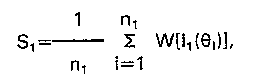
arc 1, are each first processed for spurious noise contributions, weighted by operating on each with some functional operator, W(l1)' and then averaged; similarly forarc 2. - On the foregoing basis, two weighted intensity values may be generated from each measurement. Thus if the n1 values measured about θ1 be 11 (θi) (i=1 to n1) we form the average
- Referring to Figure 2, in place of the two detector arrays of
elements 6, two bundles ofoptical fibers 11 may be used to transmit the scattered light to theface plate 12 of a multianode microchannel array (MAMA)tube 22 of the type manufactured by Litton Industries and Ball Aerospace Systems Division and as discussed in our co-pending Patent Application No. 83303602.3. - The MAMA tube may be thought of as a set of photomultipliers operating in parallel. Below each attached
fiber element 11 corresponding to a particular angular location is theface plate 12, providing a photocathode surface, followed by a set of microchannels in amicrochannel plate 13. Photoelectrons produced in a local region of thephotocathode surface 12 are accelerated through themicrochannel plate 13 and yield a burst of electrons at a corresponding pixel element in apixel array 14. In general, a fiber element will subtend a region of the photocathode corresponding approximately to the area of a pixel element. Of the order of 30 to 100 microchannels will supply electrons to each pixel. The bursts of electrons impinging on each pixel, or anode, are transmitted bymeans 15 to amplifying and countingelectronics 16 which increments a RAM counter/word residing in a computeraccessible RAM 17. Each pixel provides the counts for its own RAM word. By means of acentral processor 18, the counters may be read and zeroed under program control. - The pixel counting rates, which should be directly proportional to the incident photon flux through the corresponding fiber element, usually remain linear up to a few megahertz. If the photon flux from a particular fiber element be too great, the corresponding pixel elements would saturate and result in non-linear counting rate, thereby distorting the actual intensity value initiating that particular rate. By varying the cross-section of the
individual fibers 11 or by varying masks 8 to which they are attached bymeans 9, the maximum photon flux incident on each fiber element per second may be varied. Because the light scattered by particles becomes more pronounced in the forward scattering direction, as the particles increase in size relative to the wavelength of the incident radiation, the masks 8 corresponding to the forward detector set 1 would, in the preferred embodiment of this invention, have apertures of smaller cross-section than those of the corresponding largerangle detector set 2. After counting is completed, the recorded rates may be corrected for the mask attenuated values. Since photons scattered by thetarget particles 4 should not reflect from the detecting fiber elements, as these reflections could cause additional noise in the system and degrade the absolute differences derived between forward and backward intensities, the face of eachfiber element 10 is slightly bevelled, in the preferred embodiment of this invention, so as substantially to prevent such reflected light from exiting through the mask element 8. - In the preferred embodiment of this invention, the counts of each pixel may be limited to fixed time periods under program control via the
central processing unit 18. For some types of measurements, on which basis a particular microparticle ensemble is to be characterized or compared to a reference system, the time periods could be quite long, perhaps corresponding to several seconds, or even minutes. For other types of measurements whereby instantaneous values need be obtained so as to derive effective scattered radiation rates at the two angular positions θ↑ and 02, the. time periods might be chosen as small fractions of a second, depending upon the resolution required. It is important to stress, however, that the intensity or rate values derived from the measurements at the two distinct angular positions 01 and 82 be as free from spurious noise as possible. Between counts it will be necessary for theCPU 18 to analyse the data at each of the satellite angular locations to detect and surpress values whose origins did not correspond to the particular particle ensemble being studied. For example, were one to monitor the reaction rate between interacting antigen-antibody complexes, some contributions to the recorded signals would be expected to arise because of cellular remnants in the serum aliquot used in the experiment, or even dust or debris that may have inadvertently been introduced into the sample. A significant feature of the angular arrays surrounding the two principal angular locations should now be apparent: by examining the scattered light variations at many angles with respect to the incident beam direction, contributions from specular reflections, as would be expected from large pieces of debris, may easily be followed. During time periods in which such anomalous scattering events are taking place, the CPU system of the preferred embodiment should be programmed to suppress the recorded values completely, replacing them with values derived by interpolation of noise-free results spanning the noise events in time. - Although the preferred embodiment of the invention has indicated the use of a compact MAMA tube, with associated electronics, for the initial detection of the angular scattering data, other detection schemes may be equally well adapted as would be evident to those skilled in the art of measuring scattered light intensities. These would include, but not be limited to, sets of photodiodes with appropriate amplifiers as well as groups of photomultipliers, vidicons, and digicon units such as manufactured by SAI, Inc.
- It is important to emphasise that the present invention is not a simple variation of a nephelometer, nor is the measurement a variation of a dissymmetry measurement such as performed by physical chemists concerned with the determination of molecular weights or particles sizes. Likewise, it is not similar to the dual angle device of Sloan as discussed in his US patent No. 2816479. As regards a conventional nephelometer, such an instrument makes a measurement of the scattered light intensity at a fixed angle or collects the total amount of light scattered into a single detector structure spanning a broad angular range. A dissymmetry measurement, on the other hand, usually consists of making a measurement of the ratio of light scattered at 45° to light scattered at 135°. For particles very small compared to the wavelength of the incident light, this ratio is unity. As the particle size increases, the ratio increases thus signifying the presence of larger particles. Many different size distributions, however, can yield identical dissymmetry ratios and for the case of monodisperse particles, once their size becomes comparable to the wavelength of the incident light, the ratio may again be less than unit when sharp scattering minima occur at 45°. By measuring the scattered intensity ratio at two angles near the forward direction, Sloan's device was useful for detecting the presence of particles and obtaining a coarse measurement of their average size.
- The present embodiment makes two absolute measurements of the scattered intensity at two angles: one in the forward direction and one at a larger angle (greater than 90°), as has been previously described. Since each of these measurements has been averaged over a range of angles subtended about the chosen angles, and since the values at each angle have been processed digitally to remove as many detected spurious data as possible before averaging, the resulting two values will be of such a precise nature that subsequent measurements of the same particulate ensemble under the same physical conditions will yield the same values. Thus these two values referred to the two values of a fixed standard such as a known concentration of polystyrene latex particles as manufactured by Dow Chemical Co., or to some absolute photometric standard, may be used for the absolute characterization of the light scattering ensemble or as a simple means to compare one ensemble with another, or as a means to monitor the response of a microparticle ensemble to its environment, with the aforementioned two values being measured before and after exposure to the environment. Naturally, the means of combining the detected angular data to yield these two averaged values may be of many forms, as has been described previously, such as a multiplicative weighting before averaging, forming the logarithms of each processed value before averaging, etc. The particular operation performed on the processed angular scattering data before averaging would naturally depend on the types of particles being considered. In the preferred embodiment of this invention, the instrument performing these measurements would be under program control and would yield intensity values at the two angles based on one or more selected averaging procedures. Indeed, several pairs of output values could be generated following each measurement, one pair for each averaging procedure employed. Thus a given particle ensemble could be characterized by several pairs of numbers, each pair of which is based on a different averaging technique.
- As an example of the processing of the recorded data to yield the two scattering values for a particular ensemble of particles, consider that measurements are made at each of the n1 angular locations surrounding angle θ1 and each of the n2 angular locations surrounding. angle θ2. Note that n1 and n2 need not be equal, nor need the spacings between the angular locations be equidistant. At a particular angle θi1 (i=1 to n,), let N successive measurements be made of the scattered intensity li1 within a time period such that the physical properties of the ensemble have not been affected by their environment during this time. Calculate the average valu
e l i1 and its associated standard deviation σi1. Discard any value exceeding, say, two standard deviations and recalculate the average value l i1 . Repeat this procedure until all remaining values lie within one standard deviation. Repeat for all the n1 angles θi1, and the n2 angles θ12' all intensities measured within the time. - Now consider some weighting operator, W, such as logarithmic operation and/or an arithmetic scaling factor fi, and calculate W
[li1 ]fi, (i=1 to n,) and W[l i2 ]fi, (i=1 to n2). The average values associated with angle θ1 and 82, respectively, would then be given by


- For certain environments, one wishes to compare the response, Re, of a control ensemble of particles which do not experience the environment with the response, RT, of a test ensemble exposed to the environmental stress. Referring to the example of a response given by Eq. (5), one would generate it for the control ensemble to yield Re and then for the test ensemble to yield RT. There are two important examples of the utility of this type of determination.
- First consider the measurement of the response of an ensemble of bacterial cells, isolated from an infection site, to a particular antimicrobial agent. Two identical aliquots of the bacterial cells are placed in separate identical curvettes containing some type of growth medium such as Columbia broth. To one is added a certain concentration of the antimicrobial under consideration; to the other is added an equal fluid volume, absent the antimicrobial. Both final solutions have the same initial bacterial concentrations and at time t=0, the quantities V1 and V2 are identical since the set li1 (i=1 to n1) and li2 (i=1 to n2) are identical for both solutions. Any departures from equality at t=0 immediately may be used to warn of a misprepared sample or malfunctioning detection means. After incubation for a period of time t, measurements of V1 and V2 for the control sample will differ from measurements of V1 and V2 for the test sample, if the antimicrobial has had an effect. In this case, the responses Re and RT will be different. These responses may now be used to quantitate the minimum inhibotory concentration, or simply MIC, by calculating a functional quantity, M(Re, RT, D) where D is the concentration of the antimicrobial yielding this difference between the responses Re and RT. For example, the function M yielding an MIC value might be simply of the form:

- Consider next the case where viable bacterial cells, for example, are to be used in a bioassay test for the presence of some type of toxicant in a solution, such as water. To a control sample of an equivalent solution known a priorito contain no toxicant is added an aliquot of the bacteria. An equal aliquot of cells is added to the test solution. If the latter contain a toxicant to which the test bacteria are sensitive, then after incubation, the measured response to the sample solution will differ from the response to the control solution. This difference represents therefore an indication that the test solution contains a toxicant or other substance that affects the test bacteria, i.e. the method yield a bioassay of the sample solution for the range and levels of toxicants to which the test organisms are responsive. Similar examples of such bioassay procedures would include, but not be limited to, the bioassay of various food exudate for the presence of residues such as herbicides, antimicrobials, pesticides, mycotoxins, and heavy metals.
- The characterization of particle ensembles by measurement of the quantities V1 and V2 or D1 and D2 permits, under suitable conditions, the detection of specific particle ensembles for which such characterization parameters are unique. For example, consider the detection of bacteria in urine, a potentially life threatening infection referred to as bactiurea. With the exception of some white and, possibly, red blood cells, large crystalline precipitates, and other agglomerates, urine is sterile and generally free of particles. By coarse filtering, all of the larger particles, say greater in diameter than 3 pm, may easily be removed. If the remaining filtrate contains bacteria at a sufficient concentration to scatter a sufficient fraction of the total incident light scattered, then the presumptive detection of such cells may be made if the data V, and V2 fall in certain proscribed ranges. Confirmation of the presence of bacteria or yeasts and quantization of the number of densities present may be implemented by measuring a response function of the type of Eq. (5) over various periods of time, while monitoring values of V1t and V2t to further confirm that these values do indeed lie within ranges characteristic of bacteria or yeasts.
- It will be appreciated that any toxicants or other chemical agents to which a strain of bacteria may be found sensitive/responsive may be detected and assayed by the above described procedures.
- While there has hereinbefore been presented what are at present considered to be the preferred embodiment and method, it will be apparent to those of ordinary skill in the art that many modifications and variations may be made therefore without departing from the true spirit and scope of the invention as claimed. All such variations and modifications, therefore, are considered to be a part of the invention.
Claims (36)

Applications Claiming Priority (2)
| Application Number | Priority Date | Filing Date | Title |
|---|---|---|---|
| US403340 | 1982-07-20 | ||
| US06/403,340 US4541719A (en) | 1982-07-20 | 1982-07-20 | Method and apparatus for characterizing microparticles and measuring their response to their environment |
Publications (2)
| Publication Number | Publication Date |
|---|---|
| EP0102726A1 EP0102726A1 (en) | 1984-03-14 |
| EP0102726B1 true EP0102726B1 (en) | 1988-06-08 |
Family
ID=23595422
Family Applications (1)
| Application Number | Title | Priority Date | Filing Date |
|---|---|---|---|
| EP83304206A Expired EP0102726B1 (en) | 1982-07-20 | 1983-07-20 | Method and apparatus for characterizing microparticles or measuring their response to their environment |
Country Status (3)
| Country | Link |
|---|---|
| US (1) | US4541719A (en) |
| EP (1) | EP0102726B1 (en) |
| DE (1) | DE3377013D1 (en) |
Cited By (1)
| Publication number | Priority date | Publication date | Assignee | Title |
|---|---|---|---|---|
| US8236168B2 (en) | 2009-10-13 | 2012-08-07 | Exxonmobil Research And Engineering Company | Onset haze measurement apparatus and procedure |
Families Citing this family (58)
| Publication number | Priority date | Publication date | Assignee | Title |
|---|---|---|---|---|
| US4661913A (en) * | 1984-09-11 | 1987-04-28 | Becton, Dickinson And Company | Apparatus and method for the detection and classification of articles using flow cytometry techniques |
| US4907884A (en) * | 1984-11-15 | 1990-03-13 | Wyatt Technology Corporation | Sample cell monitoring system |
| US4616927A (en) * | 1984-11-15 | 1986-10-14 | Wyatt Technology Corporation | Sample cell for light scattering measurements |
| US4702598A (en) * | 1985-02-25 | 1987-10-27 | Research Corporation | Flow cytometer |
| US5082790A (en) * | 1985-12-23 | 1992-01-21 | Beckman Instruments, Inc. | Apparatus and method for dynamic blanking of non-specific light scattering during rate nephelometric reactions |
| US4890920A (en) * | 1986-02-12 | 1990-01-02 | Combustion Engineering, Inc. | In situ particle size measuring device |
| EP0449820A1 (en) * | 1988-04-18 | 1991-10-09 | Technical Assessment Systems, Inc. | Radiation/microbe bioassay |
| DE3813718A1 (en) * | 1988-04-22 | 1989-11-02 | Max Planck Gesellschaft | Multi-angle light scattering |
| US4991971A (en) * | 1989-02-13 | 1991-02-12 | United Technologies Corporation | Fiber optic scatterometer for measuring optical surface roughness |
| US5104221A (en) * | 1989-03-03 | 1992-04-14 | Coulter Electronics Of New England, Inc. | Particle size analysis utilizing polarization intensity differential scattering |
| US5056918A (en) * | 1989-03-03 | 1991-10-15 | Coulter Electronics Of New England, Inc. | Method and apparatus for particle size analysis |
| US4953978A (en) * | 1989-03-03 | 1990-09-04 | Coulter Electronics Of New England, Inc. | Particle size analysis utilizing polarization intensity differential scattering |
| JP2715604B2 (en) * | 1989-12-18 | 1998-02-18 | 株式会社島津製作所 | Laser diffraction / scattering particle size distribution analyzer |
| DE69129260T2 (en) * | 1990-11-03 | 1998-11-19 | Horiba Ltd | Device for measuring the particle size distribution |
| CA2092373A1 (en) * | 1992-04-24 | 1993-10-25 | Klaus W. Berndt | Methods and apparatus for detecting biological activities in a specimen |
| GB9313052D0 (en) * | 1993-06-24 | 1993-08-11 | Mini Agriculture & Fisheries | Detection of microbial growth |
| US5475235A (en) * | 1993-08-09 | 1995-12-12 | Wyatt Technoloy Corporation | Control of laser light power output for use in light scattering instruments by inducing mode hopping and averaging result |
| AU6385496A (en) * | 1995-06-13 | 1997-01-09 | University Of South Florida | Multi-angle, multiwavelength particle characterization syste m and method |
| US5701176A (en) * | 1995-07-28 | 1997-12-23 | Precision Detectors, Inc. | High temperature light scattering measurement device comprising a rigid extension tube |
| US5751423A (en) * | 1996-12-06 | 1998-05-12 | United Sciences, Inc. | Opacity and forward scattering monitor using beam-steered solid-state light source |
| US5831730A (en) * | 1996-12-06 | 1998-11-03 | United Sciences, Inc. | Method for monitoring particulates using beam-steered solid-state light source |
| DE19717749A1 (en) * | 1997-04-21 | 1998-10-22 | Fraunhofer Ges Forschung | Method and device for the quantitative and qualitative on-line differentiation of biotic and abiotic particles |
| US5932813A (en) * | 1997-10-07 | 1999-08-03 | North Carolina State University | Method and system for residence time measurement of simulated food particles in continuous thermal food processing and simulated food particles for use in same |
| US6055052A (en) * | 1998-01-26 | 2000-04-25 | Mie Corporation | System for, and method of, monitoring airborne particulate, including particulate of the PM2.5 class |
| GB9818348D0 (en) * | 1998-08-22 | 1998-10-14 | Malvern Instr Ltd | Improvements relating to the measurement of particle size distribution |
| US6795183B2 (en) | 1999-02-19 | 2004-09-21 | Metron Instruments, Inc. | Measurement systems and methods for determining component particle concentrations in a liquid |
| US6407813B1 (en) | 1999-02-19 | 2002-06-18 | On-Line Instrumentation, Inc. | Measurement systems and methods for determining component particle concentrations in a liquid |
| US6507400B1 (en) | 1999-02-27 | 2003-01-14 | Mwi, Inc. | Optical system for multi-part differential particle discrimination and an apparatus using the same |
| US6251624B1 (en) | 1999-03-12 | 2001-06-26 | Akzo Nobel N.V. | Apparatus and method for detecting, quantifying and characterizing microorganisms |
| US6942989B2 (en) | 1999-05-03 | 2005-09-13 | Icf Technologies, Inc. | Methods, compositions and kits for biological indicator of sterilization |
| US20040106167A1 (en) * | 1999-05-03 | 2004-06-03 | Icf Technologies, Inc. | Methods for evaluating sterilization procedures using a biological indicator |
| US7326562B2 (en) * | 1999-05-03 | 2008-02-05 | Icf Technologies, Inc. | Biological indicator system to detect effectiveness of sterilization |
| US6480276B1 (en) | 1999-07-13 | 2002-11-12 | Clemson University | Enhanced photon-migration methods for particle sizing in concentrated suspensions |
| WO2001029534A1 (en) | 1999-10-15 | 2001-04-26 | The Administrators Of The Tulane Educational Fund | Device for and method of simultaneously measuring light scatter from multiple liquid samples |
| US6177993B1 (en) * | 1999-12-07 | 2001-01-23 | The Regents Of The University Of California | Inspection of lithographic mask blanks for defects |
| US6646742B1 (en) | 2000-02-19 | 2003-11-11 | Mwi, Inc. | Optical device and method for multi-angle laser light scatter |
| DE10036860A1 (en) * | 2000-07-28 | 2002-02-07 | Basf Ag | Method and device for determining physical collective parameters of particles in gases |
| GB2371358A (en) * | 2001-01-22 | 2002-07-24 | Optokem Ltd | Light scattering particle characterisation apparatus and detection means |
| US20040043433A1 (en) * | 2002-01-25 | 2004-03-04 | Satish Deshpande | Light scatering determination of treatment potencies |
| WO2002077748A2 (en) * | 2001-02-01 | 2002-10-03 | Carrick, Bruce | Light scatteringdetermination of treatment potencies |
| US7404929B2 (en) * | 2002-01-18 | 2008-07-29 | Newton Laboratories, Inc. | Spectroscopic diagnostic methods and system based on scattering of polarized light |
| JP2005515472A (en) * | 2002-01-18 | 2005-05-26 | ニユートン・ラボラトリーズ・インコーポレーテツド | Spectroscopic diagnosis method and system |
| US6819421B1 (en) * | 2003-04-11 | 2004-11-16 | Point Source Technologies, Llc | Detection of new species of particles |
| US7411680B2 (en) * | 2003-07-19 | 2008-08-12 | Digital Bio Technology | Device for counting micro particles |
| US6774994B1 (en) * | 2003-08-13 | 2004-08-10 | Wyatt Technology Corporation | Method and apparatus for determining absolute number densities of particles in suspension |
| US7365835B2 (en) * | 2003-12-02 | 2008-04-29 | California Institute Of Technology | Dark-field laser-scattering microscope for analyzing single macromolecules |
| US7671988B2 (en) * | 2004-02-18 | 2010-03-02 | American Ecotech Llc | Detection of particles |
| US7502110B2 (en) * | 2004-07-21 | 2009-03-10 | Lighthouse Worldwide Solutions, Inc | Design for particle sensor system |
| JP2008039539A (en) * | 2006-08-04 | 2008-02-21 | Shimadzu Corp | Light scattering detector |
| CN101055241B (en) * | 2007-05-10 | 2010-08-04 | 中国科学院安徽光学精密机械研究所 | Multiple-passage dispersion reverse deduction microgranule tri-dimensional shape detector and detection method |
| CN101082562B (en) * | 2007-06-28 | 2010-12-29 | 中国科学院安徽光学精密机械研究所 | Device for monitoring micro-particles shapes and dispersion based on image |
| US20100189338A1 (en) * | 2008-04-09 | 2010-07-29 | Nexcelom Bioscience | Systems and methods for counting cells and biomolecules |
| US7982875B2 (en) * | 2009-06-15 | 2011-07-19 | Wyatt Technology Corporation | Method and apparatus for measuring the scattered light signals from a liquid sample |
| WO2011004781A1 (en) * | 2009-07-10 | 2011-01-13 | 株式会社日立ハイテクノロジーズ | Automatic analyzer |
| US20110223586A1 (en) * | 2010-03-11 | 2011-09-15 | David Karabinus | Optical particle characterization system |
| US9377481B1 (en) * | 2010-06-16 | 2016-06-28 | The United States Of America As Represented By The Administrator Of National Aeronautics And Space Administration | Multi-parameter scattering sensor and methods |
| DE102015217700B3 (en) | 2015-09-16 | 2016-12-15 | Fraunhofer-Gesellschaft zur Förderung der angewandten Forschung e.V. | Method for determining the mean radius of gyration of particles with a size of less than or equal to 200 nm in a suspension and apparatus for carrying out the method |
| WO2018031820A1 (en) * | 2016-08-10 | 2018-02-15 | Hannu Harjunmaa | Nephelometer |
Family Cites Families (8)
| Publication number | Priority date | Publication date | Assignee | Title |
|---|---|---|---|---|
| US3730842A (en) * | 1970-05-04 | 1973-05-01 | Science Spectrum | Process for determining bacterial drug sensitivity |
| GB1389247A (en) * | 1972-03-03 | 1975-04-03 | Dittrich W | Device for counting and characterising small particles |
| US4314347A (en) * | 1973-01-22 | 1982-02-02 | Texaco Inc. | Seismic signal processing machine and method for noise removal |
| US3928140A (en) * | 1974-05-10 | 1975-12-23 | Philip J Wyatt | Apparatus and process for testing microparticle response to its environment |
| US4070113A (en) * | 1976-05-05 | 1978-01-24 | California Institute Of Technology | Coherent optics blood cell classification system |
| US4174952A (en) * | 1978-01-23 | 1979-11-20 | Massachusetts Institute Of Technology | Immunoassay by light scattering intensity anisotropy measurements |
| US4204837A (en) * | 1978-03-14 | 1980-05-27 | Beckman Instruments, Inc. | Method of rate immunonephelometric analysis |
| JPS5925460B2 (en) * | 1978-05-19 | 1984-06-18 | 株式会社日立製作所 | Nephelometric immunoassay method and device |
-
1982
- 1982-07-20 US US06/403,340 patent/US4541719A/en not_active Expired - Lifetime
-
1983
- 1983-07-20 DE DE8383304206T patent/DE3377013D1/en not_active Expired
- 1983-07-20 EP EP83304206A patent/EP0102726B1/en not_active Expired
Cited By (1)
| Publication number | Priority date | Publication date | Assignee | Title |
|---|---|---|---|---|
| US8236168B2 (en) | 2009-10-13 | 2012-08-07 | Exxonmobil Research And Engineering Company | Onset haze measurement apparatus and procedure |
Also Published As
| Publication number | Publication date |
|---|---|
| DE3377013D1 (en) | 1988-07-14 |
| EP0102726A1 (en) | 1984-03-14 |
| US4541719A (en) | 1985-09-17 |
Similar Documents
| Publication | Publication Date | Title |
|---|---|---|
| EP0102726B1 (en) | Method and apparatus for characterizing microparticles or measuring their response to their environment | |
| US5194909A (en) | Apparatus and method for measuring volume and hemoglobin concentration of red blood cells | |
| JP2505873B2 (en) | Particle analyzer with scattered light | |
| EP0140616B1 (en) | Method and apparatus for determining the volume and index of refraction of particles | |
| US5502561A (en) | Characterization of particles by modulated dynamic light scattering | |
| JP3479044B2 (en) | Chemical mechanical planarization (CMP) slurry quality control process and particle size distribution measurement system | |
| EP0098095B1 (en) | A process and apparatus for identifying or characterizing small particles | |
| US6421121B1 (en) | Method and apparatus for rapid particle identification utilizing scattered light histograms | |
| RU97118363A (en) | METHOD AND DEVICE FOR QUANTITATIVE DETERMINATION OF PARTICLES IN LIQUID MEDIA | |
| GB2432660A (en) | System for counting bacteria and determining their susceptibility to antibiotics | |
| DE10008517A1 (en) | Optical system for determining the concentration of a turbid liquid sample, e.g. a cell or bacterial culture, comprises a sample chamber with light paths, each with a light emitter and photoreceptor on opposite sides of the chamber | |
| JPS61153546A (en) | Particle analyzer | |
| CA1081497A (en) | System for rate immunonephelometric analysis | |
| US6104491A (en) | System for determining small particle size distribution in high particle concentrations | |
| Gravati Jr | Real time measurement of the size distribution of particulate matter by a light scattering method | |
| Eisert et al. | Simple flow microphotometer for rapid cell population analysis | |
| US4375334A (en) | Nephelometer | |
| JP2000187037A (en) | Sample analyzing device provided with function of controlling accuracy | |
| Bremel et al. | Estimating somatic cells in milk samples by the membrane-filter-DNA procedure | |
| GB2068544A (en) | Methods and apparatus for testing biological cells | |
| Gray et al. | A new method for cell volume measurement based on volume exclusion of a fluorescent dye | |
| RU2672534C1 (en) | Optical method of measurement of concentration and morphology of particles in wide range of turbidity and device for its implementation | |
| Mestre | A precision photometer for the study of suspensions of bacteria and other microorganisms | |
| JPH03122550A (en) | Method and apparatus of measuring grain | |
| Shimizu et al. | Scattering pattern analysis of bacteria |
Legal Events
| Date | Code | Title | Description |
|---|---|---|---|
| PUAI | Public reference made under article 153(3) epc to a published international application that has entered the european phase |
Free format text: ORIGINAL CODE: 0009012 |
|
| AK | Designated contracting states |
Designated state(s): DE FR GB IT SE |
|
| 17P | Request for examination filed |
Effective date: 19840914 |
|
| RAP1 | Party data changed (applicant data changed or rights of an application transferred) |
Owner name: WYATT TECHNOLOGY CORPORATION |
|
| RAP1 | Party data changed (applicant data changed or rights of an application transferred) |
Owner name: WYATT TECHNOLOGY CORPORATION |
|
| GRAA | (expected) grant |
Free format text: ORIGINAL CODE: 0009210 |
|
| AK | Designated contracting states |
Kind code of ref document: B1 Designated state(s): DE FR GB IT SE |
|
| PG25 | Lapsed in a contracting state [announced via postgrant information from national office to epo] |
Ref country code: IT Free format text: LAPSE BECAUSE OF FAILURE TO SUBMIT A TRANSLATION OF THE DESCRIPTION OR TO PAY THE FEE WITHIN THE PRESCRIBED TIME-LIMIT;WARNING: LAPSES OF ITALIAN PATENTS WITH EFFECTIVE DATE BEFORE 2007 MAY HAVE OCCURRED AT ANY TIME BEFORE 2007. THE CORRECT EFFECTIVE DATE MAY BE DIFFERENT FROM THE ONE RECORDED. Effective date: 19880608 |
|
| PG25 | Lapsed in a contracting state [announced via postgrant information from national office to epo] |
Ref country code: SE Effective date: 19880630 |
|
| REF | Corresponds to: |
Ref document number: 3377013 Country of ref document: DE Date of ref document: 19880714 |
|
| ET | Fr: translation filed | ||
| PLBE | No opposition filed within time limit |
Free format text: ORIGINAL CODE: 0009261 |
|
| STAA | Information on the status of an ep patent application or granted ep patent |
Free format text: STATUS: NO OPPOSITION FILED WITHIN TIME LIMIT |
|
| 26N | No opposition filed | ||
| REG | Reference to a national code |
Ref country code: GB Ref legal event code: IF02 |
|
| PGFP | Annual fee paid to national office [announced via postgrant information from national office to epo] |
Ref country code: GB Payment date: 20020517 Year of fee payment: 20 |
|
| PGFP | Annual fee paid to national office [announced via postgrant information from national office to epo] |
Ref country code: FR Payment date: 20020718 Year of fee payment: 20 |
|
| PGFP | Annual fee paid to national office [announced via postgrant information from national office to epo] |
Ref country code: DE Payment date: 20020729 Year of fee payment: 20 |
|
| PG25 | Lapsed in a contracting state [announced via postgrant information from national office to epo] |
Ref country code: GB Free format text: LAPSE BECAUSE OF EXPIRATION OF PROTECTION Effective date: 20030719 |
|
| REG | Reference to a national code |
Ref country code: GB Ref legal event code: PE20 |