EP0102457B1 - Device for measuring of concentration - Google Patents
Device for measuring of concentration Download PDFInfo
- Publication number
- EP0102457B1 EP0102457B1 EP19830105530 EP83105530A EP0102457B1 EP 0102457 B1 EP0102457 B1 EP 0102457B1 EP 19830105530 EP19830105530 EP 19830105530 EP 83105530 A EP83105530 A EP 83105530A EP 0102457 B1 EP0102457 B1 EP 0102457B1
- Authority
- EP
- European Patent Office
- Prior art keywords
- valve part
- channel
- inlet channel
- complex medium
- movable valve
- Prior art date
- Legal status (The legal status is an assumption and is not a legal conclusion. Google has not performed a legal analysis and makes no representation as to the accuracy of the status listed.)
- Expired
Links
- 238000004891 communication Methods 0.000 claims abstract description 24
- 239000012482 calibration solution Substances 0.000 claims abstract description 20
- 150000003384 small molecules Chemical class 0.000 claims abstract description 14
- 238000005259 measurement Methods 0.000 claims abstract description 12
- 102000004190 Enzymes Human genes 0.000 claims abstract description 5
- 108090000790 Enzymes Proteins 0.000 claims abstract description 5
- 239000003146 anticoagulant agent Substances 0.000 claims description 21
- 229940127219 anticoagulant drug Drugs 0.000 claims description 21
- 238000000502 dialysis Methods 0.000 claims description 4
- 239000006193 liquid solution Substances 0.000 claims description 2
- 238000011144 upstream manufacturing Methods 0.000 claims description 2
- 239000008280 blood Substances 0.000 description 13
- 210000004369 blood Anatomy 0.000 description 13
- 238000013208 measuring procedure Methods 0.000 description 7
- 239000007788 liquid Substances 0.000 description 5
- WQZGKKKJIJFFOK-GASJEMHNSA-N Glucose Natural products OC[C@H]1OC(O)[C@H](O)[C@@H](O)[C@@H]1O WQZGKKKJIJFFOK-GASJEMHNSA-N 0.000 description 4
- 239000008103 glucose Substances 0.000 description 4
- 238000005086 pumping Methods 0.000 description 2
- 239000002699 waste material Substances 0.000 description 2
- BWOUGSIOJMUVHK-UHFFFAOYSA-N CC1[IH]CCC1 Chemical compound CC1[IH]CCC1 BWOUGSIOJMUVHK-UHFFFAOYSA-N 0.000 description 1
- 0 CC=*1C=CC*1 Chemical compound CC=*1C=CC*1 0.000 description 1
- 241001631457 Cannula Species 0.000 description 1
- 230000017531 blood circulation Effects 0.000 description 1
- 230000015271 coagulation Effects 0.000 description 1
- 238000005345 coagulation Methods 0.000 description 1
- 150000001875 compounds Chemical class 0.000 description 1
- 238000012258 culturing Methods 0.000 description 1
- 230000002906 microbiologic effect Effects 0.000 description 1
- 230000037361 pathway Effects 0.000 description 1
- 239000000243 solution Substances 0.000 description 1
- 239000012086 standard solution Substances 0.000 description 1
- 230000009897 systematic effect Effects 0.000 description 1
Images


Classifications
-
- C—CHEMISTRY; METALLURGY
- C12—BIOCHEMISTRY; BEER; SPIRITS; WINE; VINEGAR; MICROBIOLOGY; ENZYMOLOGY; MUTATION OR GENETIC ENGINEERING
- C12M—APPARATUS FOR ENZYMOLOGY OR MICROBIOLOGY; APPARATUS FOR CULTURING MICROORGANISMS FOR PRODUCING BIOMASS, FOR GROWING CELLS OR FOR OBTAINING FERMENTATION OR METABOLIC PRODUCTS, i.e. BIOREACTORS OR FERMENTERS
- C12M41/00—Means for regulation, monitoring, measurement or control, e.g. flow regulation
- C12M41/30—Means for regulation, monitoring, measurement or control, e.g. flow regulation of concentration
- C12M41/32—Means for regulation, monitoring, measurement or control, e.g. flow regulation of concentration of substances in solution
-
- Y—GENERAL TAGGING OF NEW TECHNOLOGICAL DEVELOPMENTS; GENERAL TAGGING OF CROSS-SECTIONAL TECHNOLOGIES SPANNING OVER SEVERAL SECTIONS OF THE IPC; TECHNICAL SUBJECTS COVERED BY FORMER USPC CROSS-REFERENCE ART COLLECTIONS [XRACs] AND DIGESTS
- Y10—TECHNICAL SUBJECTS COVERED BY FORMER USPC
- Y10T—TECHNICAL SUBJECTS COVERED BY FORMER US CLASSIFICATION
- Y10T137/00—Fluid handling
- Y10T137/8593—Systems
- Y10T137/86493—Multi-way valve unit
- Y10T137/86863—Rotary valve unit
Definitions
- This invention relates to a device for measuring of the concentration of a low molecular weight compound in a complex medium taken from a source of such a medium.
- the device comprises a dialyzer, possibly an enzyme reactor, and a measuring unit in connection with each other through a channel system, said measuring unit measures the concentration of the low molecular weight compound at the dialysate side of the dialyzer.
- the invention is relating to a device of the disclosed kind for measuring of glucose in blood of for example a patient.
- a drawback with this known measuring procedure is that calibration is performable only at the beginning of each measurement. This means that after an initial calibration one is left to rely upon this calibration result during the whole concentration measurement. This is of course insufficient, since the measuring unit (particularly if this is a measuring electrode) easily can give rise to systematic deviations during the measurement depending on for example temperature disturbances or the like. It would be desirable to be able to perform calibration also during the measuring procedure in order to achieve a check of the accuracy of the measuring unit and thereby a safer measuring result.
- An object of the invention is therefore to meet this desire and to provide a device by means of which it is possible to calibrate the measuring unit also during the measuring procedure.
- a device for measuring of the concentration of a low molecular weight compound in a complex medium taken from a source of such a medium which comprises a dialyzer, possibly an enzyme reactor, and a measuring unit in connection with each other through a channel system, said measuring unit measures the concentration of the low molecular weight compound at the dialysate side of the dialyzer.
- the device is characterized by comprising a valving means in a position upstream of the dialyzer which is adapted to alternatingly direct the complex medium and a calibration solution, respectively, through the other side of the dialyzer, whereby it is possible to calibrate the measuring unit during the concentration measurement without disconnecting the device from said source of the complex medium or the outlet for the consumed dialysis liquid and calibration solution.
- the device according to the present invention comprises preferably a dialyzer 1, an enzyme reactor 2, a measuring unit 3, a temperature sensor 4, a deaerator 5, and a flow changing device 6.
- a dialyzer 1 As is shown in Fig. 1 the device according to the present invention comprises preferably a dialyzer 1, an enzyme reactor 2, a measuring unit 3, a temperature sensor 4, a deaerator 5, and a flow changing device 6.
- a temperature sensor 4 As is shown in Fig. 1 the device according to the present invention comprises preferably a dialyzer 1, an enzyme reactor 2, a measuring unit 3, a temperature sensor 4, a deaerator 5, and a flow changing device 6.
- said elements are preferably arranged on the top side of a stack of plates 7, 8, 9 and in communication with each other through a channel system.
- Example of the preferred channel system may be the channel system as described in our EP-A-0 102 458 published on 14.3.84. Briefly, this channel system is composed of channels being formed between the stacked plates and a part of which is shown in Fig. 1 in the form of tubes 10, 11, 12 which are arranged over a pump hole P through the plates to thereby provide a means for pumping the individual liquids in the channel system.
- the present device also includes a valving means (designated 1 in Fig. 1) which will be described in more detail in the following with reference to Figs. 2-6.
- the valving means comprises preferably a valve piece 13, which is movable between two positions, and a stationary of fixed part 14, whereby the movable valve part 13 with its one end 13a conveniently is releasably attached to a corresponding end 14a of the fixed valve part 14.
- the movable valve part 13 comprises an openable and closable inlet channel 15 for the complex medium, for example blood, which is adapted to be withdrawn from a patient by means of a cannula 16 and tube 17.
- the inlet channel 15 is in turn connectable to the dialyzer 1 via a corresponding outlet channel 18 in the fixed valve part 14 and the not shown channel system between the plates 10, 11, 12.
- the fixed valve part 14 comprises an inlet channel 19 for calibration solution, whereby the inlet channel 19 is directly connectable to the outlet channel 18 via a groove 20 formed in the end 13a of the movable valve part 13, as will be described in the following.
- the fixed valve part 14 preferably comprises an inlet channel 21 for anticoagulant, whereby this channel is directly connectable to the outlet channel 18 via said groove 20 of the movable valve part 13, and indirectly connectable to the outlet channel 18 via a corresponding channel 22 of the movable valve part 13 and a tube 23 which via a cannula 16 is in communication with the tube 17 forthe complex medium and consequently, the inlet channel 15 in the movable valve part 13, as mentioned above.
- the respective source for calibration solution and anticoagulant may for example be the container which is described in the Swedish Patent Application No. 8104146-7 Published on 4.1.83, and which can be in communication with the channel system in the plates 7, 8, 9 in the manner as described in our EP-A-0 102 458.
- this container is provided with a level marking of the kind as described in the Swedish Patent Application No. 8104147-7, published 4.1.83.
- Fig. 1 you may furthermore see an inlet 25 for the calibration solution connected to the channel 19 for said solution, an inlet 26 for the anticoagulant connected to the inlet channel 21 for said anticoagulant, an inlet 27 for the dialysis liquid which is being pumped to the dialyzer by means of the pumping segment 10 and an outlet 28 for the consumed dialysis liquid, calibration solution and complex medium.
- the valving means is set, preferably by means of an arm 24, in the position as shown in Figs. 2 and 3.
- the inlet channel 19 for calibration solution in the fixed valve part 14 is in communication with the groove 20 at 20a and via this groove at 20b in communication with the outlet channel 18 in the fixed valve part 14 which, as described, is in communication with the dialyzer 1 via the channel system between the plates 7, 8, 9.
- the inlet channel 21 for anticoagulant in the fixed valve part 14 is in communication with the groove 20 at 20c and via this groove at 20b in communication with the outlet channel 18. Furthermore, it can be seen from Figs. 2 and 3 that the communication between the inlet channel 15 for the complex medium in the movable valve part 13 and the outlet channel 18 is interrupted. The communication between the inlet channel 21 for anticoagulant in the fixed valve part 14 and the corresponding channel 22 in the movable valve part 13 is also interrupted.
- calibration calibration solution will thus be pumped from a not shown source in communication with an inlet 25 and through the channel system between the plates 7, 8, 9 into the inlet channel 19 in the fixed valve part 14 and via the groove 20a, 20, 20b in the movable valve part 13 into the outlet channel 18 in the fixed valve part 14 and from this via the channel system between the plates 7, 8, 9 to the dialyzer 1. From the dialyzer the calibration solution is then pumped via the channel system to a not shown waste container in communication with an outlet 28 in the manner as described in our PE-A-0 102 458.
- Simultaneously anticoagulant is pumped from a not shown source in communication with an inlet 26 through the tube 12 into the inlet channel 21 in the fixed valve part 14 and from this channel to the outlet 18 via the groove 20c, 20, 20b and from the outlet channel 18 through the same channel system as the calibration solution. Thereby mixing of anticoagulant and calibration solution is obtained when these two flows meet in the groove 20 and 20b.
- the valving means is set in the position as shown in Figs. 2 and 3, and 4, respectively.
- the inlet channel 15 for the blood in the movable valve part 13 is in direct communication with the outlet channel 18 in the fixed valve part 14 and, as described above, in communication with the dialyzer 1 via the not shown channel system between the plates 7, 8, 9.
- the inlet channel 21 for anticoagulant in the fixed valve part 14 is in communication with the outlet channel 18 via the corresponding channel 22 in the movable valve part 13, the tube 23, the cannula 16, the tube 17 and the inlet channel 15 in the movable valve part 13 for the blood.
- the direct communication between the inlet channel 21 in the fixed valve part 14 and the outlet channel 18 is interrupted as well as the inlet channel 19 for calibration solution in the fixed valve part 14 and the outlet channel 18.
- the blood is thus withdrawn from for example a patient through the cannula 16 and pumped to the dialyzer 1 via the tube 17, inlet channel 15 in the movable valve part 13, the outlet channel 18 in the fixed valve part 14 and the not shown channel system between the plates 7, 8, 9.
- anticoagulant is pumped into the inlet channel 21 in the fixed valve part 14 in the manner as described above and to the cannula 16 via the corresponding channel 22 in the movable valve part 13 and the tube 23. From the cannula 16 the anticoagulant will then follow the same flow pathway as the blood. Mixing of anticoagulant and blood within the cannula 16 is thereby provided where these two flows meet.
- a further essential advantage which is achieved according to the invention is that the tube 23 not necessarily must be disconnected from the cannular 16 during the calibration, which is particularly accentuated in cases where particularly long cannulas are used. According to the invention it is thus possible to maintain the tube 23 for anticoagulant in communication with the cannula 16 during the whole measuring procedure.
- the device according to the present invention is adapted for use in connection with concentration measurements of low molecular weight compounds in a complex medium. Specifically, it is adapted for measuring of concentration of glucose in blood of a patient, but it can also be used in quantitative and/or qualitative determination of low molecular weight compounds in other complex media than blood, for example microbiological culturing chambers.
Landscapes
- Chemical & Material Sciences (AREA)
- Wood Science & Technology (AREA)
- Health & Medical Sciences (AREA)
- Life Sciences & Earth Sciences (AREA)
- Engineering & Computer Science (AREA)
- Bioinformatics & Cheminformatics (AREA)
- Organic Chemistry (AREA)
- Zoology (AREA)
- Biochemistry (AREA)
- Genetics & Genomics (AREA)
- General Engineering & Computer Science (AREA)
- Microbiology (AREA)
- Biotechnology (AREA)
- Analytical Chemistry (AREA)
- General Health & Medical Sciences (AREA)
- Sustainable Development (AREA)
- Biomedical Technology (AREA)
- External Artificial Organs (AREA)
- Measurement Of The Respiration, Hearing Ability, Form, And Blood Characteristics Of Living Organisms (AREA)
- Apparatus Associated With Microorganisms And Enzymes (AREA)
- Investigating, Analyzing Materials By Fluorescence Or Luminescence (AREA)
- Investigating Or Analysing Materials By Optical Means (AREA)
- Investigating Or Analysing Biological Materials (AREA)
Abstract
Description
- This invention relates to a device for measuring of the concentration of a low molecular weight compound in a complex medium taken from a source of such a medium. The device comprises a dialyzer, possibly an enzyme reactor, and a measuring unit in connection with each other through a channel system, said measuring unit measures the concentration of the low molecular weight compound at the dialysate side of the dialyzer.
- More specifically, the invention is relating to a device of the disclosed kind for measuring of glucose in blood of for example a patient.
- Devices of the disclosed kind, specifically for measuring of the concentration of glucose in blood are known through inter alia U.S. patent 4 229 542. Similar devices are described also in U.S. Patents Nos. 4 123 353, 4 266 021 and 4 298 026, and in British Patent 1 564 788. The measuring procedure with these known devices comprises an initial calibration step, in which the measuring unit is calibrated against a standard solution (calibration solution) containing the low molecular compound in a known concentration, whereafter the measuring of the low molecular weight compound in a complex medium is performed. For further information concerning this measuring procedure reference is made to any of the above-mentioned patents.
- A drawback with this known measuring procedure is that calibration is performable only at the beginning of each measurement. This means that after an initial calibration one is left to rely upon this calibration result during the whole concentration measurement. This is of course insufficient, since the measuring unit (particularly if this is a measuring electrode) easily can give rise to systematic deviations during the measurement depending on for example temperature disturbances or the like. It would be desirable to be able to perform calibration also during the measuring procedure in order to achieve a check of the accuracy of the measuring unit and thereby a safer measuring result. If you, however, should try to perform calibration also during the measuring procedure using the devices according to the above-mentioned patents you will find that you will have to disconnect the source for the complex medium in order to use the same inlet instead for either feeding the calibration liquid to the device or feeding said liquid out of the device to a waste.
- An object of the invention is therefore to meet this desire and to provide a device by means of which it is possible to calibrate the measuring unit also during the measuring procedure.
- This object is obtained according to the invention by means of the device as defined in the following claims and which will be described in the following.
- According to the invention there is provided a device for measuring of the concentration of a low molecular weight compound in a complex medium taken from a source of such a medium, which comprises a dialyzer, possibly an enzyme reactor, and a measuring unit in connection with each other through a channel system, said measuring unit measures the concentration of the low molecular weight compound at the dialysate side of the dialyzer. The device is characterized by comprising a valving means in a position upstream of the dialyzer which is adapted to alternatingly direct the complex medium and a calibration solution, respectively, through the other side of the dialyzer, whereby it is possible to calibrate the measuring unit during the concentration measurement without disconnecting the device from said source of the complex medium or the outlet for the consumed dialysis liquid and calibration solution.
- As regards suitable and preferred embodiments of the valving means reference is made to the accompanying claims 2-11 and to the following description.
-
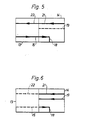
- Fig. 1 shows a preferred embodiment of the present device, and Figs. 2-6 illustrate the function of a particularly preferred embodiment of the valving means of the device according to Fig. 1.
- As is shown in Fig. 1 the device according to the present invention comprises preferably a dialyzer 1, an enzyme reactor 2, a measuring unit 3, a temperature sensor 4, a deaerator 5, and a
flow changing device 6. These elements are known to the skilled person and will therefore not necessarily be described in more detail herein. For further information reference is instead made to any of the above-mentioned patents. - As is shown in Fig. 1, said elements are preferably arranged on the top side of a stack of plates 7, 8, 9 and in communication with each other through a channel system. Example of the preferred channel system may be the channel system as described in our EP-A-0 102 458 published on 14.3.84. Briefly, this channel system is composed of channels being formed between the stacked plates and a part of which is shown in Fig. 1 in the form of
tubes 10, 11, 12 which are arranged over a pump hole P through the plates to thereby provide a means for pumping the individual liquids in the channel system. - From Fig. 1 it can be seen that the present device also includes a valving means (designated 1 in Fig. 1) which will be described in more detail in the following with reference to Figs. 2-6.
- The valving means comprises preferably a
valve piece 13, which is movable between two positions, and a stationary offixed part 14, whereby themovable valve part 13 with its oneend 13a conveniently is releasably attached to a corresponding end 14a of thefixed valve part 14. - The
movable valve part 13 comprises an openable andclosable inlet channel 15 for the complex medium, for example blood, which is adapted to be withdrawn from a patient by means of acannula 16 andtube 17. Theinlet channel 15 is in turn connectable to the dialyzer 1 via acorresponding outlet channel 18 in thefixed valve part 14 and the not shown channel system between theplates 10, 11, 12. - The
fixed valve part 14 comprises aninlet channel 19 for calibration solution, whereby theinlet channel 19 is directly connectable to theoutlet channel 18 via agroove 20 formed in theend 13a of themovable valve part 13, as will be described in the following. - Furthermore, the
fixed valve part 14 preferably comprises aninlet channel 21 for anticoagulant, whereby this channel is directly connectable to theoutlet channel 18 via saidgroove 20 of themovable valve part 13, and indirectly connectable to theoutlet channel 18 via acorresponding channel 22 of themovable valve part 13 and atube 23 which via acannula 16 is in communication with thetube 17 forthe complex medium and consequently, theinlet channel 15 in themovable valve part 13, as mentioned above. - The respective source for calibration solution and anticoagulant may for example be the container which is described in the Swedish Patent Application No. 8104146-7 Published on 4.1.83, and which can be in communication with the channel system in the plates 7, 8, 9 in the manner as described in our EP-A-0 102 458. Preferably, this container is provided with a level marking of the kind as described in the Swedish Patent Application No. 8104147-7, published 4.1.83.
- In Fig. 1 you may furthermore see an
inlet 25 for the calibration solution connected to thechannel 19 for said solution, aninlet 26 for the anticoagulant connected to theinlet channel 21 for said anticoagulant, aninlet 27 for the dialysis liquid which is being pumped to the dialyzer by means of thepumping segment 10 and anoutlet 28 for the consumed dialysis liquid, calibration solution and complex medium. - When calibration is to be performed with the device according to the invention the valving means is set, preferably by means of an arm 24, in the position as shown in Figs. 2 and 3. In order to facilitate the comparison between the Figs. 2, 3 and 4 they have been provided with the letters a-I at fixed positions corresponding to the hour figures of a watch. As is shown in these figures the
inlet channel 19 for calibration solution in thefixed valve part 14 is in communication with thegroove 20 at 20a and via this groove at 20b in communication with theoutlet channel 18 in thefixed valve part 14 which, as described, is in communication with the dialyzer 1 via the channel system between the plates 7, 8, 9. Theinlet channel 21 for anticoagulant in thefixed valve part 14 is in communication with thegroove 20 at 20c and via this groove at 20b in communication with theoutlet channel 18. Furthermore, it can be seen from Figs. 2 and 3 that the communication between theinlet channel 15 for the complex medium in themovable valve part 13 and theoutlet channel 18 is interrupted. The communication between theinlet channel 21 for anticoagulant in thefixed valve part 14 and thecorresponding channel 22 in themovable valve part 13 is also interrupted. - During calibration calibration solution will thus be pumped from a not shown source in communication with an
inlet 25 and through the channel system between the plates 7, 8, 9 into theinlet channel 19 in thefixed valve part 14 and via thegroove movable valve part 13 into theoutlet channel 18 in thefixed valve part 14 and from this via the channel system between the plates 7, 8, 9 to the dialyzer 1. From the dialyzer the calibration solution is then pumped via the channel system to a not shown waste container in communication with anoutlet 28 in the manner as described in our PE-A-0 102 458. Simultaneously anticoagulant is pumped from a not shown source in communication with aninlet 26 through the tube 12 into theinlet channel 21 in thefixed valve part 14 and from this channel to theoutlet 18 via thegroove outlet channel 18 through the same channel system as the calibration solution. Thereby mixing of anticoagulant and calibration solution is obtained when these two flows meet in thegroove - During concentration measurement of the low molecular weight compound (for example glucose) in the complex medium (for example blood) the valving means is set in the position as shown in Figs. 2 and 3, and 4, respectively. In this position the
inlet channel 15 for the blood in themovable valve part 13 is in direct communication with theoutlet channel 18 in thefixed valve part 14 and, as described above, in communication with the dialyzer 1 via the not shown channel system between the plates 7, 8, 9. Furthermore, in this position theinlet channel 21 for anticoagulant in thefixed valve part 14 is in communication with theoutlet channel 18 via thecorresponding channel 22 in themovable valve part 13, thetube 23, thecannula 16, thetube 17 and theinlet channel 15 in themovable valve part 13 for the blood. In this position the direct communication between theinlet channel 21 in thefixed valve part 14 and theoutlet channel 18 is interrupted as well as theinlet channel 19 for calibration solution in thefixed valve part 14 and theoutlet channel 18. - During concentration measurement of the low molecular weight compound the blood is thus withdrawn from for example a patient through the
cannula 16 and pumped to the dialyzer 1 via thetube 17,inlet channel 15 in themovable valve part 13, theoutlet channel 18 in thefixed valve part 14 and the not shown channel system between the plates 7, 8, 9. Simultaneously, anticoagulant is pumped into theinlet channel 21 in thefixed valve part 14 in the manner as described above and to thecannula 16 via thecorresponding channel 22 in themovable valve part 13 and thetube 23. From thecannula 16 the anticoagulant will then follow the same flow pathway as the blood. Mixing of anticoagulant and blood within thecannula 16 is thereby provided where these two flows meet. - From the above description it is apparent that by means of the present device it is possible at intervals during the measurement of the low molecular weight compound in the complex medium to -calibrate the measuring unit 3 by simply setting the valving means in its two respective positions for calibration and measuring.
- The risk of coagulation in the
cannula 16 andtube 17 during the calibration, i.e. when these two elements are filled with for example blood which then is quiescent, is avoided by the fact that the blood simultaneously and continuously is mixed with anticoagulant which thus meets the blood flow within thecannula 16. - A further essential advantage which is achieved according to the invention is that the
tube 23 not necessarily must be disconnected from thecannular 16 during the calibration, which is particularly accentuated in cases where particularly long cannulas are used. According to the invention it is thus possible to maintain thetube 23 for anticoagulant in communication with thecannula 16 during the whole measuring procedure. - The device according to the present invention is adapted for use in connection with concentration measurements of low molecular weight compounds in a complex medium. Specifically, it is adapted for measuring of concentration of glucose in blood of a patient, but it can also be used in quantitative and/or qualitative determination of low molecular weight compounds in other complex media than blood, for example microbiological culturing chambers.
Claims (12)
Priority Applications (1)
| Application Number | Priority Date | Filing Date | Title |
|---|---|---|---|
| AT83105530T ATE24400T1 (en) | 1982-06-15 | 1983-06-06 | CONCENTRATION MEASUREMENT DEVICE. |
Applications Claiming Priority (2)
| Application Number | Priority Date | Filing Date | Title |
|---|---|---|---|
| SE8203696 | 1982-06-15 | ||
| SE8203696A SE453754B (en) | 1982-06-15 | 1982-06-15 | DEVICE FOR SEATING THE CONCENTRATION OF A LAYER MOLECULAR SUBSTANCE IN A COMPLEX MEDIUM |
Publications (2)
| Publication Number | Publication Date |
|---|---|
| EP0102457A1 EP0102457A1 (en) | 1984-03-14 |
| EP0102457B1 true EP0102457B1 (en) | 1986-12-30 |
Family
ID=20347065
Family Applications (1)
| Application Number | Title | Priority Date | Filing Date |
|---|---|---|---|
| EP19830105530 Expired EP0102457B1 (en) | 1982-06-15 | 1983-06-06 | Device for measuring of concentration |
Country Status (6)
| Country | Link |
|---|---|
| US (1) | US4587219A (en) |
| EP (1) | EP0102457B1 (en) |
| JP (1) | JPS596065A (en) |
| AT (1) | ATE24400T1 (en) |
| DE (1) | DE3368520D1 (en) |
| SE (1) | SE453754B (en) |
Families Citing this family (8)
| Publication number | Priority date | Publication date | Assignee | Title |
|---|---|---|---|---|
| US4702889A (en) * | 1986-01-16 | 1987-10-27 | Coulter Electronics Inc. | Liquid sampling valve |
| US4822569A (en) * | 1986-06-09 | 1989-04-18 | Fisher Scientific Company | Rotary shear valve with cleaning feature and method of using same |
| SE451894B (en) * | 1986-08-15 | 1987-11-02 | Gambro Ab | ANALYTICAL SYSTEM CONTAINING MEASURES FOR BLOOD SAMPLING, AND FOR CONDUCTING PREVENT A METAL ELECTRODE, AND FOR SUPPLY OF DILUTING OR ANTICOAGULATING FLUID |
| SE9000192L (en) * | 1990-01-19 | 1991-07-20 | Gambro Ab | SYSTEM RESPECTIVE SATISFACTION MEASURING THE CONTENT OF A SUBSTANCE IN A SOLUTION OR DISPERSION OF THE SAME, WHEREAS THE SUBSTANCE IS CONSIDERED BY A SUBSTANCE THAT IS NOT ELECTRICALLY CONDUCTIVE OR WELL ELECTRICALLY CONDUCTIVE |
| DE4424494A1 (en) * | 1994-07-12 | 1996-01-25 | Danfoss As | Method for calibrating an analysis system and analysis system |
| US6562906B2 (en) * | 2000-08-11 | 2003-05-13 | E. I. Du Pont De Nemours And Company | Bi-modal ionomers |
| EP2154521B1 (en) * | 2007-04-17 | 2012-08-22 | ARKRAY, Inc. | Method and apparatus for measuring substrate concentration |
| US20230152189A1 (en) * | 2021-11-17 | 2023-05-18 | Analog Devices International Unlimited Company | Sensing system with improved fluidics control |
Family Cites Families (13)
| Publication number | Priority date | Publication date | Assignee | Title |
|---|---|---|---|---|
| US3542071A (en) * | 1968-05-10 | 1970-11-24 | Hewlett Packard Co | Fluid flow control valve |
| JPS4820995B1 (en) * | 1968-07-08 | 1973-06-25 | ||
| US3626938A (en) * | 1970-06-30 | 1971-12-14 | Antonio A Versaci | Hemodialysis shunt valve device with body connecting means |
| US3885439A (en) * | 1973-10-24 | 1975-05-27 | Hoffmann La Roche | Rotating sampling valve |
| SE396819B (en) * | 1975-12-31 | 1977-10-03 | Gambro Ab | METHOD AND DEVICE FOR DETERMINING THE CONCENTRATION OF A LOW MOLECULAR ASSOCIATION IN A COMPLEX MEDIUM BY DIALYSIS |
| US4119406A (en) * | 1976-05-06 | 1978-10-10 | Miles Laboratories, Inc. | Calibration apparatus |
| DE2642232C3 (en) * | 1976-09-20 | 1980-05-14 | Boehringer Mannheim Gmbh, 6800 Mannheim | Method and device for the continuous determination of the concentration of an enzyme substrate |
| SE402980B (en) * | 1976-11-30 | 1978-07-24 | Gambro Ab | METHOD AND DEVICE FOR DELETING A CONCENTRATED SOLUTION, PREFERABLY IN CONNECTION WITH ANALYSIS, WHICH THE SOLUTION TOGETHER WITH THE DELIVERY IS SUCKED TO A PUMP DEVICE |
| SE7613375L (en) * | 1976-11-30 | 1978-05-31 | Gambro Ab | METHOD AND DEVICE FOR SATURATION OF THE CONCENTRATION OF A LOW MOLECULAR ASSOCIATION IN A COMPLEX MEDIUM |
| JPS53111782A (en) * | 1977-03-03 | 1978-09-29 | Jeol Ltd | Sampling and metering system |
| SE442640B (en) * | 1977-12-16 | 1986-01-20 | Gambro Lundia Ab | SET AND DEVICE TO META THE CONCENTRATION OF A SUBSTANCE IN A LIQUID MEDIUM |
| US4152391A (en) * | 1977-12-16 | 1979-05-01 | Coulter Electronics, Inc. | Liquid transfer valve |
| US4298026A (en) * | 1979-12-17 | 1981-11-03 | Instrumentation Laboratory Inc. | Spool valve |
-
1982
- 1982-06-15 SE SE8203696A patent/SE453754B/en not_active IP Right Cessation
-
1983
- 1983-06-06 DE DE8383105530T patent/DE3368520D1/en not_active Expired
- 1983-06-06 EP EP19830105530 patent/EP0102457B1/en not_active Expired
- 1983-06-06 AT AT83105530T patent/ATE24400T1/en not_active IP Right Cessation
- 1983-06-07 US US06/501,807 patent/US4587219A/en not_active Expired - Fee Related
- 1983-06-15 JP JP58107587A patent/JPS596065A/en active Pending
Also Published As
| Publication number | Publication date |
|---|---|
| EP0102457A1 (en) | 1984-03-14 |
| SE8203696L (en) | 1983-12-16 |
| US4587219A (en) | 1986-05-06 |
| SE453754B (en) | 1988-02-29 |
| DE3368520D1 (en) | 1987-02-05 |
| JPS596065A (en) | 1984-01-13 |
| ATE24400T1 (en) | 1987-01-15 |
Similar Documents
| Publication | Publication Date | Title |
|---|---|---|
| US5046496A (en) | Sensor assembly for measuring analytes in fluids | |
| EP0503047B1 (en) | Apparatus for preparation of solutions from concentrates | |
| US4898675A (en) | System and method for continuously fractionating blood in situ | |
| US4759371A (en) | Implantable, calibrateable measuring instrument for a body substance and a calibrating method | |
| US4895657A (en) | Apparatus for hemodialysis | |
| EP0657030B1 (en) | Calibration solutions useful for analyses of biological fluids and methods employing same | |
| EP0179129B1 (en) | Self-calibrating single-use sensing device for clinical chemistry analyzer | |
| US4818361A (en) | Combined pH and dissolved carbon dioxide gas sensor | |
| US4263808A (en) | Noninvasive pressure monitor | |
| US5725773A (en) | Method and apparatus for determining the quantity of oremic toxins removed by a hemodialysis treatment | |
| US4468329A (en) | Hemofiltration system and safety system therefor | |
| US4436620A (en) | Integral hydraulic circuit for hemodialysis apparatus | |
| JP2939340B2 (en) | Methods for delivering and collecting fluids | |
| EP0102457A1 (en) | Device for measuring of concentration | |
| GB1601855A (en) | Dialysis apparatus | |
| US12048791B2 (en) | Peritoneal dialysis fluid preparation and/or treatment devices methods and systems | |
| EP1065495B1 (en) | Blood component separation apparatus and method | |
| US4293307A (en) | Method and apparatus for analyzing liquid | |
| EP3254712B1 (en) | Treatment solution preparation device and blood processing system | |
| US20110036768A1 (en) | Continuous blood purification system provided with syringe pumps | |
| EP0102458A1 (en) | Device for measuring of concentration of a low molecular weight compound in a complex medium | |
| EP1950568B1 (en) | Biological component measuring unit | |
| EP0069247B1 (en) | An apparatus for measuring the concentration of a low-molecular compound in a complex medium, especially whole blood | |
| CA1125663A (en) | Method and apparatus for determining ultrafiltration during dialysis | |
| EP3647781B1 (en) | Measuring cartridge for measuring a liquid sample |
Legal Events
| Date | Code | Title | Description |
|---|---|---|---|
| PUAI | Public reference made under article 153(3) epc to a published international application that has entered the european phase |
Free format text: ORIGINAL CODE: 0009012 |
|
| AK | Designated contracting states |
Designated state(s): AT BE CH DE FR GB IT LI LU NL |
|
| 17P | Request for examination filed |
Effective date: 19840525 |
|
| ITF | It: translation for a ep patent filed | ||
| GRAA | (expected) grant |
Free format text: ORIGINAL CODE: 0009210 |
|
| AK | Designated contracting states |
Kind code of ref document: B1 Designated state(s): AT BE CH DE FR GB IT LI LU NL |
|
| PG25 | Lapsed in a contracting state [announced via postgrant information from national office to epo] |
Ref country code: AT Effective date: 19861230 |
|
| REF | Corresponds to: |
Ref document number: 24400 Country of ref document: AT Date of ref document: 19870115 Kind code of ref document: T |
|
| REF | Corresponds to: |
Ref document number: 3368520 Country of ref document: DE Date of ref document: 19870205 |
|
| ET | Fr: translation filed | ||
| PG25 | Lapsed in a contracting state [announced via postgrant information from national office to epo] |
Ref country code: LU Free format text: LAPSE BECAUSE OF NON-PAYMENT OF DUE FEES Effective date: 19870630 |
|
| PGFP | Annual fee paid to national office [announced via postgrant information from national office to epo] |
Ref country code: NL Payment date: 19870630 Year of fee payment: 5 |
|
| PLBE | No opposition filed within time limit |
Free format text: ORIGINAL CODE: 0009261 |
|
| STAA | Information on the status of an ep patent application or granted ep patent |
Free format text: STATUS: NO OPPOSITION FILED WITHIN TIME LIMIT |
|
| 26N | No opposition filed | ||
| PG25 | Lapsed in a contracting state [announced via postgrant information from national office to epo] |
Ref country code: LI Effective date: 19880630 Ref country code: CH Effective date: 19880630 |
|
| PG25 | Lapsed in a contracting state [announced via postgrant information from national office to epo] |
Ref country code: NL Effective date: 19890101 |
|
| NLV4 | Nl: lapsed or anulled due to non-payment of the annual fee | ||
| REG | Reference to a national code |
Ref country code: CH Ref legal event code: PL |
|
| PGFP | Annual fee paid to national office [announced via postgrant information from national office to epo] |
Ref country code: BE Payment date: 19900704 Year of fee payment: 8 |
|
| PGFP | Annual fee paid to national office [announced via postgrant information from national office to epo] |
Ref country code: DE Payment date: 19900726 Year of fee payment: 8 |
|
| ITTA | It: last paid annual fee | ||
| PG25 | Lapsed in a contracting state [announced via postgrant information from national office to epo] |
Ref country code: BE Effective date: 19910630 |
|
| BERE | Be: lapsed |
Owner name: GAMBRO LUNDIA A.B. Effective date: 19910630 |
|
| PG25 | Lapsed in a contracting state [announced via postgrant information from national office to epo] |
Ref country code: DE Effective date: 19920401 |
|
| PGFP | Annual fee paid to national office [announced via postgrant information from national office to epo] |
Ref country code: FR Payment date: 19920522 Year of fee payment: 10 |
|
| PGFP | Annual fee paid to national office [announced via postgrant information from national office to epo] |
Ref country code: GB Payment date: 19920605 Year of fee payment: 10 |
|
| PG25 | Lapsed in a contracting state [announced via postgrant information from national office to epo] |
Ref country code: GB Effective date: 19930606 |
|
| GBPC | Gb: european patent ceased through non-payment of renewal fee |
Effective date: 19930606 |
|
| PG25 | Lapsed in a contracting state [announced via postgrant information from national office to epo] |
Ref country code: FR Effective date: 19940228 |
|
| REG | Reference to a national code |
Ref country code: FR Ref legal event code: ST |