EP0102336B1 - Ausstellungs- und Lagergestell - Google Patents
Ausstellungs- und Lagergestell Download PDFInfo
- Publication number
- EP0102336B1 EP0102336B1 EP83850222A EP83850222A EP0102336B1 EP 0102336 B1 EP0102336 B1 EP 0102336B1 EP 83850222 A EP83850222 A EP 83850222A EP 83850222 A EP83850222 A EP 83850222A EP 0102336 B1 EP0102336 B1 EP 0102336B1
- Authority
- EP
- European Patent Office
- Prior art keywords
- members
- article
- frame
- display
- storage rack
- Prior art date
- Legal status (The legal status is an assumption and is not a legal conclusion. Google has not performed a legal analysis and makes no representation as to the accuracy of the status listed.)
- Expired
Links
- 230000007935 neutral effect Effects 0.000 claims 1
- 230000007812 deficiency Effects 0.000 description 1
- 238000004519 manufacturing process Methods 0.000 description 1
- 229920003023 plastic Polymers 0.000 description 1
- 239000004033 plastic Substances 0.000 description 1
- 239000007787 solid Substances 0.000 description 1
Images

Classifications
-
- A—HUMAN NECESSITIES
- A47—FURNITURE; DOMESTIC ARTICLES OR APPLIANCES; COFFEE MILLS; SPICE MILLS; SUCTION CLEANERS IN GENERAL
- A47F—SPECIAL FURNITURE, FITTINGS, OR ACCESSORIES FOR SHOPS, STOREHOUSES, BARS, RESTAURANTS OR THE LIKE; PAYING COUNTERS
- A47F7/00—Show stands, hangers, or shelves, adapted for particular articles or materials
- A47F7/02—Show stands, hangers, or shelves, adapted for particular articles or materials for jewellery, dentures, watches, eye-glasses, lenses, or the like
- A47F7/024—Show stands, hangers, or shelves, adapted for particular articles or materials for jewellery, dentures, watches, eye-glasses, lenses, or the like with provisions for preventing unauthorised removal
- A47F7/0246—Show stands, hangers, or shelves, adapted for particular articles or materials for jewellery, dentures, watches, eye-glasses, lenses, or the like with provisions for preventing unauthorised removal for rectangular articles, e.g. books, cassettes
Definitions
- the present invention relates to a display and storage rack with swingable frames, particularly for articles that are easily stealable and therefore difficult to display, each frame including at least one shelf space having a depth and a free height closely compatible with the depth and height of an article and defined laterally by two side members and vertically by a top member and bottom member, said defining members having projections for preventing removal of the article from the shelf space and extending from the top and bottom members in the area of the top and bottom portions of the article and a distance along the front and rear side of the article, at least one of said projections being movable vertically from a position in which a portion, or the whole, of its length engages against the front or rear side of the article and prevents its removal from the shelf space to a position in which substantially the whole of its length is away from the vertical extent of the article.
- GB-A-1 459 996 GB-A-1 459 996
- DE-A-2 701975 and DE-B-2 156 050 Similar structures in the prior art appearfor example in GB-A-1 459 996, DE-A-2 701975 and DE-B-2 156 050.
- the display unit disclosed in GB-A-1 459 996 consists of a first frame member having a plurality of spaced transversely extending shelf-like members with solid supporting surfaces for articles.
- Projections or flat strips for locking the articles in place in the shelf-like members in the first frame member are integrally formed with a second frame member, which is slidably movable relative to said first frame member and connected thereto by a number of pin-and-slot connections allowing relative movement between said first and second members in a vertical direction.
- a problem with this solution is that after removal of the strips from the upper portions of all the articles situated in the rack, the articles fall very easy out from their shelf-like members when moving the display unit or rack and it is a very timewasting work for shop assistants to pick up the articles from the floor and again place them in their right place in the rack.
- the rack according to DE-A-2 701 975 is provided with clamp locking means for preventing removal of articles, said means partly cover the front side of the article and make it difficult to remove the articles when the rack is unlocked.
- the rack disclosed in DE-B-2 156 050 includes supporting means arranged in piles and above each other along five axes. When withdrawing articles from the rack the supporting means have to be displaced vertically.
- the object of the present invention is therefore to provide a rack which meets very high demands from the aspects of display function and handling and by which the disadvantages of this known type of racks have been eliminated.
- the invention is characterised in that at least one of the projections for preventing removal of articles from the rack is provided in each bottom member and extends in a direction in the vertical plane of each frame which lies inside the outermost sideparts of each frame and that at least said top and bottom members comprise hollow sections having cavities, the bottom member cavity being able to accommodate said at least one of the projections having its end portions coacting with at least one respective vertically running section extending in a respective cavity inside the respective side member, said member in its opening position or retracted position being sunk inside the cavity in the horizontal hollow section bottom member whereby the article placed in the shelf space is removable therefrom by tipping out the bottom portion of said article.
- the display and storage rack with its frames functions according to the self-selection principle by the customer selecting the desired article and obtaining service only for unlocking and taking out the article from the appropriate shelf space in a frame.
- the rack having the frames disposed in a wall mounting or the like with the frames being able to be swung through an angle of about 135°, the articles in the shelf spaces are displayable on both sides.
- the frames are locked with a locking unit placed in the- lower member of the wall mounting, but can be "leafed through” in the locked position as well.
- the rack is unlocked, enabling all the frames to be opened separately with the aid of a handwheel at the lower outer edge of the frames.
- the design of the frames enables them to be both right- or lefthand hung, which means that the goods can be completely exposed independent of how the rack is placed.
- the frames are furthermore provided with a spring means, the function of which is to return the frames to their initial position after the customer has leafed through them.
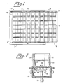
- Figure 1 illustrates an embodiment of the rack intended for mounting on a wall or the like, with the frames fitted into the wall mounting swung to the right in their initial displaying position
- Figure 2 is a sectional view through the wall mounting with a swingably adapted frame fitted to it
- Figure 3 is a cross section through a shelf space in the frame illustrated in Figures 1 and 2
- Figure 4 is a cross section of a bottom member in a frame, and from the figure will be seen the movement of a locking profile in the frame
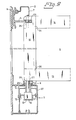
- Figure 5 is a cross section through a side member of a shelf space in the frame
- Figure 6 is a plan view of a spring means for returning the frames to their initial position
- Figure 7 is a side view of a locking actuating means for the bottom member of the wall mounting.
- the wall mounting 1 comprises a top member 2 and a bottom member 3 connected by a vertical intermediate member 4.
- the top member 2 of the wall mounting 1 carries brackets 5, in which the respective frame 6 is suspendable, the top member 2 includes parts 7 and 8.
- Part 7 is hinged to part 8 which is intended to be fixed to a wall or the like, such that part 7 can be pivoted upwards to allow positioning of a frame 6, after which parts 7 and 8 are screwed together.
- the frames 6 cannot be removed by unauthorized persons.
- the holes 9 are associated with a two-way return spring means 37, illustrated in Figure 6.
- the bottom member 3 of the wall mounting 1 includes a locking unit, which locks all the frames 6 and functions as follows.
- a member 10 Inside the bottom member 3 of the wall mounting 1 there is a member 10 with a U-shaped cross section, the upper tips of which have outwardly projecting flanges respectively coacting with two grooves 11,12 formed in member 3.
- the member 10 is displaced with the aid of a locking cylinder and key not shown on the drawing, and is provided with lock-actuating means 13, one for each frame 6.
- the means 13 are provided with a sloping surface, as is apparent from Figure 7. In a locked condition the member 10 cannot be displaced, and when in the unlocked condition it is displaceable for moving the means 13 into, or out of, their displaceable locking position.
- the frames 6 comprise two horizontal members 14, 15 and two vertical side members 16, 17 having hollow sections. These hollow sections 14-17 are joined at the corners with special corner fittings 24.
- a plurality of shelves 18 is arranged between the two vertical side members 16, 17. As will be seen from Figure 3, the shelves 18 keep articles A in place by an inverted U-section at the upper edge including projections or flanges 19,20 and two L-sections 21, 22 forming a U at the bottom edge.
- the L section 21 is rigidly mounted to the vertical side members 16, 17 while the other L-section 22 is connected at either end to two vertically running U-sections 23 ( Figure 5), glidably arranged in a special cavity 30 in the vertical side frame members 16,17. Articles A are thus kept in place by means of the flanges 19, 20, 21, 22.
- the interconnected L-sections 22 and the U-sections 23 are 'raised and lowered by a lever mechanism 32 (see Figure 4) in a cavity of the member 15 in the frames 6, said mechanism mainly consisting of a locking profile 33 which is pivotable between two positions and extends internally in member 15.
- One edge 34 of the profile 33 is pivotably attached to the upper portion of the cavity via a hinge structure 35 such that the other free edge 36 is disposed for actuating the vertical movement of the U-sections 23 in the member 16, and thereby the movement of the L-sections 22.
- the corner fittings 24 of the frames 6 are fixable in the wall mounting 1 at the upper part of the frame 6 with the aid of a recess 25 in the outer part of the corner fittings 24, this recess accommodating the end of the bracket 5, to which it is lockable with the aid of a pin 26 through a hole in the bracket 5.
- the fitting 24 is lockable with the aid of a pin 27 at the bottom portion of said fitting 24.
- the pin 27 is mountable in a journal bushing 28 in the hole 9 of the bottom member 3 of the wall mounting 1, said bushing 28 is provided with a slot.
- the pin 27 is actuated vertically by the means 13 on the member 10 which, as previously mentioned, is displaceable.
- the journalling bushings 28, in the bottom member 3 of the wall mounting 1 are taken through a plastics collar 29 and fits snugly therein.
- the portion of the bushing 28 projecting below the collar 29 and the upper portion of the bottom member 3 is furthermore adapted for coacting with the two-way functioning return spring means 37.
- This spring means 37 is designed such that it provides return bias when e.g. the bushing is turned clockwise in Figure 6 and after release returns to its initial position. During leafing or swinging of the frames 6, when the bushing is turned anticlockwise the spring means 37 is again biased and returns to the initial position after turning pressure has ceased.
- the spring means 37 comprises, as will be seen from Figure 6, a frame portion 38 with a rotatably mounted bushing 39 therein.
- each of at least two helical springs 40, 41 are attached to the bushing 39, the other ends of these springs 40, 41 are attached to the frame portion 38 such that the bushing 39, through which the shaft of the bushing 28 and the pin 27 extend non-rotatably, is rotatable about 135° in both directions from its initial position.
Landscapes
- Display Racks (AREA)
- Fittings On The Vehicle Exterior For Carrying Loads, And Devices For Holding Or Mounting Articles (AREA)
- Assembled Shelves (AREA)
Claims (6)
dadurch gekennzeichnet, daß der eine Vorsprung (22) an jedem Bodenteil (15; 18) vorgesehen ist und sich in einer Richtung in der vertikalen Ebene jedes Rahmens (6) erstreckt, die innerhalb der äußersten Seitenteile jedes Rahmens (6) liegt, und daß wenigstens die Ober- und Bodenteile (18) hohle Abschnitte mit Hohlräumen (31) umfassen, von denen der Hohlraum der Bodenteile den einen Vorsprung (22) aufnehmen kann, mit dessen Endbereichen wenigstens ein entsprechend vertikal verlaufender Abschnitt (23) zusammenwirkt, der sich in einen entsprechenden Hohlraum (30) innerhalb des entsprechenden Seitenteils (16; 17) erstreckt, so daß der Vorsprung (22) in seiner öffnenden Position oder zurückgezogenen Position innerhalb des Hohlraumes (31) im horizontalen hohlen Abschnitt des Bodenteils (15; 18) versenkt ist, wodurch der in dem Regalfach angeordnete Artikel (A) durch ein Antippen seines unteren Bereichs aus dem Regalfach entnehmbar ist.
Priority Applications (1)
| Application Number | Priority Date | Filing Date | Title |
|---|---|---|---|
| AT83850222T ATE32170T1 (de) | 1982-08-27 | 1983-08-23 | Ausstellungs- und lagergestell. |
Applications Claiming Priority (2)
| Application Number | Priority Date | Filing Date | Title |
|---|---|---|---|
| SE8204913A SE432046B (sv) | 1982-08-27 | 1982-08-27 | Anordning vid skylt- och forvaringsstell |
| SE8204913 | 1982-08-27 |
Publications (2)
| Publication Number | Publication Date |
|---|---|
| EP0102336A1 EP0102336A1 (de) | 1984-03-07 |
| EP0102336B1 true EP0102336B1 (de) | 1988-01-27 |
Family
ID=20347644
Family Applications (1)
| Application Number | Title | Priority Date | Filing Date |
|---|---|---|---|
| EP83850222A Expired EP0102336B1 (de) | 1982-08-27 | 1983-08-23 | Ausstellungs- und Lagergestell |
Country Status (6)
| Country | Link |
|---|---|
| US (1) | US4566598A (de) |
| EP (1) | EP0102336B1 (de) |
| JP (1) | JPS5962017A (de) |
| AT (1) | ATE32170T1 (de) |
| DE (1) | DE3375450D1 (de) |
| SE (1) | SE432046B (de) |
Families Citing this family (11)
| Publication number | Priority date | Publication date | Assignee | Title |
|---|---|---|---|---|
| JP3158272B2 (ja) * | 1996-08-09 | 2001-04-23 | 株式会社サンエイ | ソフト収納ケースの保持具 |
| US6202454B1 (en) * | 1997-05-16 | 2001-03-20 | Tomato Land Display Systems, Inc. | Anti-theft security case |
| US7467772B2 (en) * | 2004-10-12 | 2008-12-23 | Target Brands, Inc. | Pivoting display stand |
| US7559437B2 (en) * | 2007-12-07 | 2009-07-14 | Displays Plus, Inc. | Merchandise dispenser with coil actuation |
| US10143301B2 (en) * | 2011-01-21 | 2018-12-04 | Anita Brochette Summerville | Cabinet conversion panels |
| US10885753B2 (en) | 2018-03-21 | 2021-01-05 | Fasteners For Retail, Inc. | Anti-theft device with remote alarm feature |
| US10993550B2 (en) | 2018-03-21 | 2021-05-04 | Fasteners For Retail, Inc. | Anti-theft retail merchandise pusher with remote alarm feature |
| AU2020252550A1 (en) | 2019-04-05 | 2021-10-14 | Fasteners For Retail, Inc. | Anti-theft pusher with incremental distance detection |
| US11154143B2 (en) | 2019-09-30 | 2021-10-26 | Fasteners For Retail, Inc. | Anti-theft hook with integrated loss prevention functionality |
| US12437262B2 (en) | 2021-08-23 | 2025-10-07 | Fasteners For Retail, Inc. | Anti-sweeping hook with integrated inventory monitoring and/or loss prevention functionality |
| US12433428B2 (en) | 2021-08-23 | 2025-10-07 | Fasteners For Retail, Inc. | Anti-sweeping hook with integrated inventory monitoring and/or loss prevention functionality |
Family Cites Families (6)
| Publication number | Priority date | Publication date | Assignee | Title |
|---|---|---|---|---|
| GB1373082A (en) * | 1970-11-11 | 1974-11-06 | Gedye R B | Display units |
| US3805962A (en) * | 1972-06-19 | 1974-04-23 | A Bendiksen | Arrangement in combined display and sales racks |
| GB1459996A (en) * | 1972-10-13 | 1976-12-31 | Rumble C S J | Display units more particularly for cassettes tape cartridges books and the like |
| US3915306A (en) * | 1972-11-29 | 1975-10-28 | Penney Co J C | Display case |
| DE2335965A1 (de) * | 1973-07-14 | 1975-01-30 | Orschler Produktion Kg | Diebstahlsicherer kassetteneinsatz |
| SE395602B (sv) * | 1976-01-23 | 1977-08-22 | Fors & Forss | Anordning vid staell foer varor |
-
1982
- 1982-08-27 SE SE8204913A patent/SE432046B/sv not_active IP Right Cessation
-
1983
- 1983-08-23 EP EP83850222A patent/EP0102336B1/de not_active Expired
- 1983-08-23 AT AT83850222T patent/ATE32170T1/de not_active IP Right Cessation
- 1983-08-23 DE DE8383850222T patent/DE3375450D1/de not_active Expired
- 1983-08-26 US US06/526,650 patent/US4566598A/en not_active Expired - Fee Related
- 1983-08-26 JP JP58155142A patent/JPS5962017A/ja active Pending
Also Published As
| Publication number | Publication date |
|---|---|
| EP0102336A1 (de) | 1984-03-07 |
| SE432046B (sv) | 1984-03-19 |
| ATE32170T1 (de) | 1988-02-15 |
| JPS5962017A (ja) | 1984-04-09 |
| SE8204913D0 (sv) | 1982-08-27 |
| SE8204913L (sv) | 1984-02-28 |
| US4566598A (en) | 1986-01-28 |
| DE3375450D1 (en) | 1988-03-03 |
Similar Documents
| Publication | Publication Date | Title |
|---|---|---|
| US4566598A (en) | Arrangement in display and storage racks | |
| CA1038920A (en) | Locking system for cabinets | |
| US5036779A (en) | Automatic teller machine enclosure | |
| US4915460A (en) | Security system for dispensing racks | |
| US5314244A (en) | Pharmaceutical cabinet locking arrangement | |
| US4468940A (en) | Lock box | |
| CA2034107A1 (en) | Locking anti-tip device | |
| US5871263A (en) | Merchandise display case with an improved gang lock unit | |
| US20150159426A1 (en) | Concealment cavity in a door | |
| US7784886B2 (en) | Filing cabinet with a locking system | |
| US20020070640A1 (en) | Locking mechanism, and locking barrier and cabinet using same | |
| DE2701975A1 (de) | Vorrichtung an gestellen fuer verkaufsverpackungen u.dgl. | |
| US4561704A (en) | ATM Enclosure | |
| US3223466A (en) | Filing cabinet | |
| US8348357B2 (en) | Drawer assembly locking mechanism | |
| US20080016617A1 (en) | Furniture element forming convertible desk and bed | |
| EP2370764B1 (de) | Kältegerät | |
| US3175872A (en) | Cabinets | |
| US20210177150A1 (en) | Outdoor furniture with lockable compartment | |
| EP0385875A1 (de) | Briefkastenanlage mit Gesamtöffnung | |
| KR200433959Y1 (ko) | 전시용 진열장의 잠금장치 | |
| JPS6348772Y2 (de) | ||
| EP0649968A1 (de) | Verschliessbare Box | |
| DE9013388U1 (de) | Vorrichtung zur Aufbewahrung von Wertgegenständen | |
| GB2259447A (en) | Caster support structure for movable table |
Legal Events
| Date | Code | Title | Description |
|---|---|---|---|
| PUAI | Public reference made under article 153(3) epc to a published international application that has entered the european phase |
Free format text: ORIGINAL CODE: 0009012 |
|
| AK | Designated contracting states |
Designated state(s): AT BE CH DE FR GB IT LI NL |
|
| 17P | Request for examination filed |
Effective date: 19840903 |
|
| GRAA | (expected) grant |
Free format text: ORIGINAL CODE: 0009210 |
|
| AK | Designated contracting states |
Kind code of ref document: B1 Designated state(s): AT BE CH DE FR GB IT LI NL |
|
| PG25 | Lapsed in a contracting state [announced via postgrant information from national office to epo] |
Ref country code: NL Effective date: 19880127 Ref country code: LI Effective date: 19880127 Ref country code: IT Free format text: LAPSE BECAUSE OF FAILURE TO SUBMIT A TRANSLATION OF THE DESCRIPTION OR TO PAY THE FEE WITHIN THE PRESCRIBED TIME-LIMIT;WARNING: LAPSES OF ITALIAN PATENTS WITH EFFECTIVE DATE BEFORE 2007 MAY HAVE OCCURRED AT ANY TIME BEFORE 2007. THE CORRECT EFFECTIVE DATE MAY BE DIFFERENT FROM THE ONE RECORDED. Effective date: 19880127 Ref country code: FR Free format text: THE PATENT HAS BEEN ANNULLED BY A DECISION OF A NATIONAL AUTHORITY Effective date: 19880127 Ref country code: CH Effective date: 19880127 Ref country code: BE Effective date: 19880127 Ref country code: AT Effective date: 19880127 |
|
| REF | Corresponds to: |
Ref document number: 32170 Country of ref document: AT Date of ref document: 19880215 Kind code of ref document: T |
|
| REF | Corresponds to: |
Ref document number: 3375450 Country of ref document: DE Date of ref document: 19880303 |
|
| REG | Reference to a national code |
Ref country code: CH Ref legal event code: PL |
|
| NLV1 | Nl: lapsed or annulled due to failure to fulfill the requirements of art. 29p and 29m of the patents act | ||
| EN | Fr: translation not filed | ||
| PG25 | Lapsed in a contracting state [announced via postgrant information from national office to epo] |
Ref country code: GB Free format text: LAPSE BECAUSE OF NON-PAYMENT OF DUE FEES Effective date: 19880823 |
|
| PLBE | No opposition filed within time limit |
Free format text: ORIGINAL CODE: 0009261 |
|
| STAA | Information on the status of an ep patent application or granted ep patent |
Free format text: STATUS: NO OPPOSITION FILED WITHIN TIME LIMIT |
|
| 26N | No opposition filed | ||
| PG25 | Lapsed in a contracting state [announced via postgrant information from national office to epo] |
Ref country code: DE Effective date: 19890503 |
|
| GBPC | Gb: european patent ceased through non-payment of renewal fee |