EP0102275A2 - Entkupplungssperrvorrichtung für einen elektrischen Verbinder - Google Patents
Entkupplungssperrvorrichtung für einen elektrischen Verbinder Download PDFInfo
- Publication number
- EP0102275A2 EP0102275A2 EP83401559A EP83401559A EP0102275A2 EP 0102275 A2 EP0102275 A2 EP 0102275A2 EP 83401559 A EP83401559 A EP 83401559A EP 83401559 A EP83401559 A EP 83401559A EP 0102275 A2 EP0102275 A2 EP 0102275A2
- Authority
- EP
- European Patent Office
- Prior art keywords
- housing
- coupling nut
- electrical connector
- comprised
- decoupling mechanism
- Prior art date
- Legal status (The legal status is an assumption and is not a legal conclusion. Google has not performed a legal analysis and makes no representation as to the accuracy of the status listed.)
- Withdrawn
Links
Images
Classifications
-
- H—ELECTRICITY
- H01—ELECTRIC ELEMENTS
- H01R—ELECTRICALLY-CONDUCTIVE CONNECTIONS; STRUCTURAL ASSOCIATIONS OF A PLURALITY OF MUTUALLY-INSULATED ELECTRICAL CONNECTING ELEMENTS; COUPLING DEVICES; CURRENT COLLECTORS
- H01R13/00—Details of coupling devices of the kinds covered by groups H01R12/70 or H01R24/00 - H01R33/00
- H01R13/62—Means for facilitating engagement or disengagement of coupling parts or for holding them in engagement
- H01R13/639—Additional means for holding or locking coupling parts together, after engagement, e.g. separate keylock, retainer strap
-
- H—ELECTRICITY
- H01—ELECTRIC ELEMENTS
- H01R—ELECTRICALLY-CONDUCTIVE CONNECTIONS; STRUCTURAL ASSOCIATIONS OF A PLURALITY OF MUTUALLY-INSULATED ELECTRICAL CONNECTING ELEMENTS; COUPLING DEVICES; CURRENT COLLECTORS
- H01R13/00—Details of coupling devices of the kinds covered by groups H01R12/70 or H01R24/00 - H01R33/00
- H01R13/46—Bases; Cases
- H01R13/533—Bases, cases made for use in extreme conditions, e.g. high temperature, radiation, vibration, corrosive environment, pressure
-
- H—ELECTRICITY
- H01—ELECTRIC ELEMENTS
- H01R—ELECTRICALLY-CONDUCTIVE CONNECTIONS; STRUCTURAL ASSOCIATIONS OF A PLURALITY OF MUTUALLY-INSULATED ELECTRICAL CONNECTING ELEMENTS; COUPLING DEVICES; CURRENT COLLECTORS
- H01R13/00—Details of coupling devices of the kinds covered by groups H01R12/70 or H01R24/00 - H01R33/00
- H01R13/62—Means for facilitating engagement or disengagement of coupling parts or for holding them in engagement
- H01R13/622—Screw-ring or screw-casing
Definitions
- This invention relates to an electrical connector and more particularly to a mechanism that inhibits accidental decoupling of a connector assembly.
- An electrical connector assembly is generally comprised of two separate housings such as a plug and receptacle connected together by a coupling member mounted on one of the housings.
- Some cylindrically shaped connectors have a threaded coupling member mounted on one housing which mates with threads on another housing so that when the housings are placed together and the coupling member is rotated the housings are drawn together mating the contacts within the housings.
- Such electrical connectors are easily and quickly coupled and decoupled with the use of reasonable forces. However, vibrational forces have a tendency to uncouple these connectors, so some connectors have an anti-decoupling mechanism to avoid this problem.
- One example of such an anti-decoupling mechanism may be found in U.S. Patent 4,109,990 entitled "Electrical Connector Assembly Having Anti-Decoupling" issued August 29, 1978.
- This invention is an electrical connector assembly that has an ' anti-decoupling mechanism that is characterized by an annular ring, comprised of an elastomeric material, located in an annular groove and pressure tight relationship between the coupling nut and housing to which the coupling nut is mounted.
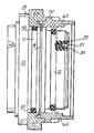
- the single figure illustrates an electrical connector assembly incorporating the principles of the invention.
- the electrical connector includes a shell or housing 10 that has mounted therein a dielectric insert 20 having a plurality of bores 21 therein each containing a respective electrical contact 30.
- a first groove 12 in the connector housing 10 has located therein a rubber 0 ring 60. It is a function of the O ring 60 to provide a moisture seal between the housing 10, the rotatably mounted coupling nut 40, and another housing (not shown).
- the coupling nut 40 is rotatably mounted to the housing 10 by captivating a portion of the coupling nut 40 between the radial flange 13 of the housing 10 and a snap ring 70 located in a groove 14 adjacent the flange 13.
- annular ring 50 Located in the groove 11 is an annular ring 50 comprised of a dielectric material which is in pressure tight contact between the coupling nut 40 and the housing 10.
- the annular ring 50 retards the movement of the coupling nut 40 in either direction and, when the coupling nut is connected to another housing and subjected to vibration, the ring 50 retards rotational movement of the coupling nut 40 thereby preventing unwanted decoupling of the coupling nut 40 from the other housing (not shown).
- the annular member 50 may be comprised of a plastic or elastomeric material and is perferably comprised of elastomeric material having a durometer of about 70.
- To further retard rotational movement of the coupling nut either one or both of the surfaces of the annular ring 50 or the inner surface of the coupling ring 40 may be knurled so as to increase the friction between the two surfaces.
- the connector assembly illustrated shows a coupling nut 40 mounted to the forward portion of the electrical connector but the invention is just as applicable to an electrical connector having the coupling nut 40 mounted behind the radially extending flange 13 of the housing 10. In that instance the groove 14 would be on the rear side of the radially flange 13. Accordingly, it is intented that the illustrative and descriptive material herein be used to limited to the priciples of the invention and not to limit the scope thereof.
Landscapes
- Details Of Connecting Devices For Male And Female Coupling (AREA)
- Connector Housings Or Holding Contact Members (AREA)
Applications Claiming Priority (2)
| Application Number | Priority Date | Filing Date | Title |
|---|---|---|---|
| US402526 | 1982-07-28 | ||
| US06/402,526 US4461526A (en) | 1982-07-28 | 1982-07-28 | Anti-decoupling mechanism for an electrical connector |
Publications (2)
| Publication Number | Publication Date |
|---|---|
| EP0102275A2 true EP0102275A2 (de) | 1984-03-07 |
| EP0102275A3 EP0102275A3 (de) | 1986-05-14 |
Family
ID=23592276
Family Applications (1)
| Application Number | Title | Priority Date | Filing Date |
|---|---|---|---|
| EP83401559A Withdrawn EP0102275A3 (de) | 1982-07-28 | 1983-07-28 | Entkupplungssperrvorrichtung für einen elektrischen Verbinder |
Country Status (4)
| Country | Link |
|---|---|
| US (1) | US4461526A (de) |
| EP (1) | EP0102275A3 (de) |
| JP (1) | JPS5946781A (de) |
| CA (1) | CA1194952A (de) |
Families Citing this family (5)
| Publication number | Priority date | Publication date | Assignee | Title |
|---|---|---|---|---|
| US4990101A (en) * | 1989-12-01 | 1991-02-05 | Itt Corporation | Cover for circular electrical connectors |
| US5786976A (en) * | 1996-07-16 | 1998-07-28 | Hydraflow | Coupling with hard metallic ductile conductive coating |
| US5959828A (en) * | 1996-07-16 | 1999-09-28 | Hydraflow | Coupling with insulated flanges |
| US8668188B2 (en) * | 2010-08-31 | 2014-03-11 | General Electric Company | Slotted spring vibration isolator |
| US9397441B2 (en) | 2013-03-15 | 2016-07-19 | Cinch Connections, Inc. | Connector with anti-decoupling mechanism |
Family Cites Families (10)
| Publication number | Priority date | Publication date | Assignee | Title |
|---|---|---|---|---|
| US3017597A (en) * | 1958-11-13 | 1962-01-16 | Pyle National Co | Electrical connector |
| US3029407A (en) * | 1959-04-15 | 1962-04-10 | Pyle National Co | Electrical connector with pop-in current-continuing means |
| US3727172A (en) * | 1970-10-26 | 1973-04-10 | Deutsch Co Elec Comp | Electrical connector |
| US3971614A (en) * | 1972-11-03 | 1976-07-27 | Akzona Incorporated | Electrical connector with means for maintaining a connected condition |
| US4204740A (en) * | 1974-03-22 | 1980-05-27 | Bunker Ramo Corporation | Connector coupling ring retainer apparatus and electrical connector assembly retaining means |
| US4066314A (en) * | 1976-06-28 | 1978-01-03 | Williams Robert A | Electrical connector backshell accessory indexing body |
| CA1070792A (en) * | 1976-07-26 | 1980-01-29 | Earl A. Cooper | Electrical connector and frequency shielding means therefor and method of making same |
| US4109990A (en) * | 1977-05-26 | 1978-08-29 | The Bendix Corporation | Electrical connector assembly having anti-decoupling mechanism |
| US4268103A (en) * | 1979-02-02 | 1981-05-19 | The Bendix Corporation | Electrical connector assembly having anti-decoupling mechanism |
| US4277125A (en) * | 1979-07-12 | 1981-07-07 | Automation Industries, Inc. | Enhanced detent guide track with dog-leg |
-
1982
- 1982-07-28 US US06/402,526 patent/US4461526A/en not_active Expired - Fee Related
-
1983
- 1983-03-24 CA CA000424397A patent/CA1194952A/en not_active Expired
- 1983-07-27 JP JP58136018A patent/JPS5946781A/ja active Pending
- 1983-07-28 EP EP83401559A patent/EP0102275A3/de not_active Withdrawn
Also Published As
| Publication number | Publication date |
|---|---|
| CA1194952A (en) | 1985-10-08 |
| JPS5946781A (ja) | 1984-03-16 |
| EP0102275A3 (de) | 1986-05-14 |
| US4461526A (en) | 1984-07-24 |
Similar Documents
| Publication | Publication Date | Title |
|---|---|---|
| US4349241A (en) | Electrical connector assembly having enhanced EMI shielding | |
| EP0052539B1 (de) | Kupplungsring für einen elektrischen Verbinder | |
| US4938718A (en) | Cylindrical connector keying means | |
| USRE32787E (en) | Sealing ring for an electrical connector | |
| US4334730A (en) | Insulated from ground bulkhead adapter | |
| US4033654A (en) | Electrical connector | |
| US4239314A (en) | Electrical connector | |
| GB1454099A (en) | Electrical connectors | |
| EP0221952B1 (de) | Kabeldichtung | |
| EP0052530A1 (de) | Kupplungsring eines elektrischen Verbinders mit angeformter Feder | |
| US4154496A (en) | Coupling assembly for resilient electrical connector components | |
| US4359255A (en) | Coupling ring having detent means | |
| US4421373A (en) | Electrical connector having means for sealing against moisture | |
| DE69819888D1 (de) | Unterwassersteckverbinderanordnung | |
| US3792415A (en) | Weatherproof cover for electrical cable connector | |
| US4359256A (en) | Electrical connector coupling member | |
| GB2109645A (en) | Self-locking electrical connector | |
| GB2025158A (en) | Electrical connector having filter contacts mounted in a removable filter module | |
| US4548458A (en) | Electrical connector having a molded anti-decoupling mechanism | |
| EP0052531B1 (de) | Montagemittel eines Einsatzes in das Gehäuse eines elektrischen Verbinders | |
| EP0102275A2 (de) | Entkupplungssperrvorrichtung für einen elektrischen Verbinder | |
| GB2043367A (en) | Electrical connector assembly | |
| US4527851A (en) | Electrical connector assembly having an interfacial seal | |
| US6109945A (en) | Electrical sealed connector | |
| EP0103498A2 (de) | Dichtungsring für einen elektrischen Verbinder |
Legal Events
| Date | Code | Title | Description |
|---|---|---|---|
| PUAI | Public reference made under article 153(3) epc to a published international application that has entered the european phase |
Free format text: ORIGINAL CODE: 0009012 |
|
| AK | Designated contracting states |
Designated state(s): DE FR GB IT |
|
| PUAL | Search report despatched |
Free format text: ORIGINAL CODE: 0009013 |
|
| AK | Designated contracting states |
Kind code of ref document: A3 Designated state(s): DE FR GB IT |
|
| STAA | Information on the status of an ep patent application or granted ep patent |
Free format text: STATUS: THE APPLICATION IS DEEMED TO BE WITHDRAWN |
|
| 18D | Application deemed to be withdrawn |
Effective date: 19860201 |
|
| RIN1 | Information on inventor provided before grant (corrected) |
Inventor name: GALLUSSER, DAVID OTIS Inventor name: MACAVOY, DAVID WARREN Inventor name: FREAR, DAVID LEIGH Inventor name: PUNAKO, STEPHEN |