EP0102261B1 - Method of obtaining a coil with a closed magnetic circuit and a permanent magnet for the ignition of combustion engines - Google Patents
Method of obtaining a coil with a closed magnetic circuit and a permanent magnet for the ignition of combustion engines Download PDFInfo
- Publication number
- EP0102261B1 EP0102261B1 EP19830401361 EP83401361A EP0102261B1 EP 0102261 B1 EP0102261 B1 EP 0102261B1 EP 19830401361 EP19830401361 EP 19830401361 EP 83401361 A EP83401361 A EP 83401361A EP 0102261 B1 EP0102261 B1 EP 0102261B1
- Authority
- EP
- European Patent Office
- Prior art keywords
- permanent magnet
- pack
- magnetic circuit
- clamp
- process according
- Prior art date
- Legal status (The legal status is an assumption and is not a legal conclusion. Google has not performed a legal analysis and makes no representation as to the accuracy of the status listed.)
- Expired
Links
- 238000000034 method Methods 0.000 title claims description 15
- 238000002485 combustion reaction Methods 0.000 title claims description 4
- 239000002184 metal Substances 0.000 claims description 14
- 238000004804 winding Methods 0.000 claims description 14
- 229910001209 Low-carbon steel Inorganic materials 0.000 claims description 3
- 238000005452 bending Methods 0.000 claims description 3
- 230000015572 biosynthetic process Effects 0.000 claims description 3
- 230000000717 retained effect Effects 0.000 claims 1
- 238000009434 installation Methods 0.000 description 4
- 230000002411 adverse Effects 0.000 description 2
- 230000014759 maintenance of location Effects 0.000 description 2
- 210000000621 bronchi Anatomy 0.000 description 1
- 230000004907 flux Effects 0.000 description 1
- 238000010008 shearing Methods 0.000 description 1
Images

Classifications
-
- H—ELECTRICITY
- H01—ELECTRIC ELEMENTS
- H01F—MAGNETS; INDUCTANCES; TRANSFORMERS; SELECTION OF MATERIALS FOR THEIR MAGNETIC PROPERTIES
- H01F38/00—Adaptations of transformers or inductances for specific applications or functions
- H01F38/12—Ignition, e.g. for IC engines
-
- H—ELECTRICITY
- H01—ELECTRIC ELEMENTS
- H01F—MAGNETS; INDUCTANCES; TRANSFORMERS; SELECTION OF MATERIALS FOR THEIR MAGNETIC PROPERTIES
- H01F27/00—Details of transformers or inductances, in general
- H01F27/24—Magnetic cores
- H01F27/245—Magnetic cores made from sheets, e.g. grain-oriented
-
- H—ELECTRICITY
- H01—ELECTRIC ELEMENTS
- H01F—MAGNETS; INDUCTANCES; TRANSFORMERS; SELECTION OF MATERIALS FOR THEIR MAGNETIC PROPERTIES
- H01F27/00—Details of transformers or inductances, in general
- H01F27/24—Magnetic cores
- H01F27/26—Fastening parts of the core together; Fastening or mounting the core on casing or support
- H01F27/266—Fastening or mounting the core on casing or support
-
- H—ELECTRICITY
- H01—ELECTRIC ELEMENTS
- H01F—MAGNETS; INDUCTANCES; TRANSFORMERS; SELECTION OF MATERIALS FOR THEIR MAGNETIC PROPERTIES
- H01F3/00—Cores, Yokes, or armatures
- H01F3/10—Composite arrangements of magnetic circuits
- H01F3/14—Constrictions; Gaps, e.g. air-gaps
-
- H—ELECTRICITY
- H01—ELECTRIC ELEMENTS
- H01F—MAGNETS; INDUCTANCES; TRANSFORMERS; SELECTION OF MATERIALS FOR THEIR MAGNETIC PROPERTIES
- H01F41/00—Apparatus or processes specially adapted for manufacturing or assembling magnets, inductances or transformers; Apparatus or processes specially adapted for manufacturing materials characterised by their magnetic properties
- H01F41/02—Apparatus or processes specially adapted for manufacturing or assembling magnets, inductances or transformers; Apparatus or processes specially adapted for manufacturing materials characterised by their magnetic properties for manufacturing cores, coils, or magnets
- H01F41/0206—Manufacturing of magnetic cores by mechanical means
- H01F41/0233—Manufacturing of magnetic circuits made from sheets
- H01F41/024—Manufacturing of magnetic circuits made from deformed sheets
Definitions
- FIG. 4 is a sectional view, along the line AA, of strips, of sheet metal, constituting the package represented by FIG. 3.
- Figure 13 is a representation, in partial perspective and on a reduced scale, of a second embodiment of the clamping device.
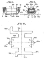
- the clamping device 100, of the package 2a on the permanent magnet 6 consists of a flange 101, FIGS. 8 and 9, which flange 101 is obtained by cutting a sidewall 101 a from a sheet of mild steel, FIG. 10 .:
- the flange 101 has wings 101 b, FIG. 9, which come to bear on the wings 104a of insulating plates 104 interposed between the lateral jibs of the package 2a and of the permanent magnet 6, the holding of which inside the flange 101 is obtained by the prior formation of a hinge 101c which is closed by pressure in the direction of the arrows F, using any known means.
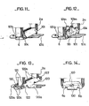
- the flange 101 comprises lugs 101d and 101e, obtained during the cutting of the flange 101a, FIG. 10, which lugs, after successive folding operations are presented parallel to the external face 101f of the flange 101, FIGS. 8 and 9, so that notches 101g and 101h and a side edge 101j formed in the legs 101d and 101e, Figure 10, form openings 101k and 1011 perpendicular to each other, Figures 11, for fixing the ignition coil on the vehicle automobile.
- the flange 101 has protuberances 101m and 101n shown in FIG. 10 in broken lines, the protrusion 101m has a smooth hole 101p in which engages a screw 110, FIG. 12, the protrusion 101 comprising a threaded hole 101 q, FIG. 10, into which the screw 110, FIG. 12 is screwed, so as to reinforce the retention of the package 2a and of the permanent magnet 6 to 1 inside the flange 101.
- the half-flanges 120 are secured to each other using screws 122, one of the half-flanges having smooth holes the other having threaded holes.
Landscapes
- Engineering & Computer Science (AREA)
- Power Engineering (AREA)
- Chemical & Material Sciences (AREA)
- Composite Materials (AREA)
- Manufacturing & Machinery (AREA)
- Ignition Installations For Internal Combustion Engines (AREA)
Description
L'invention concerné un procédé d'obtention d'une bobine à circuit magnétique fermé et à aimant permanent pour l'allumage de moteurs à combustion interne, notamment de véhicules automobiles, bobine comportant un enroulement primaire et un enroulement secondaire logés dans un boîtier isolant qui entoure une des branches du circuit magnétique.The invention relates to a method for obtaining a coil with a closed magnetic circuit and a permanent magnet for the ignition of internal combustion engines, in particular of motor vehicles, coil comprising a primary winding and a secondary winding housed in an insulating housing. which surrounds one of the branches of the magnetic circuit.
Ce circuit est constitué de bandes de tôle, de différentes longueurs, empilées les unes sur les autres et pliées à angle droit de manière à former un circuit magnétique fermé qui est maintenu sur les surfaces actives 51 et 51' de l'aimant permanent.This circuit consists of strips of sheet metal, of different lengths, stacked on each other and bent at right angles so as to form a closed magnetic circuit which is maintained on the active surfaces 51 and 51 'of the permanent magnet.
Un circuit magnétique du type précité est connu, notamment parles documents Suisse CH -A-416817etUS-A-2878855.A magnetic circuit of the aforementioned type is known, in particular from the Swiss documents CH -A-416817 andUS-A-2878855.
Un tel circuit associé à un aimant permanent disposé dans celui-ci comme décrit dans le document EP - A - 072 266 document visé à l'article 54 (3) de la CBE apporte une amélioration importante par rapport à une bobine d'allumage dont le circuit magnétique ne comporte pas d'aimant, en raison du fait de l'utilisation d'une grande partie du cycle d'hystérésis, due à la présence de l'aimant permanent.Such a circuit associated with a permanent magnet placed therein as described in document EP - A - 072 266 document referred to in Article 54 (3) of the EPC brings a significant improvement compared to an ignition coil. the magnetic circuit does not have a magnet, due to the fact of the use of a large part of the hysteresis cycle, due to the presence of the permanent magnet.
Bien que présentant certains avantages technologiques par rapport au circuit décrit dans le FR - 2 484 160, on constate une perte de 20% dans l'utilisation des surfaces actives possibles en contact de l'aimant dans une conception analogue à celle décrite dans le EP - A - 072 266.Although having certain technological advantages compared to the circuit described in FR - 2 484 160, there is a loss of 20% in the use of possible active surfaces in contact with the magnet in a design similar to that described in EP - A - 072 266.
Cette perte de 20%, qui influe défavorablement sur les performances de la bobine d'allumage, est due au fait que la fermeture du circuit magnétique s'effectue par pliage des bandes selon des rayons qui croissent depuis le périmètre intérieur jusqu'au périmètre extérieur. L'invention a pour but de remédier à cet inconvénient et concerne à cet effet un procédé d'obtention d'une bobine d'allumage à circuit magnétique fermé et à aimant permanent, pour l'allumage des moteurs, à combustion interne, bobine comportant des enroulements primaire et secondaire logés dans un boîtier isolant entourant une branche du circuit magnétique, constitué de bandes, de tôle, de largeur E, empilées les unes sur les autres, procédé caractérisé en ce qu'afin d'accroître la surface du circuit magnétique en contact avec les surfaces actives S1, S1' de l'aimant permanent, les bandes sont préalablement cambrées unitairement, à angle droit, à un rayon R1 et à une distance inégale de leurs extrémités de manière à ce qu'après empilage en un paquet de forme en L, les arêtes transversales des extrémités des bandes soient respectivement situées sur des plans correspondants aux plans des surfaces actives S1, S1' de l'aimant permanent de façon qu'après mise en place du boîtier isolant sur une bronche du paquet de bandes, ledit paquet soit conformé, par pliage, selon des rayons croissants R2, pour sa fermeture sur les surfaces actives S1, S1' de l'aimant permanent, sur lesquelles le paquet de bandes est maintenu par un dispositif de bridage.This loss of 20%, which adversely affects the performance of the ignition coil, is due to the fact that the closing of the magnetic circuit is effected by folding the strips according to radii which increase from the inside perimeter to the outside perimeter . The object of the invention is to remedy this drawback and to this end relates to a method for obtaining an ignition coil with a closed magnetic circuit and with a permanent magnet, for ignition of internal combustion engines, coil comprising primary and secondary windings housed in an insulating housing surrounding a branch of the magnetic circuit, consisting of strips, of sheet metal, of width E, stacked on each other, method characterized in that in order to increase the surface of the magnetic circuit in contact with the active surfaces S1, S1 'of the permanent magnet, the strips are pre-bent individually, at right angles, to a radius R1 and at an unequal distance from their ends so that after stacking in a bundle L-shaped, the transverse edges of the ends of the strips are respectively situated on planes corresponding to the planes of the active surfaces S1, S1 ′ of the permanent magnet so that after the insulating housing has been placed on a bronchus of the strip pack, said pack being shaped, by folding, according to increasing radii R2, for its closure on the active surfaces S1, S1 ′ of the permanent magnet, on which the strip pack is held by a device clamping.
La branche sur laquelle est mis en place le boîtier isolant est préalablement rétrécie, à une largeur E', par un emboutissage selon une forme approximativement semi-circulaire, sur une longueur 11, laquelle branche est ensuite ramenée à so largeur d'origine E sur une longueur 12, après mise en place du boîtier isolant.The branch on which the insulating housing is placed is previously narrowed, to a width E ', by a stamping in an approximately semi-circular shape, over a length 11, which branch is then brought back to its original width E on a length 12, after installation of the insulating housing.
Selon un premier mode de réalisation, le dispositif de bridage est constitué d'une bride obtenue par découpage d'un flanc dans une tôle, d'acier doux, laquelle bride comporte des ailes dont les faces internes viennent en appui sur la face externe de plaquettes isolantes intercalées entre les faces latérales du paquet de bandes et de l'aimant permanent et les faces internes de la bride.According to a first embodiment, the clamping device consists of a flange obtained by cutting a side from a sheet, of mild steel, which flange has wings whose internal faces come to bear on the external face of insulating plates inserted between the lateral faces of the strip pack and of the permanent magnet and the internal faces of the flange.
Le maintien du paquet de bandes et de l'aimant permanent à l'intérieur de 10 bride est obtenu par formation préalable d'une charnière que l'on referme par pression d'un outil.Maintaining the packet of strips and the permanent magnet inside the flange is obtained by prior formation of a hinge which is closed by pressing a tool.
La bride comporte des pattes pour la fixation de la bobine d'allumage sur le véhicule, lesquelles pattes sont formées par opérations successives de rabattement de portions de la bride de manière qu'après rabattement, les portions se présentent parallèlement à une face externe de manière que des échancrures et un bord latéral ménagés dans les portions de 10 bride forment des ouvertures perpendiculaires entre elles.The flange has lugs for fixing the ignition coil to the vehicle, which lugs are formed by successive operations of folding down portions of the flange so that after folding, the portions are presented parallel to an external face so that notches and a side edge formed in the flange portions form openings perpendicular to each other.
Selon une variante de ce mode de réalisation, la bride comporte des excroissances obtenues lors du découpage de son flanc, lesquelles excroissances comportent respectivement un trou lisse et un trou fileté dans lequel vient se visser une vis qui renforce le maintien du paquet de bandes et de l'aimant permanent à l'intérieur de la bride.According to a variant of this embodiment, the flange has protuberances obtained during the cutting of its side, which protrusions respectively comprise a smooth hole and a threaded hole in which is screwed a screw which reinforces the retention of the packet of strips and the permanent magnet inside the flange.
Selon un deuxième mode de réalisation, le dispositif de bridage est constitué de demi-brides comportant une patte de fixation de la bobine d'allumage, sur le véhicule automobile, lesquelles demi- brides comportent des ailes qui enserrent le paquet de bandes et l'aimant permanent par l'intermédiaire de plaquettes isolantes. Les demi-brides sont solidarisées entre elles par des vis.According to a second embodiment, the clamping device consists of half-flanges comprising a lug for fixing the ignition coil, on the motor vehicle, which half-flanges comprise wings which enclose the pack of strips and the permanent magnet by means of insulating plates. The half-flanges are secured to each other by screws.
Dans une variante de ce deuxième mode de réalisation, l'aimant permanent est constitué de deux parties entre lesquelles est ménagé un espace dans lequel pénètre la vis de solidarisation.In a variant of this second embodiment, the permanent magnet consists of two parts between which a space is formed in which the fixing screw penetrates.
L'avantage obtenu par le procédé de l'invention consiste essentiellement en ce qu'à l'aide d'un simple outil de cisaillage, des bandes, à des longueurs prédéterminées, et d'un simple outil de cambrage, à un angle droit et à un rayon R1 des bandes de tôle, la surface du circuit magnétique en contact avec les surfaces actives S1, S1' de l'aimant permanent est identique à 10 surface du circuit magnétique décrit dans la demande française de brevet n° de publication 2 486 160, en conséquence de quoi, les performances des bobines d'allumage sont identiques.The advantage obtained by the method of the invention consists essentially in that, using a simple shearing tool, strips, at predetermined lengths, and a simple bending tool, at a right angle and at a radius R1 from the sheet metal strips, the surface of the magnetic circuit in contact with the active surfaces S1, S1 'of the permanent magnet is identical to the surface of the magnetic circuit described in the French patent application publication no. 2,486,160, as a result of which, the performance of the ignition coils is identical.
La description qui va suivre en regard des dessins annexés fera mieux comprendre comment l'invention peut être réalisée.The description which follows with reference to the appended drawings will make it easier to understand how the invention can be implemented.
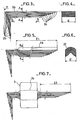
La figure 1 est une vue en coupe longitudinale, d'un circuit magnétique dont les bandes, de tôle, sont pliées pour fermeture sur l'aimant permanent, sans que soit, effectué, au préalable, un cambrage unitaire des bandes à un rayon R1.Figure 1 is a longitudinal sectional view of a magnetic circuit whose strips, of sheet metal, are folded for closure on the permanent magnet, without being carried out, beforehand, a unitary bending of the strips to a radius R1 .
La figure 2 est une vue en coupe longitudinale, d'un circuit magnétique dont les bandes, de tôle, sont selon le procédé de l'invention, cambrées unitairement à un rayon R1.Figure 2 is a longitudinal sectional view of a magnetic circuit whose strips, of sheet metal, are according to the method of the invention, individually bent at a radius R1.
La figure 3 est une vue longitudinale des bandes de tôle, préalablement cambrées unitairement à angle droit, à un rayon R1 et empilées les unes sur les autres de maniàre à constituer un paquet en forme de L.Figure 3 is a longitudinal view of the sheet metal strips, previously arched unitarily at right angles, to a radius R1 and stacked on each other so as to constitute an L-shaped package.
La figure 4 est une vue en coupe, suivant la ligne AA, des bandes, de tôle, constituant le paquet représenté par la figure 3.FIG. 4 is a sectional view, along the line AA, of strips, of sheet metal, constituting the package represented by FIG. 3.
La figure 5 est une vue longitudinale du paquet de bandes, de tôle, en forme de L dont l'une des branches est retrécie en largeur par un emboutissage selon une forme approximativement semicirculaire, sur une longueur 11.FIG. 5 is a longitudinal view of the packet of strips, of sheet metal, in the shape of an L, one of the branches of which is narrowed in width by a stamping in an approximately semicircular shape, over a length 11.
La figure 6 est une vue en coupe, suivant la ligne BB, du paquet de bandes, de tôle, représenté par la figure 5.FIG. 6 is a sectional view, along line BB, of the pack of strips, of sheet metal, represented by FIG. 5.
La figure 7 est une vue longitudinale du paquet de bandes, de tôle, ramené à sa largeur d'origine, sur une longueur 12, après mise en place du boîtier isolant contenant les enroulements primaire et secondaire.Figure 7 is a longitudinal view of the strip package, sheet, reduced to its original width, over a length 12, after installation of the insulating housing containing the primary and secondary windings.
La figure 8 est une vue longitudinale, en coupe partielle d'un premier mode de réalisation selon l'invention du dispositif de bridage du paquet de bondes, de tôle, sur l'aimant permanent.FIG. 8 is a longitudinal view, in partial section of a first embodiment according to the invention of the device for clamping the pack of bungs, of sheet metal, on the permanent magnet.
La figure 9 est une vue en coupe, selon la ligne CC, du dispositif de bridage représenté par la figure 8.FIG. 9 is a sectional view, along the line CC, of the clamping device represented by FIG. 8.
La figure 10 est la représentation du flanc de la pièce métallique constituant une partie du premier mode de réalisation du dispositif de bridage représenté par les figures 8 et 9.FIG. 10 is the representation of the side of the metal part constituting a part of the first embodiment of the clamping device represented by FIGS. 8 and 9.
La figure 11 est une représentation, en perspective partielle et à échelle réduite du dispositif de bridage correspondant aux figures 8, 9 et 10.FIG. 11 is a representation, in partial perspective and on a reduced scale, of the clamping device corresponding to FIGS. 8, 9 and 10.
La figure 12 est une représentation, en perspective partielle et à échelle réduite, d'une variante du premier mode de réalisation du dispositif de bridage.Figure 12 is a representation, in partial perspective and on a reduced scale, of a variant of the first embodiment of the clamping device.
La figure 13 est une représentation, en perspective partielle et à échelle réduite, d'un deuxième mode de réalisation du dispositif de bridage.Figure 13 is a representation, in partial perspective and on a reduced scale, of a second embodiment of the clamping device.
La figure 14 est une vue longitudinale partielle et à échelle réduite d'une variante du deuxième mode de réalisation du dispositif de bridage.Figure 14 is a partial longitudinal view on a reduced scale of a variant of the second embodiment of the clamping device.
Si pour des raisons de coût des outils de découpe des tôles, en forme de E, de L et de U, constituant un circuit magnétique tel que celui décrit dans la demande française de brevet n° de publication: 2486 160, on désire remplacer ce circuit par un circuit 1 obtenu, simplement, à partir de bandes 2 cisaillées à des longueurs différentes et empilées les unes sur les autres, circuit 1 dont l'une des branches, figure 1, est entourée par un boîtier isolant 3 dans lequel sont logés des enroulements primaire 4 et secondaire 5, on constate que la fermeture du circuit 1 sur les surfaces actives 51, Sl'de l'aimant perdre 20 -% de la surface du circuit en contact avec les surfaces actives S1, S1' par rapport au circuit en tôles découpées dont le périmètre et l'aimant permanent sont représentés en traits interrompus, figure 1. Cette perte qui influe défavorablement sur les performances de la bobine d'allumage est due au fait que la fermeture du circuit 1 sur les surfaces actives S1, S1' de l'aimant permanent 5, s'effectue par pliage selon des rayons R2 croissants depuis le périmètre intérieur jusqu'au périmètre extérieur.If, for cost reasons, sheet-cutting tools, in the form of E, L and U, constituting a magnetic circuit such as that described in French patent application publication no: 2486 160, we wish to replace this circuit by a
Conformément à la présente invention, la bobine d'allumage représentée par la figure 2, comprend un circuit magnétique 1, constitué de bandes 2, de tôle, dont l'une des branches est entourée par un boitier isolant 3 dans lesquels sont logés de enroulements primaire 4 et secondaire 5.According to the present invention, the ignition coil shown in Figure 2, comprises a
Selon le procédé de l'invention, et afin d'accroître la surface du circuit magnétique 1 en contact avec les surfoces actives S1, S1' de l'aimant permanent 6, les bandes 2 cisaillées à des longueurs différentes, sont préalablement combrées unitairement, à angle droit, à un rayon R1, de valeur 0,5 mm dans cet exemple de réalisation, et à une distance inégale de leurs extrémités figure 3, de manière qu'après empilage, les unes sur les autres, en un paquet 2a, de forme en L, les arêtes transversales 2b et 2c des bandes 2 soient respectivement situées sur des plans P et P' correspondants aux plans des surfaces actives S1 et 51' de l'aimant permanent 6. Selon un mode préféré de réalisation, 10 branche 2d, figure 5, du paquet 2a, est retrécie à une largeur E', sur une longueur 11, par un emboutissage selon une forme approximativement semi-circulaire 2f, figure 6, avant mise en place du boîtier isolant 3, laquelle branche 2d est ensuite ramenée à sa largeur d'origine E, sur une longueure 12, figure 7, après mise en place, sur la portion 2e, du boîtier isolant 3, dans lequel sont logés les enroulements primaire 4 et secondaire 5.According to the method of the invention, and in order to increase the surface of the
Après quoi le paquet 2a est conformé, par pliage, selon des rayons R2, de valeur 2 mm environ pour lepérimètre interne du circuit 1 et pour cet exemple de réalisation, lesquels rayons croissent depuis ce périmètre interne jusqu'au périmètre externe, figure 2, pour 10 fermeture du circuit 1 sur les surfaces actives S1 et S1' de l'aimant permanent 6.After which the
Selon un premier mode de réalisation, le dispositif de bridage 100, du paquet 2a sur l'aimant permanent 6 est constitué d'une bride 101, figures 8 et 9, laquelle bride 101 est obtenue par découpe d'un flanc 101 a dans une tôle d'acier doux, figure 10.:According to a first embodiment, the
La bride 101 comporte des ailes 101 b, figure 9, qui viennent en appui sur des ailes 104a de ploquettes isolantes 104 intercalées entre les foces latérales du paquet 2a et de l'aimant permanent 6, dont le maintien à l'intérieur de la bride 101 est obtenu par la formation préalable d'une charnière 101c qu'on referme par pression dans le sens des flèches F, à l'aide de tous moyens connus. La bride 101, comporte des pattes 101d et 101e, obtenues lors de la découpe du flonc 101a, figure 10, lesquelles pattes, après des opérations successives de rabattement se présentent parallèlement à la face externe 101f de la bride 101, figures 8 et 9, de façon que des échancrures 101g et 101h et un bord latéral 101j ménagés dans les pattes 101d et 101e, figure 10, forment des ouvertures 101 k et 1011 perpendiculaires entre elles, figures 11, pour la fixation de la bobine d'allumage sur le véhicule automobile.The
Selon une variante du premier mode de réalisation du dispositif de bridage 100, la bride 101, comporte des excroissances 101m et 101n représentées sur la figure 10 en traits interrompus, l'excroissonce 101 m comporte un trou lisse 101 p dans lequel s'engage une vis 110, figure 12, l'excroissance 101 comportant un trou fileté 101 q, figure 10, dans lequel vient se visser la vis 110, figure 12, de manière à renfocer le maintien du paquet 2a et de l'aimant permanent 6 à l'intérieur de la bride 101.According to a variant of the first embodiment of the
Selon un deuxième mode de réalisation, le dispositif de bridage 100, est consitué de demi-brides 120 qui comportent des pattes 120a, de fixation de la bobine d'allumage sur le véhicule automobile.According to a second embodiment, the
Les demi-brides 120 comportent des ailes 120b et 120c qui enserrent le paquet 2a et l'aimant permanent 6, par l'intermédiaire de plaquettes isolantes 121, disposées de manière identique au plaquettes isolantes 104 du premier mode de réalisation du dispositif de bridage.The half-
Les demi-brides 120 sont solidarisées entre elles à l'aide de vis 122, l'une des demi-brides comportant des trous lisses l'autre comportant des trous filetés.The half-
Selon une variante du deuxième mode de réalisation du dispositif de bridage, l'aimant permanent 6 est constitué de deux parties 6a, 6b, entre lesquelles est ménagé un espace dans lequel pénètre une vis 130 assurant la solidarisation des demi-brides 120.According to a variant of the second embodiment of the clamping device, the
Les brides métalliques 101 et 120, ainsi que les plaquettes isolantes 104 et 121, de la présente invention constituent avantageusement un circuit de dérivation du flux magnétique crée par l'enroulement primaire 4, circuit de dérivation décrit dans la demande française de brevet n° de publication 2 486 160.The
Claims (7)
Applications Claiming Priority (2)
| Application Number | Priority Date | Filing Date | Title |
|---|---|---|---|
| FR8213966A FR2531752A1 (en) | 1982-08-11 | 1982-08-11 | PROCESS FOR OBTAINING A COIL WITH A CLOSED MAGNETIC CIRCUIT AND A PERMANENT MAGNET FOR THE IGNITION OF INTERNAL COMBUSTION ENGINES |
| FR8213966 | 1982-08-11 |
Publications (2)
| Publication Number | Publication Date |
|---|---|
| EP0102261A1 EP0102261A1 (en) | 1984-03-07 |
| EP0102261B1 true EP0102261B1 (en) | 1986-11-05 |
Family
ID=9276797
Family Applications (1)
| Application Number | Title | Priority Date | Filing Date |
|---|---|---|---|
| EP19830401361 Expired EP0102261B1 (en) | 1982-08-11 | 1983-07-01 | Method of obtaining a coil with a closed magnetic circuit and a permanent magnet for the ignition of combustion engines |
Country Status (4)
| Country | Link |
|---|---|
| EP (1) | EP0102261B1 (en) |
| DE (1) | DE3367480D1 (en) |
| ES (1) | ES524494A0 (en) |
| FR (1) | FR2531752A1 (en) |
Families Citing this family (2)
| Publication number | Priority date | Publication date | Assignee | Title |
|---|---|---|---|---|
| DE3505367A1 (en) * | 1985-02-15 | 1986-08-28 | Daimler-Benz Ag, 7000 Stuttgart | IGNITION COIL FOR INTERNAL COMBUSTION ENGINES |
| US4857878A (en) * | 1988-01-19 | 1989-08-15 | Eng Jr Benjamin | Modular high frequency power transformer |
Family Cites Families (9)
| Publication number | Priority date | Publication date | Assignee | Title |
|---|---|---|---|---|
| US1557501A (en) * | 1923-07-17 | 1925-10-13 | Gen Motors Corp | Ignition coil |
| US2878855A (en) * | 1954-05-12 | 1959-03-24 | Kuhlman Electric Company | Mandrel for forming laminated transformer core |
| DE1464202A1 (en) * | 1962-02-23 | 1969-05-22 | Licentia Gmbh | Permanently biased inductive element |
| CH416817A (en) * | 1964-06-17 | 1966-07-15 | Breitmeier Max | Magnetic core, especially for transformers or chokes |
| FR1482818A (en) * | 1964-09-08 | 1967-06-02 | Csf | Development of ignition coils for combustion engines |
| FR1463890A (en) * | 1965-09-20 | 1966-07-22 | Gen Electric | Preformed magnetic core structure |
| FR1533644A (en) * | 1967-08-04 | 1968-07-19 | Lucas Industries Ltd | Laminated core, in particular for ignition coil and its manufacturing process |
| IE34523B1 (en) * | 1970-11-14 | 1975-05-28 | Slade Components Ltd | Construction of choke |
| FR2511184A1 (en) * | 1981-08-06 | 1983-02-11 | Ducellier & Cie | PROCESS FOR OBTAINING A COIL WITH A CLOSED MAGNETIC CIRCUIT AND A PERMANENT MAGNET FOR THE IGNITION OF AN INTERNAL COMBUSTION ENGINE |
-
1982
- 1982-08-11 FR FR8213966A patent/FR2531752A1/en active Granted
-
1983
- 1983-07-01 EP EP19830401361 patent/EP0102261B1/en not_active Expired
- 1983-07-01 DE DE8383401361T patent/DE3367480D1/en not_active Expired
- 1983-07-28 ES ES524494A patent/ES524494A0/en active Granted
Also Published As
| Publication number | Publication date |
|---|---|
| EP0102261A1 (en) | 1984-03-07 |
| ES8404016A1 (en) | 1984-04-16 |
| DE3367480D1 (en) | 1986-12-11 |
| FR2531752B1 (en) | 1985-01-04 |
| ES524494A0 (en) | 1984-04-16 |
| FR2531752A1 (en) | 1984-02-17 |
Similar Documents
| Publication | Publication Date | Title |
|---|---|---|
| FR2556146A1 (en) | Device for mounting and insulating conductors on the rotors of electric rotating machines | |
| FR2619256A1 (en) | ELECTRIC CONTACT TERMINAL AND METHOD FOR MANUFACTURING SUCH A TERMINAL | |
| EP0102261B1 (en) | Method of obtaining a coil with a closed magnetic circuit and a permanent magnet for the ignition of combustion engines | |
| FR2531751A1 (en) | IGNITION COIL FOR INTERNAL COMBUSTION ENGINE | |
| EP0805329A1 (en) | Heat exchanger with a tubular header box and fastening element | |
| EP0028951A2 (en) | Heat exchanger comprising a bundle of tubes opening into collector panels mechanically associated with water vessels | |
| EP0511061B1 (en) | Plastic objject with alignment inserts | |
| JPH0524361B2 (en) | ||
| FR2792118A1 (en) | METHOD AND DEVICE FOR INTERCONNECTING TERMINALS | |
| EP0202144A1 (en) | Electromagnetic sealing element of the knife-contact type | |
| EP0751540B1 (en) | Bobbin for transformer and transformer having such a bobbin | |
| EP0708303A1 (en) | Heat exchanger having a tube bundle and a metallic leader box | |
| EP0072266B1 (en) | Method of obtaining a coil with a closed magnetic circuit and a permanent magnet for the ignition of combustion engines | |
| EP0143023A1 (en) | Casing for the magnetic circuit of ignition transformers for vehicles and method for manufacturing the same | |
| EP0746692B1 (en) | Clip device for fastening an element to a sheet metal portion of a motor vehicle, and method for making same | |
| FR2734016A1 (en) | Adjustable door stop for motor vehicle | |
| FR2690011A1 (en) | Electrical connection terminal for connecting wire to conducting chamber of electrical appts. - has flat cap conductor and tightening screw which immobilises conductors against its extremities which are approximately parallel | |
| FR2527709A1 (en) | COUPLING COLLAR MADE BY STAMPING AND FOLDING A BLANK | |
| FR2512765A1 (en) | Bonnet catch for motor vehicle - has retaining plate to hold legs of sprung steel hook | |
| FR2507393A1 (en) | Self-insulation-stripping connector terminal for single wires - has grooved folded blade which strips and grips conductor and severs end | |
| FR2568426A1 (en) | ROTARY ELECTRIC MACHINE INDUCTOR COIL ASSEMBLY. | |
| FR2585412A1 (en) | Ignition coil casing for an internal combustion engine | |
| FR2508715A1 (en) | Screw tightenable electrical terminal connector - has base and screw within tube and unitary with base having central opening allowing passage of wire | |
| FR2736202A1 (en) | Clip holder for fuse with offset fixing holes on attached plate, e.g. for transformer | |
| EP1273810B1 (en) | Blind fastening clip and method of instalation |
Legal Events
| Date | Code | Title | Description |
|---|---|---|---|
| PUAI | Public reference made under article 153(3) epc to a published international application that has entered the european phase |
Free format text: ORIGINAL CODE: 0009012 |
|
| AK | Designated contracting states |
Designated state(s): DE GB IT |
|
| 17P | Request for examination filed |
Effective date: 19840517 |
|
| GRAA | (expected) grant |
Free format text: ORIGINAL CODE: 0009210 |
|
| AK | Designated contracting states |
Kind code of ref document: B1 Designated state(s): DE GB IT |
|
| ITF | It: translation for a ep patent filed | ||
| REF | Corresponds to: |
Ref document number: 3367480 Country of ref document: DE Date of ref document: 19861211 |
|
| PLBE | No opposition filed within time limit |
Free format text: ORIGINAL CODE: 0009261 |
|
| STAA | Information on the status of an ep patent application or granted ep patent |
Free format text: STATUS: NO OPPOSITION FILED WITHIN TIME LIMIT |
|
| 26N | No opposition filed | ||
| PG25 | Lapsed in a contracting state [announced via postgrant information from national office to epo] |
Ref country code: GB Effective date: 19890701 |
|
| GBPC | Gb: european patent ceased through non-payment of renewal fee | ||
| PG25 | Lapsed in a contracting state [announced via postgrant information from national office to epo] |
Ref country code: DE Effective date: 19900403 |