EP0102246B1 - Containment and densification of particulate material - Google Patents
Containment and densification of particulate material Download PDFInfo
- Publication number
- EP0102246B1 EP0102246B1 EP19830304974 EP83304974A EP0102246B1 EP 0102246 B1 EP0102246 B1 EP 0102246B1 EP 19830304974 EP19830304974 EP 19830304974 EP 83304974 A EP83304974 A EP 83304974A EP 0102246 B1 EP0102246 B1 EP 0102246B1
- Authority
- EP
- European Patent Office
- Prior art keywords
- bellows
- container
- bellows container
- canister
- refractory
- Prior art date
- Legal status (The legal status is an assumption and is not a legal conclusion. Google has not performed a legal analysis and makes no representation as to the accuracy of the status listed.)
- Expired
Links
- 238000000280 densification Methods 0.000 title claims description 21
- 239000011236 particulate material Substances 0.000 title claims description 8
- 238000000034 method Methods 0.000 claims description 41
- 239000000463 material Substances 0.000 claims description 29
- 238000003825 pressing Methods 0.000 claims description 24
- 239000011435 rock Substances 0.000 claims description 23
- 238000010438 heat treatment Methods 0.000 claims description 21
- 230000006698 induction Effects 0.000 claims description 15
- 238000007906 compression Methods 0.000 claims description 14
- 230000006835 compression Effects 0.000 claims description 14
- 230000015572 biosynthetic process Effects 0.000 claims description 8
- 238000007731 hot pressing Methods 0.000 claims description 8
- 239000002901 radioactive waste Substances 0.000 claims description 8
- 238000003860 storage Methods 0.000 claims description 8
- 239000002243 precursor Substances 0.000 claims description 7
- 239000002002 slurry Substances 0.000 claims description 6
- 229910052751 metal Inorganic materials 0.000 claims description 4
- 239000002184 metal Substances 0.000 claims description 4
- 239000002245 particle Substances 0.000 claims description 3
- 239000011819 refractory material Substances 0.000 claims description 3
- 238000007789 sealing Methods 0.000 claims description 3
- 230000009471 action Effects 0.000 claims description 2
- 238000005507 spraying Methods 0.000 claims description 2
- 238000005192 partition Methods 0.000 claims 3
- 239000002699 waste material Substances 0.000 description 19
- 230000008569 process Effects 0.000 description 11
- 239000002927 high level radioactive waste Substances 0.000 description 7
- 230000002285 radioactive effect Effects 0.000 description 6
- XLYOFNOQVPJJNP-UHFFFAOYSA-N water Substances O XLYOFNOQVPJJNP-UHFFFAOYSA-N 0.000 description 6
- 229910000831 Steel Inorganic materials 0.000 description 4
- 230000008901 benefit Effects 0.000 description 4
- 230000007774 longterm Effects 0.000 description 4
- 238000002156 mixing Methods 0.000 description 4
- 239000000203 mixture Substances 0.000 description 4
- 239000000243 solution Substances 0.000 description 4
- 239000010959 steel Substances 0.000 description 4
- 229910002651 NO3 Inorganic materials 0.000 description 3
- HEMHJVSKTPXQMS-UHFFFAOYSA-M Sodium hydroxide Chemical compound [OH-].[Na+] HEMHJVSKTPXQMS-UHFFFAOYSA-M 0.000 description 3
- RTAQQCXQSZGOHL-UHFFFAOYSA-N Titanium Chemical compound [Ti] RTAQQCXQSZGOHL-UHFFFAOYSA-N 0.000 description 3
- 239000007789 gas Substances 0.000 description 3
- 229910052500 inorganic mineral Inorganic materials 0.000 description 3
- 239000011707 mineral Substances 0.000 description 3
- 239000000843 powder Substances 0.000 description 3
- NHNBFGGVMKEFGY-UHFFFAOYSA-N Nitrate Chemical compound [O-][N+]([O-])=O NHNBFGGVMKEFGY-UHFFFAOYSA-N 0.000 description 2
- 239000000470 constituent Substances 0.000 description 2
- 238000011161 development Methods 0.000 description 2
- 230000018109 developmental process Effects 0.000 description 2
- 239000001257 hydrogen Substances 0.000 description 2
- 229910052739 hydrogen Inorganic materials 0.000 description 2
- 238000002386 leaching Methods 0.000 description 2
- 230000033001 locomotion Effects 0.000 description 2
- 150000002823 nitrates Chemical class 0.000 description 2
- 239000006104 solid solution Substances 0.000 description 2
- 229910001220 stainless steel Inorganic materials 0.000 description 2
- 239000010935 stainless steel Substances 0.000 description 2
- 229910052719 titanium Inorganic materials 0.000 description 2
- 239000010936 titanium Substances 0.000 description 2
- VXUYXOFXAQZZMF-UHFFFAOYSA-N titanium(IV) isopropoxide Chemical compound CC(C)O[Ti](OC(C)C)(OC(C)C)OC(C)C VXUYXOFXAQZZMF-UHFFFAOYSA-N 0.000 description 2
- 229910001093 Zr alloy Inorganic materials 0.000 description 1
- 239000000654 additive Substances 0.000 description 1
- QVGXLLKOCUKJST-UHFFFAOYSA-N atomic oxygen Chemical compound [O] QVGXLLKOCUKJST-UHFFFAOYSA-N 0.000 description 1
- 229910000963 austenitic stainless steel Inorganic materials 0.000 description 1
- 239000005388 borosilicate glass Substances 0.000 description 1
- BSDOQSMQCZQLDV-UHFFFAOYSA-N butan-1-olate;zirconium(4+) Chemical compound [Zr+4].CCCC[O-].CCCC[O-].CCCC[O-].CCCC[O-] BSDOQSMQCZQLDV-UHFFFAOYSA-N 0.000 description 1
- 238000002144 chemical decomposition reaction Methods 0.000 description 1
- 238000005056 compaction Methods 0.000 description 1
- 239000013078 crystal Substances 0.000 description 1
- 238000013461 design Methods 0.000 description 1
- 238000004031 devitrification Methods 0.000 description 1
- 239000010419 fine particle Substances 0.000 description 1
- 239000011521 glass Substances 0.000 description 1
- 230000005484 gravity Effects 0.000 description 1
- 230000003100 immobilizing effect Effects 0.000 description 1
- 230000006872 improvement Effects 0.000 description 1
- 238000010348 incorporation Methods 0.000 description 1
- 238000005342 ion exchange Methods 0.000 description 1
- 238000012423 maintenance Methods 0.000 description 1
- 238000004519 manufacturing process Methods 0.000 description 1
- 239000003758 nuclear fuel Substances 0.000 description 1
- 239000001301 oxygen Substances 0.000 description 1
- 229910052760 oxygen Inorganic materials 0.000 description 1
- RVTZCBVAJQQJTK-UHFFFAOYSA-N oxygen(2-);zirconium(4+) Chemical compound [O-2].[O-2].[Zr+4] RVTZCBVAJQQJTK-UHFFFAOYSA-N 0.000 description 1
- 239000007787 solid Substances 0.000 description 1
- 239000011343 solid material Substances 0.000 description 1
- 239000000126 substance Substances 0.000 description 1
- 239000011885 synergistic combination Substances 0.000 description 1
- 229910001928 zirconium oxide Inorganic materials 0.000 description 1
Images




Classifications
-
- G—PHYSICS
- G21—NUCLEAR PHYSICS; NUCLEAR ENGINEERING
- G21F—PROTECTION AGAINST X-RADIATION, GAMMA RADIATION, CORPUSCULAR RADIATION OR PARTICLE BOMBARDMENT; TREATING RADIOACTIVELY CONTAMINATED MATERIAL; DECONTAMINATION ARRANGEMENTS THEREFOR
- G21F9/00—Treating radioactively contaminated material; Decontamination arrangements therefor
- G21F9/28—Treating solids
- G21F9/34—Disposal of solid waste
Definitions
- the nuclear reactor waste is incorporated into the crystal lattices of the synthetic rock in the form of a dilute solid solution and therefore should be safely immobilised.
- a dense, compact, mechanically strong block of the synthetic rock incorporating the nuclear waste is produced by pressure and heat in a densification process and the block may then be safely disposed of in a suitable geological formation.
- the high working temperatures for the densification step are best achieved by the use of induction heating and therefore typically it takes many hours for the contents of the bellows container to come to a uniform working temperature. Therefore preheating of the bellows container to bring the contents up to a uniform temperature suitable for the densification step is a major advantage. Not only can the production rate for given capital cost be maximized but furthermore a substantial further advantage is that bringing the contents of the bellows container to the uniform densification temperature aids reliable and uniform densification thereby ensuring reliable axial compression of the bellows container which facilitates its later handling and storage.
- the bellows container is typically of a heat resistant steel and preferably a stainless steel. Inevitably the mechanical strength of the steel is reduced at the high densification temperatures in the region of 1100 to 1200°C.
- Such a method may be defined as consisting in a method for the containment of particulate waste material, the method comprising pouring the waste material into bellows containers of generally cylindrical form with a side wall including a bellows-like formation and of heat and decay resistant material, closing each bellows container with a lid, preheating in series the bellows containers to bring the contents thereof to a substantially uniform elevated temperature, placing each bellows container in turn on an upwardly displaceable ram and displacing the ram upwardly to insert the bellows container into a cylindrical canister and applying pressure and maintaining a sufficiently elevated temperature for sufficient time to cause densification of the contents of the bellows container with axial compression of the bellows container and relatively slight outward expansion thereof to cause the bellows container to grip the interior wall of the cylindrical canister, and when the canister has been filled with a series of such bellows containers, sealing the canister and removing the canister for storage.
- the invention is particularly useful in relation to the incorporation of high level radioactive waste in synthetic rock of the type described by A. E. Ringwood (and referred to above), the invention can also be applied to other synthetic rock arrangements and furthermore can also be applicable to other materials which require storage and are capable of compaction under heat and pressure.
- One example of such other material would be shredded waste zirconium alloy nuclear fuel rod tubes and similar waste components.
- the invention consists in a combination of steps which cooperate together in an advantageous relationship which permits efficient, economic, and convenient operations in a hot cell.
- the apparatus used can be relatively simple, and this can contribute greatly to the reliability and acceptability of the system due to simplicity of servicing and intrinsic reliability.
- the material is preferably provided in the form of well graded fine particles up to about 2 mm maximum dimension whereby a readily pourable material is provided which can be easily densified in the process.
- a preferred embodiment of the invention can also provide further means for safeguarding the cylindrical canister from outward deformation under the pressure of expanding bellows containers within the canister.
- This is achievable by the use of a block of refractory material having a slightly tapered bore which at its narrowest diameter just fits over the canister, the refractory block being adapted to be moved downwardly in a series of steps corresponding to bellows container locations, the slightly tapered bores permitting release of the block even if some outward deformation of the canister has taken place in a step of densification and compression of the bellows container.
- the refractory block is formed so as to embrace the induction heating coil for surrounding the canister.
- the refractory block comprises a series of interlocking refractory segments arranged to be mounted inside a cylindrical containment shroud which absorbs any expansion forces applied from the canister.
- apparatus for encapsulating particulate supply material in bellows containers within a cylindrical canister comprising means for pouring the particulate material into a bellows container, means for sealing the bellows container with a lid, means for moving bellows containers in sequence to a pressing station at which the container is heated and axial pressure is applied to the container causing the axial compression of the container, characterized in that said pressing station comprising an upwardly displaceable ram for receiving a bellows container, means for mounting a cylindrical canister with an open end directed downwardly towards said ram, means for upwardly pressing a bellows container supported on the ram into the canister, upper refractory support means to act as a fixed abutment for the canister and the bellows container pressed upwardly therein by said ram, heating means for maintaining an elevated temperature in said bellows container whilst said pressure is applied to cause densification of said supply material in the bellows container and to expand slightly the bell
- the process has a preliminary mixing stage 21 in which synthetic rock precursor from supply 20 is formed into a slurry with high level radioactive waste from waste supply 19 which is in the form of a nitrate solution, and the slurry is passed along line 22 to be sprayed into the elevated temperature end of a rotary kiln, at which a maximum temperature in the range 700-800 0 is maintained.
- the spraying step immediately vaporises the water content of the slurry sprayed into the rotary kiln and causes chemical decomposition of the radioactive nitrates and will cause the mineral components of the synthetic rock to start to form with the radioactive elements starting to go into mineral phases.
- the particulate material produced by the rotary kiln is fed into a titanium mixing stage 24 which receives metallic titanium powder from a hopper 25 whereby the mixture poured into a bellows container 20 has about 2% titanium metal powder by weight.
- the precursor material is a product which possesses a very high surface area and functions as an effective ion exchange medium, which is mixed with additives containing Ca, Ba, and AI in solution and mixed in a hot cell with high level nuclear waste (HLW) in the form of nitrate solution to form a thick homogeneous slurry at mixing stage 21.
- HMW high level nuclear waste
- up to about 20% by weight of the solid content of the slurry may comprise the high level wastes.
- the bellows container 20 is of a heat resisting steel such as an austenitic stainless steel, for example Sandvik grade 253MA which retains reasonable mechanical strength even at the elevated temperatures used in the process, although at these temperatures the container is relatively ductile.
- a thin perforated metal liner 26 is located within the bellows container and the space between the liner and bellows wall is filled with zirconium oxide powder 27.
- a stainless steel cap 29 is used to seal the bellows container which is then placed between a pair of pistons 30 for a cold pressing operation which can increase the density of particulate material from about 25% of the theoretical maximum density to about 36%.
- each bellows container 20 is fed in sequence into a vertical induction furnace 31, each bellows container being supported on a refractory disk 32, the lowermost refractory disk being supported by a retractable latch 33. Over a period of several hours the temperature gradually increases up to about 1200°C.
- a first water cooled ram 34 having a top spigot on which a refractory plate 35 is located is adapted to support and lower one at a time the bellows containers from the furnace for horizontal movement across a support table 36 to a pressing station having a second water cooled ram 37 of similar form.
- Figure 2 shows the ram 37 both in the lower receiving position and also in the upwardly displaced pressing position inside a metal canister 38 mounted on a support 39 and having its top sealed and in abutment against a fixed refractory block 40, vertically displaceable induction heating coils 41 being provided outside the canister 38.
- the left hand side of the section of a bellows container 20a is shown in its configuration before hot pressing and the right hand side of the section shows a bellows container 20b as it would be after pressing.
- the bellows container slightly expands to become an interference fit within the canister 38 as shown by bellows 20c at the top of the canister 38.
- the refractory plate 32 upon which each of the bellows containers is supported is removed after the pressing stage, the plate 32 being lowered on the water cooled ram 37 and then pushed onto a receiving table from which the plate can be recycled for further use.
- Refractory plates will wear in use and must be replaced and an important advantage of the design illustrated in Figure 2 is a very simple and easily serviced arrangement made possible by the use of an upward pressing technique; this permits the replaceable refractory top plate 35 simply to sit on the head of each water cooled ram. Just a simple spigot and socket engagement is provided so that manipulators can readily remove a worn refractory plate and insert a new one.
- the apparatus further includes a base plate 42 with a set of upstanding tubular guides 43 on which sliding mounts for the support 39 and the induction furnace unit 41 are slidably mounted but adapted to be clamped at any selected position.
- the canister 38 is urged upwardly against the refractory block 40 which is supported by a top cap 44 adapted to be bolted to a top plate 45.
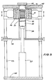
- Figure 3 shows the parts in slightly exploded view for clarity.
- the induction heating coil 41 is shown embedded within a refractory block 46 having a tapered bore, the drawing showing a greatly exaggerated taper and clearance between the bore and the container 38.
- the object of the tapered bore of the refractory block 46 is that any small expansion of the canister 38 causes the canister to be supported against further outward deformation by the refractory block but by virtue of the taper the refractory block can be released by downward motion to the next location for the succeeding bellows container.
- the refractory block is assembled from refractory segments comprising outer refractory segments 46a of cylindrical profile and inner refractory elements 46b having an inner profile adapted to cooperate to form a tapered bore with circumferentially extending grooves for accommodating the turns of the induction coil 41.
- the refractory elements are contained within a steel outer support cylinder 47 which absorbs the forces of any outward expansion applied by the canister 38.
- Figure 5 shows in isometric view the refractory blocks 46a and 46b each having a semi-circular rib 46c on one side thereof and a corresponding cavity 46d on the other side for interengagement purposes.
Landscapes
- Engineering & Computer Science (AREA)
- Environmental & Geological Engineering (AREA)
- Physics & Mathematics (AREA)
- General Engineering & Computer Science (AREA)
- High Energy & Nuclear Physics (AREA)
- Processing Of Solid Wastes (AREA)
Description
- The present invention relates to the containment of waste material, and more particularly is concerned with arrangements for containing waste material which requires very reliable, very long term storage.
- Extremely long term safe storage of nuclear wastes is a major problem for the nuclear industry and various proposals have been made for dealing with this problem. One proposal concerns immobilising the waste in a suitable borosilicate glass which can then be deposited in a suitable geological formation. However, doubts concerning possible devitrification of the glass and consequent leaching of radioactive elements have founded criticism of the safety of this technique.
- Another recent proposal involves the formation of a synthetic rock in which the nuclear reactor waste is immobilised, details of this method being described by A. E. Ringwood et al in Nature March 1979. According to the disclosure, a selected synthetic rock is formed with the radioactive elements in solid solution. The constituent minerals of the rock or close structural analogues have survived in a wide range of geochemical environments for millions of years and are considered highly resistant to leaching by water.
- The nuclear reactor waste is incorporated into the crystal lattices of the synthetic rock in the form of a dilute solid solution and therefore should be safely immobilised. A dense, compact, mechanically strong block of the synthetic rock incorporating the nuclear waste is produced by pressure and heat in a densification process and the block may then be safely disposed of in a suitable geological formation.
- The following patent applications have been filed by the Australian National University based on the work by A. E. Ringwood et al:-
- Australian Patent Application 48708/79 (now Patent AU-A-523,472) entitled "Safe Immobilisation of High Level Nuclear Reactor Waste"; and
- United States Patent Application 124953 (now Patent US-A-4,329,248) entitled "A Proces for the Treatment of High Level Nuclear Wastes".
- A further development in the field is disclosed in Australian Patent Specification 65176/80 (now Patent AU-A-531250) which is concerned with apparatus and method for immobilising waste material and is directed to selected methods for providing a containment arrangement which will provide a very high degree of safeguarding of the synthetic rock incorporating radioactive waste while nevertheless being produced in a process which is operable within the confines and limitations of a "hot ceti". High level radioactive waste must be handled in a hot cell in which all operations are conducted automatically or by an operator using manipulators, and since the apparatus used will inevitably become contaminated itself, the apparatus should be of a form which facilitates servicing within the hot cell and ultimately disposal when its useful working life has come to an end.
- Yet further developments in this field are disclosed in European Patent Application 0,044,692 in which additional apparatus and methods for immobilizing waste material such as high level radioactive waste in synthetic rock is disclosed. Among the configurations described is a method in which a powder comprising the synthetic rock materials intimately mixed with the radioactive waste is filled into a container having a bellows-like wall structure and after the container is closed, it is located inside an outer canister around which an induction heating coil is placed. A downwardly acting ram then applies pressure for sufficient time to cause densification of the contents of the bellows container. A series of bellows containers are adapted to be stacked in the outer canister which, when full, is then sealed and removed to a safe storage location.
- Despite these various proposals, it is still considered that there is a need to conceive of a more effective, practical and,'most importantly, reliable arrangement capable of convenient use in a hot cell.
- Broadly, the present invention provides a method of containing and densifying particulate supply material comprising radioactive waste and synthetic rock precursor material, the method comprising pouring the supply material into a bellows container of generally cylindrical form with a side wall including a bellows-like formation and of heat and decay resistant material, closing the bellows container with a lid, placing the bellows container on an upwardly displaceable ram having a heat resistant surface portion, maintaining substantially axial pressure on the bellows container, applying heat and maintaining a sufficiently elevated temperature in the bellows container for a sufficient length of time to cause densification of said particulate supply material in the bellows container and axial compression of the bellows container, the arrangement being such that deformation of the bellows container occurs in its axial direction, and removing the bellows container after completion of the densification step characterized in that said pressure is applied substantially axially to the bellows container solely by the action of an upwardly acting ram which presses the container against a fixed abutment with the bellows-like formation free of surrounding support.
- The invention thus can provide a most effective and reliable process for use with supply material in the form of high level radioactive waste and capable of long term operation in a hot cell with ease of operation of the process and maintenance of equipment. Furthermore, the method characterised by the upward pressing technique permits considerable economy of capital equipment and the hot cell space required by virtue of the use of a single ram with a fixed abutment. Since typically operating temperatures in the region of 1100°C will be used, a substantial refractory facing can readily be provided for the fixed abutment and also for the refractory ram. The upward pressing method facilitates, in a preferred embodiment, a most easily serviced apparatus since the refractory facing for the ram can simply be a disc-like pad located by simple locating means such as a spigot and socket with the pad essentially remaining in position under the force of gravity. Thus, using manipulators in a hot cell a worn refractory pad can readily be removed for disposal and a replacement pad fitted.
- Furthermore, a major improvement in the process can occur when the broad method described above is used in combination with a preheating step substantially without the application of pressure.
- The high working temperatures for the densification step are best achieved by the use of induction heating and therefore typically it takes many hours for the contents of the bellows container to come to a uniform working temperature. Therefore preheating of the bellows container to bring the contents up to a uniform temperature suitable for the densification step is a major advantage. Not only can the production rate for given capital cost be maximized but furthermore a substantial further advantage is that bringing the contents of the bellows container to the uniform densification temperature aids reliable and uniform densification thereby ensuring reliable axial compression of the bellows container which facilitates its later handling and storage. It is to be noted that the bellows container is typically of a heat resistant steel and preferably a stainless steel. Inevitably the mechanical strength of the steel is reduced at the high densification temperatures in the region of 1100 to 1200°C.
- Furthermore, the broad method may be utilized in a surprisingly effective and synergistic combination of steps in which the bellows container is subjected to the densification step whilst in a cylindrical canister in which the bellows container becomes a tight fit after the pressing operation thereby providing a most effective and convenient extra containment for long term safe storage of the waste material. Such a method may be defined as consisting in a method for the containment of particulate waste material, the method comprising pouring the waste material into bellows containers of generally cylindrical form with a side wall including a bellows-like formation and of heat and decay resistant material, closing each bellows container with a lid, preheating in series the bellows containers to bring the contents thereof to a substantially uniform elevated temperature, placing each bellows container in turn on an upwardly displaceable ram and displacing the ram upwardly to insert the bellows container into a cylindrical canister and applying pressure and maintaining a sufficiently elevated temperature for sufficient time to cause densification of the contents of the bellows container with axial compression of the bellows container and relatively slight outward expansion thereof to cause the bellows container to grip the interior wall of the cylindrical canister, and when the canister has been filled with a series of such bellows containers, sealing the canister and removing the canister for storage.
- Whilst the invention is particularly useful in relation to the incorporation of high level radioactive waste in synthetic rock of the type described by A. E. Ringwood (and referred to above), the invention can also be applied to other synthetic rock arrangements and furthermore can also be applicable to other materials which require storage and are capable of compaction under heat and pressure. One example of such other material would be shredded waste zirconium alloy nuclear fuel rod tubes and similar waste components.
- It will be appreciated that the invention consists in a combination of steps which cooperate together in an advantageous relationship which permits efficient, economic, and convenient operations in a hot cell. The apparatus used can be relatively simple, and this can contribute greatly to the reliability and acceptability of the system due to simplicity of servicing and intrinsic reliability.
- In a commercial scale operation, it is envisaged that the cylindrical canister will be of the order of 30 cm diameter and 2 metres long and each bellows container will be compressible from an initial height of about 40 cm to a final height of about 10 cm. The use of induction heating coils is the preferred method of both preheating and maintaining the necessary elevated temperature during the densification step, and due to the fact that heating of the 5 particulate material is due to conduction from the bellows container (which is heated by the induction heating coils) a considerable time is required for the preheating step. In a preferred embodiment of the invention, preheating for several hours can be effective whereas the final densification step will be much shorter, e.g. about one hour.
- Most preferably, the bellows container is given a preliminary axial pressing which can be at ambient temperature or with advantage can be at a bellows container temperature of up to about 800°C to anneal the material of the bellows container. Since the bellows container will have a high degree of strength at ambient temperature and also at temperatures up to about 800°C, good control can be achieved in this preliminary axial pressing and, surprisingly, during the densification step at high temperature (typically 1200°C) excellent control of the axial pressing can be achieved thereby essentially minimizing the risk of the bellows container compressing with sideways shear rather than true axial compression.
- Preferably, the pressure in the preliminary pressing is of at least (3000 Ibs/sq. inch) 20,68· 10°` Pa.
- Particularly when synthetic rock is to be formed, the material is preferably provided in the form of well graded fine particles up to about 2 mm maximum dimension whereby a readily pourable material is provided which can be easily densified in the process.
- Preferably synthetic rock is used to incorporate radioactive waste, a mixture of synthetic rock precursor and high level waste being sprayed into a rotary kiln to produce the intimately mixed materials. In order to reduce what would otherwise be loss from the solid material of potentially volatile radioactive components, the temperature at the region in which the material is introduced into the rotary kiln is preferably controlled in the range of about 400―600°C, and the maximum temperature in the kiln is about 700-800°C with the exit from the rotary kiln being at ambient temperature.
- A preferred embodiment of the invention can also provide further means for safeguarding the cylindrical canister from outward deformation under the pressure of expanding bellows containers within the canister. This is achievable by the use of a block of refractory material having a slightly tapered bore which at its narrowest diameter just fits over the canister, the refractory block being adapted to be moved downwardly in a series of steps corresponding to bellows container locations, the slightly tapered bores permitting release of the block even if some outward deformation of the canister has taken place in a step of densification and compression of the bellows container.
- Most preferably, the refractory block is formed so as to embrace the induction heating coil for surrounding the canister.
- Most preferably, the refractory block comprises a series of interlocking refractory segments arranged to be mounted inside a cylindrical containment shroud which absorbs any expansion forces applied from the canister.
- According to a second aspect of the invention, there is provided apparatus for encapsulating particulate supply material in bellows containers within a cylindrical canister, the apparatus comprising means for pouring the particulate material into a bellows container, means for sealing the bellows container with a lid, means for moving bellows containers in sequence to a pressing station at which the container is heated and axial pressure is applied to the container causing the axial compression of the container, characterized in that said pressing station comprising an upwardly displaceable ram for receiving a bellows container, means for mounting a cylindrical canister with an open end directed downwardly towards said ram, means for upwardly pressing a bellows container supported on the ram into the canister, upper refractory support means to act as a fixed abutment for the canister and the bellows container pressed upwardly therein by said ram, heating means for maintaining an elevated temperature in said bellows container whilst said pressure is applied to cause densification of said supply material in the bellows container and to expand slightly the bellows container to cause it to jam in the canister, and the heating means being adapted to provide heating in a series of zones within the container corresponding to a series of bellows containers inserted one below the other in series therein, the canister being adapted by being removed and sealed when a series of bellows containers have been densified and secured therein.
- Preferably, the apparatus includes a preheating station adapted to bring the contents of the bellows containers to a substantially uniform elevated temperature, and means for transferring a preheated bellows container to said pressing station.
- For illustrative purposes only, the invention will now be exemplified by reference to the accompanying drawings wherein:-
- Figure 1 is a representation of the preliminary portion of a process embodying the invention;
- Figure 2 is a schematic representation of the final steps of the process initiated in Figure 1;
- Figure 3 is an axial sectional elevation illustrating a preferred embodiment of apparatus for effecting the densification step of the waste material;
- Figure 4 is an axial sectional elevation on an enlarged scale of a preferred form of refractory block configuration shown generally in slightly exploded view in Figure 3; and
- Figure 5 is an isometric view from above of the refractory block and induction heating collar arrangement shown in Figure 4.
- Referring first to Figures 1 and 2, the process has a
preliminary mixing stage 21 in which synthetic rock precursor fromsupply 20 is formed into a slurry with high level radioactive waste fromwaste supply 19 which is in the form of a nitrate solution, and the slurry is passed alongline 22 to be sprayed into the elevated temperature end of a rotary kiln, at which a maximum temperature in the range 700-8000 is maintained. The spraying step immediately vaporises the water content of the slurry sprayed into the rotary kiln and causes chemical decomposition of the radioactive nitrates and will cause the mineral components of the synthetic rock to start to form with the radioactive elements starting to go into mineral phases. A chemical reducing control gas (such as argon-hydrogen, nitrogen-hydrogen, or CO-C02) is passed through the rotary kiln. The process could be operated so that synthetic rock particles incorporating the radioactive waste are completely formed in the rotary kiln but this is not essential. The rotary kiln produces cold particulate material of well graded particle size up to about 2 mm maximum dimension, whereas gases produced by the rotary kiln are fed back through a filter F to thepreliminary mixing stage 21 since these gases will include some radioactive components. - In order to provide the necessary oxygen potential for the radioactive waste so that it is in the appropriate valency state to be incorporated into the synthetic rock, the particulate material produced by the rotary kiln is fed into a
titanium mixing stage 24 which receives metallic titanium powder from ahopper 25 whereby the mixture poured into abellows container 20 has about 2% titanium metal powder by weight. - An example of a suitable synthetic rock composition is indicated in the table set out below and is produced using tetraisopropyl titanate and tetrabutyl zirconate as ultimate sources of Ti02 and Zr02. The components are mixed with nitrate solutions of the other components, co-precipitated by addition of sodium hydroxide and then washed to produce synthetic rock precursor.
- Typical compositions of synthetic rock (Synroc) and constituent phases
-

- The precursor material is a product which possesses a very high surface area and functions as an effective ion exchange medium, which is mixed with additives containing Ca, Ba, and AI in solution and mixed in a hot cell with high level nuclear waste (HLW) in the form of nitrate solution to form a thick homogeneous slurry at mixing
stage 21. Typically up to about 20% by weight of the solid content of the slurry may comprise the high level wastes. - The
bellows container 20 is of a heat resisting steel such as an austenitic stainless steel, for example Sandvik grade 253MA which retains reasonable mechanical strength even at the elevated temperatures used in the process, although at these temperatures the container is relatively ductile. In the illustrated embodiment, a thinperforated metal liner 26 is located within the bellows container and the space between the liner and bellows wall is filled withzirconium oxide powder 27. - A
stainless steel cap 29 is used to seal the bellows container which is then placed between a pair ofpistons 30 for a cold pressing operation which can increase the density of particulate material from about 25% of the theoretical maximum density to about 36%. - The next stage is illustrated in Figure 2 in which the cold pressed
bellows containers 20 are fed in sequence into a vertical induction furnace 31, each bellows container being supported on arefractory disk 32, the lowermost refractory disk being supported by a retractable latch 33. Over a period of several hours the temperature gradually increases up to about 1200°C. - A first water cooled
ram 34 having a top spigot on which arefractory plate 35 is located is adapted to support and lower one at a time the bellows containers from the furnace for horizontal movement across a support table 36 to a pressing station having a second water cooledram 37 of similar form. Figure 2 shows theram 37 both in the lower receiving position and also in the upwardly displaced pressing position inside ametal canister 38 mounted on asupport 39 and having its top sealed and in abutment against a fixedrefractory block 40, vertically displaceable induction heating coils 41 being provided outside thecanister 38. - In the lower position, the left hand side of the section of a bellows container 20a is shown in its configuration before hot pressing and the right hand side of the section shows a
bellows container 20b as it would be after pressing. However, during the hot pressing, the bellows container slightly expands to become an interference fit within thecanister 38 as shown bybellows 20c at the top of thecanister 38. - The
refractory plate 32 upon which each of the bellows containers is supported is removed after the pressing stage, theplate 32 being lowered on the water cooledram 37 and then pushed onto a receiving table from which the plate can be recycled for further use. - Refractory plates will wear in use and must be replaced and an important advantage of the design illustrated in Figure 2 is a very simple and easily serviced arrangement made possible by the use of an upward pressing technique; this permits the replaceable refractory
top plate 35 simply to sit on the head of each water cooled ram. Just a simple spigot and socket engagement is provided so that manipulators can readily remove a worn refractory plate and insert a new one. - Referring now to Figure 3, a practical embodiment of hot pressing apparatus is illustrated, the parts corresponding to the elements in Figure 2 being given the same reference numerals.
- The apparatus further includes a
base plate 42 with a set of upstanding tubular guides 43 on which sliding mounts for thesupport 39 and theinduction furnace unit 41 are slidably mounted but adapted to be clamped at any selected position. Thecanister 38 is urged upwardly against therefractory block 40 which is supported by atop cap 44 adapted to be bolted to atop plate 45. Figure 3 shows the parts in slightly exploded view for clarity. Theinduction heating coil 41 is shown embedded within arefractory block 46 having a tapered bore, the drawing showing a greatly exaggerated taper and clearance between the bore and thecontainer 38. The object of the tapered bore of therefractory block 46 is that any small expansion of thecanister 38 causes the canister to be supported against further outward deformation by the refractory block but by virtue of the taper the refractory block can be released by downward motion to the next location for the succeeding bellows container. - In the enlarged view of Figure 4, like parts are given like reference numerals, and the parts are shown in the assembled condition just prior to pressing.
- In this embodiment the refractory block is assembled from refractory segments comprising outer refractory segments 46a of cylindrical profile and inner
refractory elements 46b having an inner profile adapted to cooperate to form a tapered bore with circumferentially extending grooves for accommodating the turns of theinduction coil 41. The refractory elements are contained within a steelouter support cylinder 47 which absorbs the forces of any outward expansion applied by thecanister 38. - Figure 5 shows in isometric view the
refractory blocks 46a and 46b each having a semi-circular rib 46c on one side thereof and acorresponding cavity 46d on the other side for interengagement purposes.
Claims (20)
Priority Applications (1)
| Application Number | Priority Date | Filing Date | Title |
|---|---|---|---|
| AT83304974T ATE30649T1 (en) | 1982-08-30 | 1983-08-30 | PACKAGING AND COMPRESSION OF A PARTICULATE MATERIAL. |
Applications Claiming Priority (3)
| Application Number | Priority Date | Filing Date | Title |
|---|---|---|---|
| AU5670/82 | 1982-08-30 | ||
| AU18163/83A AU552755B2 (en) | 1982-08-30 | 1982-08-30 | Containment of waste material |
| AUPF567082 | 1982-08-30 |
Publications (2)
| Publication Number | Publication Date |
|---|---|
| EP0102246A1 EP0102246A1 (en) | 1984-03-07 |
| EP0102246B1 true EP0102246B1 (en) | 1987-11-04 |
Family
ID=25617056
Family Applications (1)
| Application Number | Title | Priority Date | Filing Date |
|---|---|---|---|
| EP19830304974 Expired EP0102246B1 (en) | 1982-08-30 | 1983-08-30 | Containment and densification of particulate material |
Country Status (1)
| Country | Link |
|---|---|
| EP (1) | EP0102246B1 (en) |
Families Citing this family (6)
| Publication number | Priority date | Publication date | Assignee | Title |
|---|---|---|---|---|
| IT1176516B (en) * | 1984-07-31 | 1987-08-18 | Agip Spa | PROCEDURE FOR THE IMMOBILIZATION OF ELEMENTS OF FIXED PRODUCTS AND / OR TRANSURANIC ELEMENTS CONTAINED IN RADIOACTIVE LIQUID SLOTS AND EQUIPMENT SUITABLE FOR THE PURPOSE |
| EP0211533A1 (en) * | 1985-07-16 | 1987-02-25 | AUSTRALIAN NUCLEAR SCIENCE & TECHNOLOGY ORGANISATION | A pressure pad for hot pressing bellows |
| EP0209339A3 (en) * | 1985-07-16 | 1988-06-08 | AUSTRALIAN NUCLEAR SCIENCE & TECHNOLOGY ORGANISATION | Inductive heating apparatus and process |
| EP0228816B1 (en) * | 1985-11-29 | 1991-04-10 | Australian Nuclear Science And Technology Organisation | Vibratory processing arrangements |
| EP0230732B1 (en) * | 1985-11-29 | 1991-05-02 | Australian Nuclear Science And Technology Organisation | Formation of ceramics |
| CN120426780B (en) * | 2025-07-04 | 2025-09-02 | 江苏皓越真空设备有限公司 | A water-cooled pressure head for SPS sintering equipment |
Family Cites Families (3)
| Publication number | Priority date | Publication date | Assignee | Title |
|---|---|---|---|---|
| EP0044381B1 (en) * | 1980-05-19 | 1985-04-03 | Asea Ab | Method for treating radioactive material and container for enclosing such material |
| DE3175445D1 (en) * | 1980-07-15 | 1986-11-13 | Atomic Energy Of Australia | Arrangements for containing waste material |
| DE3129852C2 (en) * | 1981-07-29 | 1985-05-23 | GNS Gesellschaft für Nuklear-Service mbH, 4300 Essen | Procedure for packaging radioactive waste |
-
1983
- 1983-08-30 EP EP19830304974 patent/EP0102246B1/en not_active Expired
Also Published As
| Publication number | Publication date |
|---|---|
| EP0102246A1 (en) | 1984-03-07 |
Similar Documents
| Publication | Publication Date | Title |
|---|---|---|
| CA1207968A (en) | Containment and densification of particulate material | |
| US4834917A (en) | Encapsulation of waste materials | |
| US4172807A (en) | Method for anchoring radioactive substances in a body resistant to leaching by water | |
| GB1588350A (en) | Method of anchoring radioactive waste from nuclear fuel in a body resistant to leaching by water | |
| EP0044692B1 (en) | Arrangements for containing waste material | |
| EP2856472B1 (en) | Methods of consolidating radioactive containing materials by hot isostatic pressing | |
| US4726916A (en) | Method for embedding and storing dangerous materials, such as radioactive materials in a monolithic container | |
| JPS6216399B2 (en) | ||
| EP0102246A1 (en) | Containment and densification of particulate material | |
| GB1590108A (en) | Method of treating radioactive waste | |
| EP0230732B1 (en) | Formation of ceramics | |
| KR101544668B1 (en) | The volume reduction processing method of radioactive waste using the powder metallurgy technology | |
| EP0020691A4 (en) | Immobilization of waste material. | |
| Rusin et al. | Multibarrier waste forms. Part I. Development | |
| Larker | Hot isostatic pressing for the consolidation and containment of radioactive waste | |
| CA1186818A (en) | Arrangements for containing waste material | |
| Hoenig et al. | Densification studies of Synroc-D for high-level defense waste | |
| US4851156A (en) | Retention of radio-ruthenium in acid processing of nuclear waste | |
| EP0209339A2 (en) | Inductive heating apparatus and process | |
| EP0230740A2 (en) | Container heating or sintering arrangements and methods | |
| Berreth et al. | Post treatment of high-level nuclear fuel wastes | |
| Johnstone | Sandia solidification process: consolidation and characterization. Part I. Consolidation studies | |
| EP0228816B1 (en) | Vibratory processing arrangements | |
| EP0211533A1 (en) | A pressure pad for hot pressing bellows | |
| GB2077026A (en) | A process for the safe storage of tritium |
Legal Events
| Date | Code | Title | Description |
|---|---|---|---|
| PUAI | Public reference made under article 153(3) epc to a published international application that has entered the european phase |
Free format text: ORIGINAL CODE: 0009012 |
|
| AK | Designated contracting states |
Designated state(s): AT BE CH DE FR GB IT LI LU NL SE |
|
| 17P | Request for examination filed |
Effective date: 19840803 |
|
| RAP1 | Party data changed (applicant data changed or rights of an application transferred) |
Owner name: THE AUSTRALIAN NATIONAL UNIVERSITY Owner name: AUSTRALIAN ATOMIC ENERGY COMMISSION |
|
| GRAA | (expected) grant |
Free format text: ORIGINAL CODE: 0009210 |
|
| AK | Designated contracting states |
Kind code of ref document: B1 Designated state(s): AT BE CH DE FR GB IT LI LU NL SE |
|
| PG25 | Lapsed in a contracting state [announced via postgrant information from national office to epo] |
Ref country code: NL Effective date: 19871104 Ref country code: IT Free format text: LAPSE BECAUSE OF FAILURE TO SUBMIT A TRANSLATION OF THE DESCRIPTION OR TO PAY THE FEE WITHIN THE PRESCRIBED TIME-LIMIT;WARNING: LAPSES OF ITALIAN PATENTS WITH EFFECTIVE DATE BEFORE 2007 MAY HAVE OCCURRED AT ANY TIME BEFORE 2007. THE CORRECT EFFECTIVE DATE MAY BE DIFFERENT FROM THE ONE RECORDED. Effective date: 19871104 Ref country code: AT Effective date: 19871104 |
|
| REF | Corresponds to: |
Ref document number: 30649 Country of ref document: AT Date of ref document: 19871115 Kind code of ref document: T |
|
| ET | Fr: translation filed | ||
| REF | Corresponds to: |
Ref document number: 3374358 Country of ref document: DE Date of ref document: 19871210 |
|
| NLV1 | Nl: lapsed or annulled due to failure to fulfill the requirements of art. 29p and 29m of the patents act | ||
| PG25 | Lapsed in a contracting state [announced via postgrant information from national office to epo] |
Ref country code: LU Free format text: LAPSE BECAUSE OF NON-PAYMENT OF DUE FEES Effective date: 19880831 |
|
| PLBE | No opposition filed within time limit |
Free format text: ORIGINAL CODE: 0009261 |
|
| STAA | Information on the status of an ep patent application or granted ep patent |
Free format text: STATUS: NO OPPOSITION FILED WITHIN TIME LIMIT |
|
| 26N | No opposition filed | ||
| EAL | Se: european patent in force in sweden |
Ref document number: 83304974.5 |
|
| PGFP | Annual fee paid to national office [announced via postgrant information from national office to epo] |
Ref country code: SE Payment date: 20010807 Year of fee payment: 19 |
|
| PGFP | Annual fee paid to national office [announced via postgrant information from national office to epo] |
Ref country code: FR Payment date: 20010810 Year of fee payment: 19 |
|
| PGFP | Annual fee paid to national office [announced via postgrant information from national office to epo] |
Ref country code: DE Payment date: 20010820 Year of fee payment: 19 |
|
| PGFP | Annual fee paid to national office [announced via postgrant information from national office to epo] |
Ref country code: CH Payment date: 20010930 Year of fee payment: 19 |
|
| PGFP | Annual fee paid to national office [announced via postgrant information from national office to epo] |
Ref country code: BE Payment date: 20011016 Year of fee payment: 19 |
|
| REG | Reference to a national code |
Ref country code: GB Ref legal event code: IF02 |
|
| PGFP | Annual fee paid to national office [announced via postgrant information from national office to epo] |
Ref country code: GB Payment date: 20020828 Year of fee payment: 20 |
|
| PG25 | Lapsed in a contracting state [announced via postgrant information from national office to epo] |
Ref country code: SE Free format text: LAPSE BECAUSE OF NON-PAYMENT OF DUE FEES Effective date: 20020831 Ref country code: LI Free format text: LAPSE BECAUSE OF NON-PAYMENT OF DUE FEES Effective date: 20020831 Ref country code: CH Free format text: LAPSE BECAUSE OF NON-PAYMENT OF DUE FEES Effective date: 20020831 Ref country code: BE Free format text: LAPSE BECAUSE OF NON-PAYMENT OF DUE FEES Effective date: 20020831 |
|
| BERE | Be: lapsed |
Owner name: THE *AUSTRALIAN NATIONAL UNIVERSITY Effective date: 20020831 Owner name: *AUSTRALIAN ATOMIC ENERGY COMMISSION Effective date: 20020831 |
|
| PG25 | Lapsed in a contracting state [announced via postgrant information from national office to epo] |
Ref country code: DE Free format text: LAPSE BECAUSE OF NON-PAYMENT OF DUE FEES Effective date: 20030301 |
|
| EUG | Se: european patent has lapsed | ||
| REG | Reference to a national code |
Ref country code: CH Ref legal event code: PL |
|
| PG25 | Lapsed in a contracting state [announced via postgrant information from national office to epo] |
Ref country code: FR Free format text: LAPSE BECAUSE OF NON-PAYMENT OF DUE FEES Effective date: 20030430 |
|
| REG | Reference to a national code |
Ref country code: FR Ref legal event code: ST |
|
| PG25 | Lapsed in a contracting state [announced via postgrant information from national office to epo] |
Ref country code: GB Free format text: LAPSE BECAUSE OF EXPIRATION OF PROTECTION Effective date: 20030829 |
|
| REG | Reference to a national code |
Ref country code: GB Ref legal event code: PE20 |