EP0102166B1 - Method for terminating phase-matched semirigid coaxial cable - Google Patents
Method for terminating phase-matched semirigid coaxial cable Download PDFInfo
- Publication number
- EP0102166B1 EP0102166B1 EP83304114A EP83304114A EP0102166B1 EP 0102166 B1 EP0102166 B1 EP 0102166B1 EP 83304114 A EP83304114 A EP 83304114A EP 83304114 A EP83304114 A EP 83304114A EP 0102166 B1 EP0102166 B1 EP 0102166B1
- Authority
- EP
- European Patent Office
- Prior art keywords
- cable
- coaxial cable
- coaxial
- connector
- electrical length
- Prior art date
- Legal status (The legal status is an assumption and is not a legal conclusion. Google has not performed a legal analysis and makes no representation as to the accuracy of the status listed.)
- Expired
Links
- 238000000034 method Methods 0.000 title claims description 8
- 238000012360 testing method Methods 0.000 claims description 23
- 238000009966 trimming Methods 0.000 claims description 3
- 239000004020 conductor Substances 0.000 description 7
- 230000008878 coupling Effects 0.000 description 4
- 238000010168 coupling process Methods 0.000 description 4
- 238000005859 coupling reaction Methods 0.000 description 4
- 238000010276 construction Methods 0.000 description 1
- 238000005259 measurement Methods 0.000 description 1
- 230000010363 phase shift Effects 0.000 description 1
- 238000013102 re-test Methods 0.000 description 1
- 238000005476 soldering Methods 0.000 description 1
Images
Classifications
-
- H—ELECTRICITY
- H01—ELECTRIC ELEMENTS
- H01R—ELECTRICALLY-CONDUCTIVE CONNECTIONS; STRUCTURAL ASSOCIATIONS OF A PLURALITY OF MUTUALLY-INSULATED ELECTRICAL CONNECTING ELEMENTS; COUPLING DEVICES; CURRENT COLLECTORS
- H01R24/00—Two-part coupling devices, or either of their cooperating parts, characterised by their overall structure
- H01R24/38—Two-part coupling devices, or either of their cooperating parts, characterised by their overall structure having concentrically or coaxially arranged contacts
- H01R24/40—Two-part coupling devices, or either of their cooperating parts, characterised by their overall structure having concentrically or coaxially arranged contacts specially adapted for high frequency
-
- G—PHYSICS
- G01—MEASURING; TESTING
- G01R—MEASURING ELECTRIC VARIABLES; MEASURING MAGNETIC VARIABLES
- G01R31/00—Arrangements for testing electric properties; Arrangements for locating electric faults; Arrangements for electrical testing characterised by what is being tested not provided for elsewhere
- G01R31/50—Testing of electric apparatus, lines, cables or components for short-circuits, continuity, leakage current or incorrect line connections
- G01R31/58—Testing of lines, cables or conductors
-
- H—ELECTRICITY
- H01—ELECTRIC ELEMENTS
- H01R—ELECTRICALLY-CONDUCTIVE CONNECTIONS; STRUCTURAL ASSOCIATIONS OF A PLURALITY OF MUTUALLY-INSULATED ELECTRICAL CONNECTING ELEMENTS; COUPLING DEVICES; CURRENT COLLECTORS
- H01R2103/00—Two poles
-
- Y—GENERAL TAGGING OF NEW TECHNOLOGICAL DEVELOPMENTS; GENERAL TAGGING OF CROSS-SECTIONAL TECHNOLOGIES SPANNING OVER SEVERAL SECTIONS OF THE IPC; TECHNICAL SUBJECTS COVERED BY FORMER USPC CROSS-REFERENCE ART COLLECTIONS [XRACs] AND DIGESTS
- Y10—TECHNICAL SUBJECTS COVERED BY FORMER USPC
- Y10T—TECHNICAL SUBJECTS COVERED BY FORMER US CLASSIFICATION
- Y10T29/00—Metal working
- Y10T29/49—Method of mechanical manufacture
- Y10T29/49002—Electrical device making
- Y10T29/49004—Electrical device making including measuring or testing of device or component part
-
- Y—GENERAL TAGGING OF NEW TECHNOLOGICAL DEVELOPMENTS; GENERAL TAGGING OF CROSS-SECTIONAL TECHNOLOGIES SPANNING OVER SEVERAL SECTIONS OF THE IPC; TECHNICAL SUBJECTS COVERED BY FORMER USPC CROSS-REFERENCE ART COLLECTIONS [XRACs] AND DIGESTS
- Y10—TECHNICAL SUBJECTS COVERED BY FORMER USPC
- Y10T—TECHNICAL SUBJECTS COVERED BY FORMER US CLASSIFICATION
- Y10T29/00—Metal working
- Y10T29/49—Method of mechanical manufacture
- Y10T29/49002—Electrical device making
- Y10T29/49117—Conductor or circuit manufacturing
- Y10T29/49174—Assembling terminal to elongated conductor
- Y10T29/49181—Assembling terminal to elongated conductor by deforming
- Y10T29/49185—Assembling terminal to elongated conductor by deforming of terminal
-
- Y—GENERAL TAGGING OF NEW TECHNOLOGICAL DEVELOPMENTS; GENERAL TAGGING OF CROSS-SECTIONAL TECHNOLOGIES SPANNING OVER SEVERAL SECTIONS OF THE IPC; TECHNICAL SUBJECTS COVERED BY FORMER USPC CROSS-REFERENCE ART COLLECTIONS [XRACs] AND DIGESTS
- Y10—TECHNICAL SUBJECTS COVERED BY FORMER USPC
- Y10T—TECHNICAL SUBJECTS COVERED BY FORMER US CLASSIFICATION
- Y10T29/00—Metal working
- Y10T29/53—Means to assemble or disassemble
- Y10T29/53022—Means to assemble or disassemble with means to test work or product
Definitions
- This invention relates to a method for terminating semirigid coaxial cable and more particularly to a method for terminating semirigid coaxial cable that is phase-matched.
- RF performance is extremely important.
- Many coaxial cable lines are used in the high frequency equipment for such applications. It is highly important that the electrical lengths of these coaxial cable lines be precise so that phase shift of the signal is held to a tight tolerance.
- a method for terminating semirigid coaxial cable that is phase-matched which is accomplished by cutting a length of coaxial cable to the exact or approximate desired electrical length.
- a coaxial connector is permanently terminated onto one end of the cable and a phase-matching test connector is positioned onto the other end of the cable.
- the cable is tested to determine if the electrical length of the cable is correct. If it is, the test connector is removed and: another coaxial connector is permanently terminated onto the other end of the cable. If the electrical length of the cable is too. long, the test connector is removed, the cable is trimmed to the correct length, the test connector is reapplied onto the cable, the cable is retested, and if now correct, the other coaxial connector is permanently terminated onto the cable.
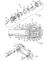
- Fig. 1 shows the elements of the phase-matching coaxial test connector which is to be fitted onto the stripped end of a semirigid coaxial cable.
- Test connector 10 includes a front shell 14, a rear shell 16, a dielectric insert 18, a center contact 20, a coupling 22, and a locking ring 24.
- Front shell 14 has a bore 26 extending therethrough including a front section 28, a center section 30, and a rear section 32. Threads 34 are disposed along rear section 32. Front section 28 of bore 26 has an annular projection 36 with the leading surface thereof being beveled.
- Dielectric insert 18 has a bore 38 extending therethrough in which center contact 20 is secured into position therein by means of annular barb 40. With center contact 20 secured in bore 38 of dielectric insert 18, this assembly is secured in front section 28 of bore 26 with annular projection 36 securing dielectric insert 18 in position therein.
- An annular section 42 of dielectric insert 18 is positioned within center section 30 of bore 26 and includes an opening 44 in axial alignment with bore 46 which is adapted to receive center conductor 50 of semirigid coaxial cable 12 with spring contact members 48 making the electrical connection therewith.
- a pin contact 49 of center contact 20 extends outwardly from insert 18.
- Rear shell 16 has bore 52 to receive outer conductor 54 of coaxial cable 72 and a section 56 is threadably matable with threads 34 of front shell 14 to secure rear shell 16 in position in front shell 14.
- Spring, contact members 58 of arcuate configuration have arcuate-shaped projections 60 against which the end of outer conductor 54 abuts when coaxial cable 12 is positioned within bore 52 as illustrated in Fig.. 2.
- Spring contact members 58 springably engage outer conductor 54 and spring contact members 48 springably engage conductor 50.
- Rear shell 16 has a knurled surface 62 for engagement byan operatorto enable rear shell 16 to be threadably moved along threads 34 of front shell 14 until arcuate projections 60 butt against the inner end of rear section of bore 26 of front shell 14. This structure provides the same electrical length that the coaxial connector has that is to be permanently terminated onto coaxial cable 12.
- Locking ring 24 has a C-shape configuration that mates with annular recess 66 in the exterior surface of front shell 14 and annular recess 68 on the internal surface of coupling member 22 to maintain coupling member 22 in position on front shell 14 for freely rotatable movement relative thereto.
- Coupling member 22 also includes internal threads 74 for securing test connector 10 onto a precision adaptor 72 as part of an automatic network analyzer shown in Fig. 9.
- Automatic network analyzer 74 is manufactured by Hewlett-Packard Corporation and is used for phase angle measurement of the cable to be terminated so that the accuracy of the electrical length of the cable to be terminated is precise prior to permanently terminating another coaxial connector onto the other end of the cable.
- automatic network analyzer 74 To measure the phase angle of the length of cable to be terminated, automatic network analyzer 74 includes an output port and an input port.
- the output port has connected thereto a 7 mm precision connector 76 to which is connected precision adaptor 72, also having a 7 mm precision connector 76.
- the input port also has connected thereto a 7 mm precision connector 78.
- a coaxial cable jumper 80 having coaxial connectors 82 and 84 terminating the ends thereof is connected to input connector 78 and precision adaptor 86 of identical construction as that of precision adaptor 72.
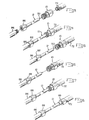
- a length of semirigid coaxial cable 12 is cut to the length that is required. Cable 12 can be straight or curved as required. If cable 12 has not been cut to the correct length, it must have a longer length so that it can be trimmed to the correct length if necessary.
- test connector 10 is positioned onto the other end of cable 12 with center conductor 50 electrically connected with spring contact members 48 of center contact 20 and outer conductor 54 electrically connected with spring contact members 58 representing the outer contact of connector 10 shown in Fig. 2.
- the electrical length of test connector 10 is identical to the electrical length of coaxial connector 88.
- Test connector 10 is connected to precision adaptor 72 while connector 88 is connected to precision adaptor 86. As shown in Fig. 3, 4 and 9, terminated cable 12 is now connected to automatic network analyzer 74 so that the test signal from the output port is transmitted through the ca- bleto be tested and received at the input port of the automatic network analyzer to determine the electrical length of cable 12.
- the electrical lengths of coaxial cables can be correctly determined prior to permanently terminating the coaxial cables so that coaxial cables of accurate electrical lengths can be used in electronic equipment requiring the use of coaxial cables with precise electrical lengths.
Landscapes
- Physics & Mathematics (AREA)
- General Physics & Mathematics (AREA)
- Coupling Device And Connection With Printed Circuit (AREA)
- Manufacturing Of Electrical Connectors (AREA)
Description
- This invention relates to a method for terminating semirigid coaxial cable and more particularly to a method for terminating semirigid coaxial cable that is phase-matched.
- In many high frequency applications such as for example phased array radar, RF performance is extremely important. Many coaxial cable lines are used in the high frequency equipment for such applications. It is highly important that the electrical lengths of these coaxial cable lines be precise so that phase shift of the signal is held to a tight tolerance.
- The usual procedure in the priorart for preparing the coaxial cable lines for high frequency applications is to secure coaxial connectors as by soldering onto the ends of the coaxial cable lines, then test them for electrical length. In most cases, the coaxial cable lines would have to be trimmed to obtain the desired electrical length. To do this, one of the coaxial connectors would have to be removed from. the coaxial cable line, the end of the cable trimmed, and the connector resecured in place. Hopefully, proper trimming of the cable end was done, otherwise, the operation had to be repeated. If too much cable was trimmed, the cable was discarded. Such practice is time-consuming and can result in discarded cable.
- A method is here disclosed for terminating semirigid coaxial cable that is phase-matched which is accomplished by cutting a length of coaxial cable to the exact or approximate desired electrical length. A coaxial connector is permanently terminated onto one end of the cable and a phase-matching test connector is positioned onto the other end of the cable. The cable is tested to determine if the electrical length of the cable is correct. If it is, the test connector is removed and: another coaxial connector is permanently terminated onto the other end of the cable. If the electrical length of the cable is too. long, the test connector is removed, the cable is trimmed to the correct length, the test connector is reapplied onto the cable, the cable is retested, and if now correct, the other coaxial connector is permanently terminated onto the cable.
- Fig. 1 is a perspective-exploded view of the elements of a phase-matching coaxial test connector.
- Fig. 2 is a cross-sectional view of the connector of Fig. 1 applied onto an end of a semirigid coaxial cable.
- Fig. 3-8. illustrate the various steps to permanently terminate an end of a length of cable, position a test connector on the other end of the cable, test the cable, trim the cable, retest the cable, and permanently terminate the cable.
- Fig. 9 shows how the cable is tested.
- Fig. 1 shows the elements of the phase-matching coaxial test connector which is to be fitted onto the stripped end of a semirigid coaxial cable.
Test connector 10 includes afront shell 14, arear shell 16, adielectric insert 18, acenter contact 20, acoupling 22, and alocking ring 24. -
Front shell 14 has abore 26 extending therethrough including afront section 28, acenter section 30, and arear section 32.Threads 34 are disposed alongrear section 32.Front section 28 ofbore 26 has anannular projection 36 with the leading surface thereof being beveled. -
Dielectric insert 18 has abore 38 extending therethrough in whichcenter contact 20 is secured into position therein by means ofannular barb 40. Withcenter contact 20 secured inbore 38 ofdielectric insert 18, this assembly is secured infront section 28 ofbore 26 withannular projection 36 securingdielectric insert 18 in position therein. Anannular section 42 ofdielectric insert 18 is positioned withincenter section 30 ofbore 26 and includes an opening 44 in axial alignment withbore 46 which is adapted to receivecenter conductor 50 of semirigidcoaxial cable 12 withspring contact members 48 making the electrical connection therewith. Apin contact 49 ofcenter contact 20 extends outwardly frominsert 18. -
Rear shell 16 has bore 52 to receiveouter conductor 54 ofcoaxial cable 72 and asection 56 is threadably matable withthreads 34 offront shell 14 to securerear shell 16 in position infront shell 14. Spring, contactmembers 58 of arcuate configuration have arcuate-shaped projections 60 against which the end ofouter conductor 54 abuts whencoaxial cable 12 is positioned withinbore 52 as illustrated in Fig.. 2.Spring contact members 58 springably engageouter conductor 54 andspring contact members 48 springably engageconductor 50.Rear shell 16 has aknurled surface 62 for engagement byan operatorto enablerear shell 16 to be threadably moved alongthreads 34 offront shell 14 untilarcuate projections 60 butt against the inner end of rear section ofbore 26 offront shell 14. This structure provides the same electrical length that the coaxial connector has that is to be permanently terminated ontocoaxial cable 12. -
Locking ring 24 has a C-shape configuration that mates withannular recess 66 in the exterior surface offront shell 14 andannular recess 68 on the internal surface ofcoupling member 22 to maintaincoupling member 22 in position onfront shell 14 for freely rotatable movement relative thereto.Coupling member 22 also includesinternal threads 74 for securingtest connector 10 onto aprecision adaptor 72 as part of an automatic network analyzer shown in Fig. 9.Automatic network analyzer 74 is manufactured by Hewlett-Packard Corporation and is used for phase angle measurement of the cable to be terminated so that the accuracy of the electrical length of the cable to be terminated is precise prior to permanently terminating another coaxial connector onto the other end of the cable. - To measure the phase angle of the length of cable to be terminated,
automatic network analyzer 74 includes an output port and an input port. The output port has connected thereto a 7mm precision connector 76 to which is connectedprecision adaptor 72, also having a 7mm precision connector 76. The input port also has connected thereto a 7 mm precision connector 78. Acoaxial cable jumper 80 havingcoaxial connectors precision adaptor 86 of identical construction as that ofprecision adaptor 72. - To measure the phase angle of a length of semirigid
coaxial cable 12 to be tested and then to be permanently terminated, the following procedure is utilized. A length of semirigidcoaxial cable 12 is cut to the length that is required.Cable 12 can be straight or curved as required. Ifcable 12 has not been cut to the correct length, it must have a longer length so that it can be trimmed to the correct length if necessary. - After
cable 12 has been cut to the desired length and the ends prepared for termination,coaxial connector 88 is permanently terminated on one end ofcable 12 and thentest connector 10 is positioned onto the other end ofcable 12 withcenter conductor 50 electrically connected withspring contact members 48 ofcenter contact 20 andouter conductor 54 electrically connected withspring contact members 58 representing the outer contact ofconnector 10 shown in Fig. 2. The electrical length oftest connector 10 is identical to the electrical length ofcoaxial connector 88. -
Test connector 10 is connected toprecision adaptor 72 whileconnector 88 is connected toprecision adaptor 86. As shown in Fig. 3, 4 and 9, terminatedcable 12 is now connected toautomatic network analyzer 74 so that the test signal from the output port is transmitted through the ca- bleto be tested and received at the input port of the automatic network analyzer to determine the electrical length ofcable 12. - If the electrical length of
cable 12 is correct, then anothercoaxial connector 88 identical tocoaxial connector 88 is permanently terminated onto the other end ofcable 12. The terminated cable can once again be tested to make certain that the cable length is correct. The cable is ready for use. Ifcable 12 is slightly too long,cable 12 is removed fromtest connector 10, the end of the cable is trimmed to the correct electrical length by means of a trimming tool whereaftercable 12 is reconnected to testconnector 10 and the electrical length of the trimmed cable is once again determined byautomatic network analyzer 74. If the electrical length ofcable 12 is now correct,cable 12 is removed fromtest connector 10 andcoaxial connector 88 is permanently terminated onto trimmedcable 12 whereafter the electrical length of permanentlyter- minatedcable 12 is measured to make certain that the electrical length is as it should be. - In accordance with the present invention, the electrical lengths of coaxial cables can be correctly determined prior to permanently terminating the coaxial cables so that coaxial cables of accurate electrical lengths can be used in electronic equipment requiring the use of coaxial cables with precise electrical lengths.
- While the present invention has been described in conjunction with the use of semirigid coaxial cable, it is to be understood that the present invention can be used in conjunction with other types of coaxial cable which are to be used in equipment in which electrical length of the coaxial cables is an important factor.
Claims (2)
Applications Claiming Priority (2)
| Application Number | Priority Date | Filing Date | Title |
|---|---|---|---|
| US06/408,958 US4441781A (en) | 1982-08-17 | 1982-08-17 | Phase-matched semirigid coaxial cable and method for terminating the same |
| US408958 | 1982-08-17 |
Publications (2)
| Publication Number | Publication Date |
|---|---|
| EP0102166A1 EP0102166A1 (en) | 1984-03-07 |
| EP0102166B1 true EP0102166B1 (en) | 1986-03-12 |
Family
ID=23618459
Family Applications (1)
| Application Number | Title | Priority Date | Filing Date |
|---|---|---|---|
| EP83304114A Expired EP0102166B1 (en) | 1982-08-17 | 1983-07-15 | Method for terminating phase-matched semirigid coaxial cable |
Country Status (6)
| Country | Link |
|---|---|
| US (1) | US4441781A (en) |
| EP (1) | EP0102166B1 (en) |
| JP (1) | JPS5951412A (en) |
| CA (1) | CA1209658A (en) |
| DE (1) | DE3362539D1 (en) |
| IL (1) | IL69350A (en) |
Families Citing this family (28)
| Publication number | Priority date | Publication date | Assignee | Title |
|---|---|---|---|---|
| US4557546A (en) * | 1983-08-18 | 1985-12-10 | Sealectro Corporation | Solderless coaxial connector |
| US4688877A (en) * | 1983-08-18 | 1987-08-25 | Sealectro Corporation | Solderless coaxial connector |
| US4641428A (en) * | 1985-10-04 | 1987-02-10 | Burndy Corporation | Automatic method of making terminated coaxial leads |
| JPS6391982A (en) * | 1986-10-03 | 1988-04-22 | 株式会社 潤工社 | Phase adjusting coaxial connector |
| US5021001A (en) * | 1987-01-29 | 1991-06-04 | Lucas Weinschel Inc. | Multiple use electrical connector having planar exposed surface |
| US4836801A (en) * | 1987-01-29 | 1989-06-06 | Lucas Weinschel, Inc. | Multiple use electrical connector having planar exposed surface |
| US4815986A (en) * | 1987-08-14 | 1989-03-28 | Lucas Weinschel, Inc. | Self-aligning blind mate connector |
| US4854893A (en) * | 1987-11-30 | 1989-08-08 | Pyramid Industries, Inc. | Coaxial cable connector and method of terminating a cable using same |
| US4923412A (en) * | 1987-11-30 | 1990-05-08 | Pyramid Industries, Inc. | Terminal end for coaxial cable |
| NL8801841A (en) * | 1988-07-21 | 1990-02-16 | White Products Bv | DEMONTABLE COAXIAL COUPLING. |
| US4936800A (en) * | 1989-08-30 | 1990-06-26 | Amp Incorporated | Precision test connector |
| US4995837A (en) * | 1989-08-30 | 1991-02-26 | Amp Incorporated | Precision test connector |
| USD341126S (en) | 1990-03-08 | 1993-11-09 | W. L. Gore & Associates, Inc. | Beaded coaxial electric cable connector |
| US5154635A (en) * | 1990-08-31 | 1992-10-13 | Kaufman Harold R | Coaxial vacuum cable |
| US5352134A (en) * | 1993-06-21 | 1994-10-04 | Cabel-Con, Inc. | RF shielded coaxial cable connector |
| JP2598574Y2 (en) * | 1993-08-25 | 1999-08-16 | 矢崎総業株式会社 | Connector shielded wire connection structure |
| DE4418259C1 (en) * | 1994-05-25 | 1995-08-24 | Hirschmann Richard Gmbh Co | Multipole electrical connector for stranded cables |
| EP0875081B1 (en) * | 1996-10-23 | 2005-12-28 | Thomas & Betts International, Inc. | Coaxial cable connector |
| US6273736B1 (en) * | 1997-07-22 | 2001-08-14 | Applied Materials, Inc. | Safety guard for an RF connector |
| EP1180823B1 (en) * | 2000-08-09 | 2004-06-02 | Phoenix Contact GmbH & Co. KG | Cable-connection or cable-joint device |
| US6428356B1 (en) | 2001-08-13 | 2002-08-06 | Belden Wire & Cable Company | Test interface for coaxial cable |
| EP1467450A1 (en) * | 2003-04-09 | 2004-10-13 | Hirschmann Electronics GmbH & Co. KG | Connector for coaxial connection |
| US7442084B2 (en) * | 2006-06-21 | 2008-10-28 | John Mezzalingua Associates, Inc. | Filter housing |
| US9099791B2 (en) * | 2013-06-21 | 2015-08-04 | Tektronix, Inc. | Cable assembly having a coaxial cable with outer conductor not protruding a housing surrounding the cable |
| TWM470363U (en) * | 2013-07-03 | 2014-01-11 | Infinet Technology Ltd | Adjustable matched cable assemblies and signal transmission system thereof |
| US9601444B2 (en) | 2014-02-27 | 2017-03-21 | Tektronix, Inc. | Cable mounted modularized signal conditioning apparatus system |
| DE102016107194A1 (en) * | 2016-04-19 | 2017-10-19 | OET GmbH | Separator device for separating a fluid, in particular a lubricant from a coolant fluid |
| RU2649678C1 (en) * | 2017-03-30 | 2018-04-04 | Акционерное общество "Научно-производственная фирма "Микран" | Ultra-wide band coaxial phase shifter |
Family Cites Families (14)
| Publication number | Priority date | Publication date | Assignee | Title |
|---|---|---|---|---|
| US2302143A (en) * | 1939-09-19 | 1942-11-17 | Internat Telephone & Radio Mfg | High frequency voltmeter |
| US2677807A (en) * | 1948-12-11 | 1954-05-04 | Hewlett Packard Co | Coupling system for sampling fields on transmission lines |
| US3282805A (en) * | 1963-06-04 | 1966-11-01 | Western Electric Co | Method of detecting discontinuities in cable conductors |
| US3201721A (en) * | 1963-12-30 | 1965-08-17 | Western Electric Co | Coaxial line to strip line connector |
| US3287672A (en) * | 1964-11-19 | 1966-11-22 | Marvin L Heinz | Disc-loaded waveguide tuning machine which automatically tunes successive cavities by indenting waveguide wall |
| US3452429A (en) * | 1966-09-08 | 1969-07-01 | Electronics Inc Of Pennsylvani | Compensation of coaxial cables |
| US3525057A (en) * | 1967-03-30 | 1970-08-18 | Univ Iowa State Res Found Inc | Impedance-matching device |
| US3539976A (en) * | 1968-01-04 | 1970-11-10 | Amp Inc | Coaxial connector with controlled characteristic impedance |
| US3663901A (en) * | 1970-02-27 | 1972-05-16 | Amp Inc | Tuned coaxial device |
| BE794948A (en) * | 1972-02-02 | 1973-08-02 | Raychem Corp | CONNECTION DEVICE FOR COAXIAL CABLES |
| US3757272A (en) * | 1972-07-12 | 1973-09-04 | Raytheon Co | Strip transmission line coupler |
| US3825861A (en) * | 1973-09-10 | 1974-07-23 | Eg & G Inc | Coaxial line to strip line connector |
| GB1490421A (en) * | 1975-01-21 | 1977-11-02 | Standard Telephones Cables Ltd | Cable connector |
| US4115749A (en) * | 1977-04-25 | 1978-09-19 | The United States Of America As Represented By The Secretary Of The Air Force | Microwave hybrid phase matching spacer |
-
1982
- 1982-08-17 US US06/408,958 patent/US4441781A/en not_active Expired - Lifetime
-
1983
- 1983-07-15 EP EP83304114A patent/EP0102166B1/en not_active Expired
- 1983-07-15 DE DE8383304114T patent/DE3362539D1/en not_active Expired
- 1983-07-26 IL IL69350A patent/IL69350A/en not_active IP Right Cessation
- 1983-07-27 CA CA000433372A patent/CA1209658A/en not_active Expired
- 1983-08-12 JP JP58147917A patent/JPS5951412A/en active Pending
Also Published As
| Publication number | Publication date |
|---|---|
| IL69350A (en) | 1988-07-31 |
| JPS5951412A (en) | 1984-03-24 |
| CA1209658A (en) | 1986-08-12 |
| IL69350A0 (en) | 1983-11-30 |
| EP0102166A1 (en) | 1984-03-07 |
| US4441781A (en) | 1984-04-10 |
| DE3362539D1 (en) | 1986-04-17 |
Similar Documents
| Publication | Publication Date | Title |
|---|---|---|
| EP0102166B1 (en) | Method for terminating phase-matched semirigid coaxial cable | |
| US4967173A (en) | Short airline calibration standards and methods for error-corrected microwave network analysis | |
| US4691976A (en) | Coaxial cable tap connector | |
| CA1249350A (en) | High frequency connector | |
| US4738009A (en) | Coaxial cable tap | |
| US4979911A (en) | Cable collet termination | |
| EP1395839B1 (en) | Apparatus with interchangeable modules for measuring characteristics of cables and networks | |
| US7108527B2 (en) | Sex changeable adapter for coaxial connectors | |
| US4672342A (en) | Method and means of construction of a coaxial cable and connector-transformer assembly for connecting coaxial cables of different impedance | |
| US4559704A (en) | Tool and method for trimming coaxial cable | |
| JPH03105257A (en) | Connector assembly for test | |
| US4891015A (en) | Universal connector with interchangeable male and female sleeves for use in network analyzers and microwave devices | |
| EP0476353A1 (en) | Slotless female contact | |
| US4845423A (en) | Electrically short air line for network analyzer calibration | |
| US4291936A (en) | Coaxial connector with improved female conductor structure | |
| US4666230A (en) | Coaxial cable connector assembly | |
| US20040018783A1 (en) | Automated connection of connectors to cables | |
| US6428356B1 (en) | Test interface for coaxial cable | |
| CN219321683U (en) | Adjustable armored cable assembly | |
| US4936800A (en) | Precision test connector | |
| WO2021173221A1 (en) | Test probe adapter | |
| US11624764B1 (en) | Flange mount coaxial connector system | |
| US20240072460A1 (en) | Cable connector having pin trim markings structurally configured to indicate predetermined cut locations so as to provide consistent radio frequency performance | |
| JP4297800B2 (en) | Jig used for connector characteristic measurement, and connector characteristic measurement method | |
| US8800135B2 (en) | Stinger cutting guide |
Legal Events
| Date | Code | Title | Description |
|---|---|---|---|
| PUAI | Public reference made under article 153(3) epc to a published international application that has entered the european phase |
Free format text: ORIGINAL CODE: 0009012 |
|
| AK | Designated contracting states |
Designated state(s): BE DE FR GB IT NL SE |
|
| 17P | Request for examination filed |
Effective date: 19840809 |
|
| ITF | It: translation for a ep patent filed | ||
| GRAA | (expected) grant |
Free format text: ORIGINAL CODE: 0009210 |
|
| AK | Designated contracting states |
Kind code of ref document: B1 Designated state(s): BE DE FR GB IT NL SE |
|
| REF | Corresponds to: |
Ref document number: 3362539 Country of ref document: DE Date of ref document: 19860417 |
|
| ET | Fr: translation filed | ||
| PLBE | No opposition filed within time limit |
Free format text: ORIGINAL CODE: 0009261 |
|
| STAA | Information on the status of an ep patent application or granted ep patent |
Free format text: STATUS: NO OPPOSITION FILED WITHIN TIME LIMIT |
|
| 26N | No opposition filed | ||
| ITTA | It: last paid annual fee | ||
| REG | Reference to a national code |
Ref country code: GB Ref legal event code: 732E |
|
| EAL | Se: european patent in force in sweden |
Ref document number: 83304114.8 |
|
| PGFP | Annual fee paid to national office [announced via postgrant information from national office to epo] |
Ref country code: GB Payment date: 19960617 Year of fee payment: 14 |
|
| PGFP | Annual fee paid to national office [announced via postgrant information from national office to epo] |
Ref country code: SE Payment date: 19960624 Year of fee payment: 14 Ref country code: NL Payment date: 19960624 Year of fee payment: 14 |
|
| PGFP | Annual fee paid to national office [announced via postgrant information from national office to epo] |
Ref country code: FR Payment date: 19960715 Year of fee payment: 14 |
|
| PGFP | Annual fee paid to national office [announced via postgrant information from national office to epo] |
Ref country code: DE Payment date: 19960730 Year of fee payment: 14 |
|
| PGFP | Annual fee paid to national office [announced via postgrant information from national office to epo] |
Ref country code: BE Payment date: 19960806 Year of fee payment: 14 |
|
| PG25 | Lapsed in a contracting state [announced via postgrant information from national office to epo] |
Ref country code: GB Free format text: LAPSE BECAUSE OF NON-PAYMENT OF DUE FEES Effective date: 19970715 |
|
| PG25 | Lapsed in a contracting state [announced via postgrant information from national office to epo] |
Ref country code: SE Effective date: 19970716 |
|
| PG25 | Lapsed in a contracting state [announced via postgrant information from national office to epo] |
Ref country code: BE Free format text: LAPSE BECAUSE OF NON-PAYMENT OF DUE FEES Effective date: 19970731 |
|
| BERE | Be: lapsed |
Owner name: AMP INC. (UNE SOC. DE PENNSYLVANIE) Effective date: 19970731 |
|
| PG25 | Lapsed in a contracting state [announced via postgrant information from national office to epo] |
Ref country code: NL Free format text: LAPSE BECAUSE OF NON-PAYMENT OF DUE FEES Effective date: 19980201 |
|
| GBPC | Gb: european patent ceased through non-payment of renewal fee |
Effective date: 19970715 |
|
| PG25 | Lapsed in a contracting state [announced via postgrant information from national office to epo] |
Ref country code: FR Free format text: LAPSE BECAUSE OF NON-PAYMENT OF DUE FEES Effective date: 19980331 |
|
| NLV4 | Nl: lapsed or anulled due to non-payment of the annual fee |
Effective date: 19980201 |
|
| PG25 | Lapsed in a contracting state [announced via postgrant information from national office to epo] |
Ref country code: DE Free format text: LAPSE BECAUSE OF NON-PAYMENT OF DUE FEES Effective date: 19980401 |
|
| EUG | Se: european patent has lapsed |
Ref document number: 83304114.8 |
|
| REG | Reference to a national code |
Ref country code: FR Ref legal event code: ST |