EP0102072B2 - Method and apparatus for the production of carbon blacks - Google Patents
Method and apparatus for the production of carbon blacks Download PDFInfo
- Publication number
- EP0102072B2 EP0102072B2 EP83108439A EP83108439A EP0102072B2 EP 0102072 B2 EP0102072 B2 EP 0102072B2 EP 83108439 A EP83108439 A EP 83108439A EP 83108439 A EP83108439 A EP 83108439A EP 0102072 B2 EP0102072 B2 EP 0102072B2
- Authority
- EP
- European Patent Office
- Prior art keywords
- zone
- carbon black
- feedstock
- reactor
- generally
- Prior art date
- Legal status (The legal status is an assumption and is not a legal conclusion. Google has not performed a legal analysis and makes no representation as to the accuracy of the status listed.)
- Expired - Lifetime
Links
- 239000006229 carbon black Substances 0.000 title claims abstract description 82
- 238000000034 method Methods 0.000 title claims abstract description 18
- 235000019241 carbon black Nutrition 0.000 title abstract description 72
- 238000004519 manufacturing process Methods 0.000 title abstract description 17
- 238000011144 upstream manufacturing Methods 0.000 claims abstract description 32
- 239000000567 combustion gas Substances 0.000 claims abstract description 29
- 238000000197 pyrolysis Methods 0.000 claims abstract description 25
- 239000007921 spray Substances 0.000 claims abstract description 17
- 238000002485 combustion reaction Methods 0.000 claims abstract description 16
- 239000012530 fluid Substances 0.000 claims description 19
- 238000006243 chemical reaction Methods 0.000 claims description 16
- 238000002347 injection Methods 0.000 claims description 12
- 239000007924 injection Substances 0.000 claims description 12
- 238000002156 mixing Methods 0.000 claims description 11
- 239000007800 oxidant agent Substances 0.000 claims description 8
- 230000001590 oxidative effect Effects 0.000 claims description 8
- 239000003595 mist Substances 0.000 claims description 2
- 238000009826 distribution Methods 0.000 abstract description 14
- 239000000446 fuel Substances 0.000 abstract description 10
- 239000007789 gas Substances 0.000 abstract description 6
- LZZYPRNAOMGNLH-UHFFFAOYSA-M Cetrimonium bromide Chemical compound [Br-].CCCCCCCCCCCCCCCC[N+](C)(C)C LZZYPRNAOMGNLH-UHFFFAOYSA-M 0.000 description 12
- VNWKTOKETHGBQD-UHFFFAOYSA-N methane Chemical compound C VNWKTOKETHGBQD-UHFFFAOYSA-N 0.000 description 9
- 230000001427 coherent effect Effects 0.000 description 8
- 239000007788 liquid Substances 0.000 description 6
- 241000196324 Embryophyta Species 0.000 description 5
- 238000010791 quenching Methods 0.000 description 5
- 230000007423 decrease Effects 0.000 description 4
- 239000002245 particle Substances 0.000 description 4
- 239000000523 sample Substances 0.000 description 4
- 229910052799 carbon Inorganic materials 0.000 description 3
- 238000000354 decomposition reaction Methods 0.000 description 3
- 230000003287 optical effect Effects 0.000 description 3
- OKTJSMMVPCPJKN-UHFFFAOYSA-N Carbon Chemical compound [C] OKTJSMMVPCPJKN-UHFFFAOYSA-N 0.000 description 2
- MYMOFIZGZYHOMD-UHFFFAOYSA-N Dioxygen Chemical compound O=O MYMOFIZGZYHOMD-UHFFFAOYSA-N 0.000 description 2
- ATUOYWHBWRKTHZ-UHFFFAOYSA-N Propane Chemical compound CCC ATUOYWHBWRKTHZ-UHFFFAOYSA-N 0.000 description 2
- 238000002835 absorbance Methods 0.000 description 2
- QVGXLLKOCUKJST-UHFFFAOYSA-N atomic oxygen Chemical compound [O] QVGXLLKOCUKJST-UHFFFAOYSA-N 0.000 description 2
- 239000006185 dispersion Substances 0.000 description 2
- 229910052739 hydrogen Inorganic materials 0.000 description 2
- 239000000463 material Substances 0.000 description 2
- 229910052751 metal Inorganic materials 0.000 description 2
- 239000002184 metal Substances 0.000 description 2
- 239000003345 natural gas Substances 0.000 description 2
- 239000001301 oxygen Substances 0.000 description 2
- 229910052760 oxygen Inorganic materials 0.000 description 2
- 230000035515 penetration Effects 0.000 description 2
- 239000011541 reaction mixture Substances 0.000 description 2
- 239000011819 refractory material Substances 0.000 description 2
- 239000002002 slurry Substances 0.000 description 2
- APSBXTVYXVQYAB-UHFFFAOYSA-M sodium docusate Chemical compound [Na+].CCCCC(CC)COC(=O)CC(S([O-])(=O)=O)C(=O)OCC(CC)CCCC APSBXTVYXVQYAB-UHFFFAOYSA-M 0.000 description 2
- 239000007787 solid Substances 0.000 description 2
- 238000005507 spraying Methods 0.000 description 2
- XLYOFNOQVPJJNP-UHFFFAOYSA-N water Substances O XLYOFNOQVPJJNP-UHFFFAOYSA-N 0.000 description 2
- 239000004215 Carbon black (E152) Substances 0.000 description 1
- UGFAIRIUMAVXCW-UHFFFAOYSA-N Carbon monoxide Chemical compound [O+]#[C-] UGFAIRIUMAVXCW-UHFFFAOYSA-N 0.000 description 1
- 241000005139 Lycium andersonii Species 0.000 description 1
- 239000004594 Masterbatch (MB) Substances 0.000 description 1
- 229910000831 Steel Inorganic materials 0.000 description 1
- 238000005299 abrasion Methods 0.000 description 1
- 230000001133 acceleration Effects 0.000 description 1
- 238000013019 agitation Methods 0.000 description 1
- HSFWRNGVRCDJHI-UHFFFAOYSA-N alpha-acetylene Natural products C#C HSFWRNGVRCDJHI-UHFFFAOYSA-N 0.000 description 1
- PNEYBMLMFCGWSK-UHFFFAOYSA-N aluminium oxide Inorganic materials [O-2].[O-2].[O-2].[Al+3].[Al+3] PNEYBMLMFCGWSK-UHFFFAOYSA-N 0.000 description 1
- 239000003945 anionic surfactant Substances 0.000 description 1
- 239000012736 aqueous medium Substances 0.000 description 1
- 239000007864 aqueous solution Substances 0.000 description 1
- 230000008033 biological extinction Effects 0.000 description 1
- 229910002091 carbon monoxide Inorganic materials 0.000 description 1
- 239000003575 carbonaceous material Substances 0.000 description 1
- 238000004939 coking Methods 0.000 description 1
- 238000004590 computer program Methods 0.000 description 1
- 238000010276 construction Methods 0.000 description 1
- 239000002826 coolant Substances 0.000 description 1
- 238000001816 cooling Methods 0.000 description 1
- 239000012809 cooling fluid Substances 0.000 description 1
- 230000003247 decreasing effect Effects 0.000 description 1
- 230000001419 dependent effect Effects 0.000 description 1
- 235000019329 dioctyl sodium sulphosuccinate Nutrition 0.000 description 1
- 229910001882 dioxygen Inorganic materials 0.000 description 1
- YHAIUSTWZPMYGG-UHFFFAOYSA-L disodium;2,2-dioctyl-3-sulfobutanedioate Chemical compound [Na+].[Na+].CCCCCCCCC(C([O-])=O)(C(C([O-])=O)S(O)(=O)=O)CCCCCCCC YHAIUSTWZPMYGG-UHFFFAOYSA-L 0.000 description 1
- 238000010494 dissociation reaction Methods 0.000 description 1
- 230000005593 dissociations Effects 0.000 description 1
- 238000005315 distribution function Methods 0.000 description 1
- 230000000694 effects Effects 0.000 description 1
- 125000002534 ethynyl group Chemical group [H]C#C* 0.000 description 1
- 229930195733 hydrocarbon Natural products 0.000 description 1
- 150000002430 hydrocarbons Chemical class 0.000 description 1
- 239000001257 hydrogen Substances 0.000 description 1
- 150000002431 hydrogen Chemical class 0.000 description 1
- 238000005259 measurement Methods 0.000 description 1
- 238000010907 mechanical stirring Methods 0.000 description 1
- 239000002609 medium Substances 0.000 description 1
- 239000000203 mixture Substances 0.000 description 1
- 239000001294 propane Substances 0.000 description 1
- 230000003014 reinforcing effect Effects 0.000 description 1
- 238000005096 rolling process Methods 0.000 description 1
- 239000000243 solution Substances 0.000 description 1
- 238000001228 spectrum Methods 0.000 description 1
- 239000010959 steel Substances 0.000 description 1
- 239000000725 suspension Substances 0.000 description 1
- 230000002195 synergetic effect Effects 0.000 description 1
- 238000007039 two-step reaction Methods 0.000 description 1
- 238000004506 ultrasonic cleaning Methods 0.000 description 1
- 238000009827 uniform distribution Methods 0.000 description 1
- 238000005303 weighing Methods 0.000 description 1
Images
Classifications
-
- C—CHEMISTRY; METALLURGY
- C09—DYES; PAINTS; POLISHES; NATURAL RESINS; ADHESIVES; COMPOSITIONS NOT OTHERWISE PROVIDED FOR; APPLICATIONS OF MATERIALS NOT OTHERWISE PROVIDED FOR
- C09C—TREATMENT OF INORGANIC MATERIALS, OTHER THAN FIBROUS FILLERS, TO ENHANCE THEIR PIGMENTING OR FILLING PROPERTIES ; PREPARATION OF CARBON BLACK ; PREPARATION OF INORGANIC MATERIALS WHICH ARE NO SINGLE CHEMICAL COMPOUNDS AND WHICH ARE MAINLY USED AS PIGMENTS OR FILLERS
- C09C1/00—Treatment of specific inorganic materials other than fibrous fillers; Preparation of carbon black
- C09C1/44—Carbon
- C09C1/48—Carbon black
- C09C1/50—Furnace black ; Preparation thereof
Definitions
- the invention relates to new carbon black reactors. In another aspect, the invention relates to new methods for producing carbon black.
- US-A- 3 922 335 describes a process for producing carbon black and an apparatus suitable for use in this process.
- High speed combustion gases (at least Mach 0.35) are passed through an annular feedstock injection zone.
- the annular feedstock injection zone can be varied (col. 17, 1. 33 ff.) to square or rectangular cross-section and the feedstock can be injected from an axial feed nozzle radially outwardly and from the wall around the annular feedstock injection zone radially inwardly.
- the reference provides that the combustion gases can be conducted from their producing chamber through constricted annular feedstock injection zone.
- US-A-4 077 761 describes a carbon black reactor with axial flow burner.
- a flow disrupting bluff body is provided in the flow stream of the oxidant upstream of the point of fuel injection.
- the present invention allows the production of a carbon black characterized by a CTAB surface area of between about 50 and 500 m 2 /g and an aggregate size distribution breadth index G of 1.85 or greater.
- This type of carbon black imparts low hysteresis properties to rubber into which it has been compounded and can therefore be very desirable for the production of belts and tires, for example.
- the present invention allows the production of a carbon black characterized by a CTAB surface area of between about 50 and 500 m 2 /g and an aggregate size distribution breadth index G of 1.20 or less.
- This type of carbon black has a high positive tint residual value which imparts high abrasion resistance in tires.
- the reactor of this invention is well-adapted for producing carbon black at high yields and low grit levels.
- an apparatus 2 comprises, serially arranged, a combustion zone 4, a mixing zone 6, and a pyrolysis zone 8.
- the combustion zone 4 comprises a combustion chamber 10 defined by a generally cylindrical sidewall 12 and a generally annular upstream end wall 14 having a passage 16 therethrough generally axially directed into the generally cylindrical combustion chamber 10.
- the sidewall 12 and endwall 14 are generally formed from a refractory material to resist high temperatures. Oxidant fluid and combustible fluid are introduced into the chamber 10 via the passage 16.
- the passage 16 leads from chamber 18 which is defined by a housing 20.
- the housing 20 can be formed from metal, such as steel, and preferably comprises a generally tubular sidewall 21 so that the chamber 18 is generally cylindrical as it extends from the passage 16, preferably in axial alignment therewith.
- a tubular member 23 extends through the chamber 18 axially and empties into the passage 16.
- the tubular member 23 carries the combustible fluid which is mixed with oxidant fluid from the chamber 18 in the passage 16.
- the housing 20 is closed at its upstream end by a plate 24 affixed to a flange 26 which circumscribes the upstream end of the housing 20.
- the tubular member 23 enters the chamber 18 in an axial direction through the plate 24.
- An annulus 19 defined between the plate 24 and the tubular member 23 provides a passage for the introduction of coolant, such as a cool gas, into the chamber 18 to protect the metal components in the neighborhood of flange 24 from high temperatures.
- a duct 27 opens into the chamber 18 through the sidewall 21. The duct 27 can open into the chamber 18 tangentially if desired, although a duct opening into the chamber 18 generally normally with respect to the longitudinal axis of the chamber 18 has been used with good results.
- the generally annular surface 14 is a part of a ring or choke 28 positioned between the chambers 18 and 10 and defining the passage 16, because the ring helps to distribute oxidant fluid from the chamber 18 into the chamber 10.
- the ring 28 can be formed from a section of tubular refractory.
- the tubular member 23 preferably empties into the passage 16 through a plurality of radially outwardly directed ports or orifices 30 passing through the sidewall of the tubular member 23 where a gaseous combustible fluid is utilized, for ease of fabrication and reliability of operation.
- a bluff body, in the form of a generally annular flange 29 is attached to the tubular member 23 slightly downstream of the ports 30 to aid in maintaining stable combustion.
- the flange 29 is positioned upstream of the surface 14, most preferably about 5 cm (2 inches) into the zone 16, as measured from zone 18.
- the reaction flow passage expands between the passage 16 and the zone 10 from a first diameter to a second diameter such that the ratio between the first diameter and the second diameter is between about 0.3 and about 0.8.
- the ratio of the diameters of the flange 29 and the passage 16 is within the range of from about 0.5 to about 0.75.
- the mixing zone 6 comprises a sidewall 31 formed from refractory defining a chamber 32 in axial alignment with and converging from the combustion chamber 10 to a throat 34 and a means 36 for introducing a carbonaceous feestock through the sidewall 31 and into at least one of the converging chamber 32 and the throat 34.
- the converging chamber 32 converges from an inlet having a diameter about the same as that of the combustion chamber 10 to an outlet having a diameter about the same as that of the throat 34.
- a converging chamber which converges at a half-angle of about 18.5 (18 ° 30') has been used with good results.
- the means 36 comprises one or more sets of ports 38, which open into the chamber 32, more preferably, 2 or more sets of ports 38 with at least one set opening into the converging chamber 32 and at least one sat opening into the throat 34 for the positioning of carbonaceous feedstock injectors 40.
- the ports of a set will be circumferentially spaced about the reaction flow passage at a selected position with respect to the longitudinal axis of the reaction flow passage, with the ports being preferably equiangularly spaced from each other for uniform distribution of feestock from the injectors 40 and into the reaction flow passage.
- each set of ports 38 will be arranged in equiangular spacing, for example, 1800, 1200, 900, or 600, and be radially inwardly directed, although they can be canted upstream or downstream as desired. Ports not in use can be sealed with plugs 41.
- the injectors 40 will be positioned through only one set of the ports 38 so that they empty into the flow passage of the reactor at the same longitudinal position. As injectors are moved upstream, the structure of the black increases.
- the tip of each injector is positioned about flush with the reactor wall, to lessen heat exposure and cut down on coking and plugging.
- the injectors 40 can be provided with nozzles 43 which can be canted to introduce carbonaceous feedstock into the reaction flow passage with an upstream or downstream velocity component as desired.
- the nozzles 43 can be selected to introduce the feedstock as a coherent stream or a spray or any other pattern as desired.
- the nozzles be selected to emit a coherent stream of feedstock, so that the dissociation of the feedstock will take place away from the reactor wall and the penetration of the feedstock will be sufficient to cause good distribution of dissociated carbonaceous material across the reaction flow path.
- nozzles which are designed to emit a spray
- spray nozzles are also advantageous where the nozzles are canted, especially when the nozzles are canted to emit feedstock in a downstream direction.
- Solid-cone type spray nozzles which emit atomized feedstock at an angle of divergence of about 150 have been used with good results.
- Jacket cooling air can surround the oil injectors 40, flowing through the annulus between the oil tube and the wall of the port.
- carbon black having a wide aggregate size distribution can be produced.
- the feedstock injectors will be positioned about 0-10 cm (0-4 inches), for example between 2.5 and 7.5 cm (1 and 3 inches), upstream of the pyrolysis zone.
- Such a carbon black is frequently characterized by a negative tint residual and will impart low hystersis to rubber into which it has been compounded.
- carbon black having a very narrow aggregate size distribution can be produced.
- Such a carbon black is frequently characterized by a high or positive tint residual.
- the feedstock or oil injectors 40 will be positioned between about 10 cm (4 inches) and about 91 cm (36 inches) upstream of the pyrolysis zone. usually between about 15 (6) and about 61 cm (24 inches) upstream.
- carbonaceous feedstock can also be injected into the converging chamber 32 and/or throat 34 via optional axial feedstock injector assembly 42, which can be fitted with an appropriate nozzle to dispense liquid or vaporous, preferably liquid, carbonaceous feedstock.
- tube 42 is not installed, however, in the preferred embodiment of this aspect of the invention, the assembly 42, which preferably comprises a feedstock tube 47 coaxially disposed within a water-jacket tube 45, enters the reactor 2 coaxially within the gas tube 23 and extends adjustably from the end of the tube 23 at least into the converging chamber 32.
- the feedstock tube 47 can be fitted with any one of a variety of feedstock nozzles, for example, single or multiple solid jet nozzles with the jets directed axially, radially outwardly, or at an angle, or a solid or a hollow cone nozzle, etc., as desired.
- the pyrolysis zone 8 preferably is comprised of one or more generally cylindrical sections of refractory material 44.
- the mixing zone 6 is preferably a separate section of refractory, so that it can be easily replaced if desired.
- heavy-duty refractory such as chrome-alumina refractory (minimum 9 wt.% Cr 2 0 3 ) manufactured by Didier-Taylor, Cincinnati, Ohio, is preferably employed for at least the construction of the zone 8.
- reaction flow passage undergoes an abrupt expansion as it enters the pyrolysis zone from the mixing zone.
- the half-angle of expansion is near 900, because this configuration has been used with good results.
- the upstream end of the pyrolysis zone is defined by a generally annularly shaped end wall 46 which extends from the downstream end of the throat 34 to the upstream end of pyrolysis zone sidewall 48.
- the pyrolysis zone preferably has a generally circular cross-section in a plane normal to the axis of the reaction flow passage.
- the desired amount of expansion between the zones will depend on reactor flow conditions and the desired properties of the carbon black to be produced.
- the cross sectional area of the reaction flow passage defined by sidewall 48 in a plane normal to the reactor axis will be in the range of from about 2.8 to about 13 times larger than the cross sectional area of the reaction passage at the throat 34.
- An expansion ratio toward the lower end of this range tends to provide a carbon black product characterized by higher surface area and lower structure, while an expansion ratio toward the upper end of the range provides a carbon black product characterized by lower surface area and higher structure.
- the pyrolysis zone is provided with a plurality of abrupt expansions in the reaction flow passage.
- the upstream end of the pyrolysis zone 8 comprises serially arranged from the upstream end wall 46 a first generally cylindrical zone 50 having a first diameter and a second generally cylindrical zone 52 having a second diameter which is larger than the first diameter.
- the first generally cylindrical zone 50 has a diameter sufficient so that the area ratio between the first generally cylindrical zone 50 and the throat 34 is in the range of from about 2.8:1 to about 13:1.
- the flow area ratio between the second generally cylindrical zone 52 and the first generally cylindrical zone 50 is preferably from about 1:1 to about 4:1.
- the first generally cylindrical zone 50 preferably has a length in the range of from about 0.1 to about 15 times the diameter of the throat 34, usually from about 0.5 to about 10 diameters.
- an annular shoulder 54 separates the zones 50 and 52, because this design provides a good flow pattern.
- the pyrolysis zone 8 is further provided with a means 56 for supplying cooling fluid to the reaction flow passage.
- the means 56 comprises ports 58 opening into the pyrolysis zone 8.
- at least one of the ports 58 carries a tube and spray nozzle assembly 60 for introducing a quench fluid into the zone 8 to stop the pyrolysis reaction.
- the means 56 will be positioned downstream of the outlet of the throat at a distance of from about 5 to about 45 throat diameters, usually at a distance of between about 8 and about 20 throat diameters. In other terms, the means 56 will be positioned between about 0.5 m (1.5 feet) and about 6 m (20 feet) downstream of the throat. Positioning the means 56 close to the throat produces low photolometer product.
- the means 56 is positioned downstream from the throat at a distance to produce a photolometer value of at least about 70 and is preferably designed to spray water. Further downstream of the quench means 56, the reaction mixture is further cooled to facilitate handling, and can be processed in conventional equipment.
- Certain aspects of the invention are carried out according to a process comprising flowing a stream of hot combustion gases having a temperature sufficiently high to decompose a carbonaceous feedstock and form carbon black sequentially through a converging zone, a throat and an abruptly diverging zone: and introducing the carbonaceous feedstock transversely into the stream of hot combustion gases from the periphery of the stream for decomposition to form the carbon black.
- the oxidant fluid comprises air, since it is inexpensive and plentiful, preferably preheated air at a temperature of from about 371 (700) to about 677 ° C (1250°F), since employing preheated air is an inexpensive method of supplying heat to the reactor to drive the pyrolysis reaction and aids in forming a high-structure product.
- preheated air is an inexpensive method of supplying heat to the reactor to drive the pyrolysis reaction and aids in forming a high-structure product.
- pure oxygen or oxygen-enriched air is also suitable, and besides having the advantage of producing a higher structure product, is the preferred oxidant where a low BTU fuel is burned.
- the combustible fluid will comprise mostly methane, because methane is the major component of natural gas and synthetic natural gas and these materials are suitable combustible fluids and are inexpensive.
- Other combustible fluids containing one or more components, for example selected from hydrogen, carbon monoxide, acetylene and propane are also suitable.
- An inexpensive fuel commonly found in a carbon black plant comprises off-gases from the filter bags, especially from soft black manufacture. This fuel is a low-BTU fuel, containing about 100 BTU/SCF, and generally 25-30 vol% or so of H 2 and CO.
- Liquid fuels such as are used in some conventional carbon black plants can also be used in the present invention.
- the feedstock is used as fuel.
- stoichiometric or excess air is mixed with the combustible fluid and ignited as the mixture is introduced into the combustion zone.
- stoichiometric is meant an amount which results in the essential absence of both molecular oxygen and combustible materials in the combustion gases.
- a greater than stoichiometric amount of air, commonly called “excess” air, will result in the presence of reactive oxygen in the combustion gases.
- Fifty percent excess air is frequently used in carbon black manufacturing processes, and this means that 150% of the stoichiometric amount of air has been mixed with the combustible fluid.
- the "excess" air partly consumes the carbonaceous feedstock and therefore results in lost yield. These are at least two reasons, however, why its presence can be desirable. First, as the excess air reacts with the feedstock, it generates both turbulence and heat, and therefore a finer and more uniform carbon black product. Secondly, the excess air dilutes the combustion gases and reduces their temperature, protecting equipment.
- the reactor is capable of withstanding the temperatures of near stoichiometric combustion of the air and fuel and concommitantly generates sufficient turbulence downstream of the feedstock injection to form the desired particle size of carbon black, and the combustion gas stream contains sufficient heat to pyrolyze the feedstock particles, excess air can be avoided, since it results in reduced yields due to combustion of a portion of the feedstock.
- natural gas is used as the combustible fluid, it is preferably mixed with air at a volume ratio of from about 10:1, which is near stoichiometric, to about 20:1, which would be about 100% excess air.
- the carbonaceous feedstock which is injected into the combustion gas stream from its periphery is generally any of the hydrocarbon feeds suitable for forming carbon black.
- the carbonaceous feedstock will be a liquid, contain about 90 weight percent carbon and have a density greater than that of water.
- the feedstock will be characterized by a Bureau of Mines Correlation Index, BMCI of between about 90 and about 150.
- the carbonaceous feedstock is preferably preheated to a temperature in the range of 120 (250) to about 260 ° C (500 ° F) prior to injection into the combustion gases. It is important that the streams of feedstock do not penetrate sufficiently far to impinge on the wall of the reactor.
- the feedstock be injected at a pressure of at least 3.4 . 10-5 Pa (50 psig).
- the same carbonaceous feedstock can also be introduced into the reactor from a position along the reactor axis. It will be appreciated that injecting the feedstock through a smaller orifice requires a higher pressure to achieve the same penetration.
- the carbonaceous feedstock is introduced into the converging zone from the periphery thereof.
- a carbon black product having a CTAB surface area in the range of between about 50 and about 500 m 2 /g, usually between about 50 and about 200 m 2 /g, most preferably between about 70 and 150 m 2 /g, which is characterized by a "G index" value of less than about 1.2, between about 1.0 and 1.2, such as between 1.1 and 1.2 preferbaly between 1.15 and 1.20.
- This type of carbon black can be characterized by a tint residual of about plus 12 or greater and occasionally plus 16 or greater (See tabulated runs in subsequent tables).
- Such a carbon black can be usefully compounded into rubber to impart certain desirable properties thereto.
- the CTAB surface area of a carbon black sample is measured in accordance with ASTM and is generally considered to have a correlation with the surface area of the carbon black sample available for reinforcing rubber.
- the "G index” value is calculated in accordance with Applied Optics 19, 2977 (1980) and as herein described in (Example III and correlates with the breadth of distribution of the aggregate particle sizes in the sample.
- a "G index” value of less than 1.25 indicates an extremely homogeneous product, with the sizes of the appregates being extremely uniform, relatively speaking.
- "Conventional" furnace blacks have a "G index” value in the range of about 1.4-1.6.
- the carbonaceous feedstock can be introduced into the converging zone either as a coherent stream or as a spray, as desired.
- the feedstock is introduced as a spray, because testing shows that spraying the feedstock into the reactor results in the higher yield of product.
- the feedstock can be introduced into the converging zone in a direction normal to the axis of the reactor flow path, which is preferred, since it has been tested with good results, or it can be introduced into the combustion gases with a flow component cocurrent or countercurrent to the combustion gas flow. Where the feedstock is to be introduced into the reactor with a flow component countercurrent to the flow of the combustion gas stream, it may be desirable to utilize a coherent stream of feedstock, to mitigate impingement of feedstock on the reactor wall.
- the carbonaceous feedstock is sprayed inwardly into the combustion gas stream flowing through the reactor throat, preferably radially inwardly, or, if desired, canted in the upstream or preferably, the downstream direction. Spraying the feedstock into the throat as a mist produces a higher surface area product than injecting coherent streams of feedstock into the throat under reactor conditions which are otherwise the same. Because the invention in this embodiment provides a method raising the surface area of the carbon black product at no increase in operating costs, it is a significant advance in the art.
- a carbon black product having a CTAB surface area in the range of between about 50 and about 500 m 2 /g, usually between about 50 and about 200 m 2 /g, preferably between about 70 and about 150 m 2 /g, which is characterized by a "G index" value of greater than about 1.85, preferably greater than about 2, such as in the range of 2 to 3, preferably between about 2.25 and about 2.75.
- This type of carbon black can be characterized by a tint residual value of minus 12 or lower and occasionally minus 16 or lower (See tabulated runs in subsequent tables).
- a carbon black characterized by high "G index” value has a broad aggregate size distribution and imparts low hysteresis properties to rubber into which it has been compounded. This carbon black will impart low rolling resistance to vehicular tires when it has been compounded into the rubber which forms them.
- A is the diameter of zone 10.
- B is the diameter of throat 34.
- C is the diameter of zone 52.
- D is the length of zone 10.
- E is the length of zone 32.
- a is the angle at which the sidewall of zone 32 converges toward the longitudinal axis of the reactor.
- F is the length of throat 34.
- G is the length of zone 52 from wall 46 to quench 60.
- H is the distance of oil injectors 40 upstream from wall 46
- J is the diameter of zone 16.
- the gas burner upstream of zone 10 was modified from that shown by the figure as follows:
- Runs 1, 2 and 3 show decreases in air-to-oil ratio, SCF/cm 3 (gallon), of 0.198 (750), 0,181 (685) and 0.166 (630), respectively; decreases in diameter of zone C, in cm (inches), of 15 (6) 10 (4), and 7.6 (3), respectively; increases in H, in inches of 3.8 (1.5), 3.8 (1.5), and 16.5 (6.5), respectively; and increases in F, in inches, of 3.8 (1.5), 8.9 (3.5), and 8.9 (3.5), respectively, cause increased carbon black production, in g/s (pounds par hour), of from 11.03 (87.5) to 12.15 (96.4), to 13.43 (106.6), respectively, with increases in g/cm 3 (pounds of carbon black per gallon) of feed oil from 0.562 (4.68), to 0.564 (4.7), to 0.576 (4.8), respectively.
- CTAB values in m 2 /g, would be expected to decrease from run 1 through run 3 because of the decreases in air-to-oil ratio from run 1 through run 3.
- run 1 and run 3 had the same 108 CTAB values, and, unexpectedly, run 2 had a very high CTAB value of 115.
- the 24M4 values, in cc/100g., decreased from 111 to 96 to 94, respectively from run 1 through run 3, due to these changes.
- Runs 4 and 5 shows that changing the dimensions of C, using a 7.6 cm (3 inch) diameter throughout for 255 cm (72 inches) in run 4, but using C of 7.6 cm (3 inches) diameter for 23 cm (9 inches) and then 15 cm (6 inches) in diameter for 76 cm (30 inches) to quench for run 5, there resulted in an extremely large gain in 24M4 value for run 5 from 94 for run 4 to 106 for run 5, at about the same CTAB values and at about the same tint residuals.
- the change in C in run 5 increased the yield of carbon black in g/cm 3 (pounds per gallon) of oil, this quantity being 0.624 (5.2) for run 4 and 0.636 (5.3) for run 5.
- Runs, 1, 2 and 3 had values of 0.562 (4.68) 0.564 (4.7) and 0.576 (4.8), respectively, for carbon black yields in g/cm 3 (pounds per gallon).
- Runs 6 through 15 show the effects of the position of the oil injection H on tint residuals.
- Runs 6 and 7 had H values of 4 cm (1.5 inches), the oil being added 4 cm (1.5 inches) upstream from the throat outlet, and the tint residuals were -15.3 and -16.1, respectively, for runs 6 and 7.
- the H values for runs 14 and 15 were 11.4 (4.5) and 16.5 cm (6.5 inches) upstream from the throat outlet, respectively, and the tint residuals were + 14.6 and + 10.5, respectively, for runs 14 and 15.
- This change in H shows the flexibility of the operation for producing carbon blacks of broad aggregate distribution (runs 6 and 7) and of narrow aggregate size distribution (runs 14 and 15).
- Runs 16 and 17 used the two-step reaction zone, as disclosed, and with H values of 4 cm (1.5 inches), produced tint residuals of -10.9 and -14.8, respectively, using the different nozzle arrangement as compared with runs 1 through 15, as defined herein.
- the CTAB values were 85 and 67, respectively, using air-to-oil ratios of 530 and 475, respectively, for runs 16 and 17, and tint residuals of -10.9 and -14.8, respectively.
- Run 18 used a on-step or 15 cm (6 inch) diameter zone C for the reactor and used the same nozzle arrangement as in runs 16 and 17, with H of 4 cm (1.5 inches), and produced a tint residual of -6.8.
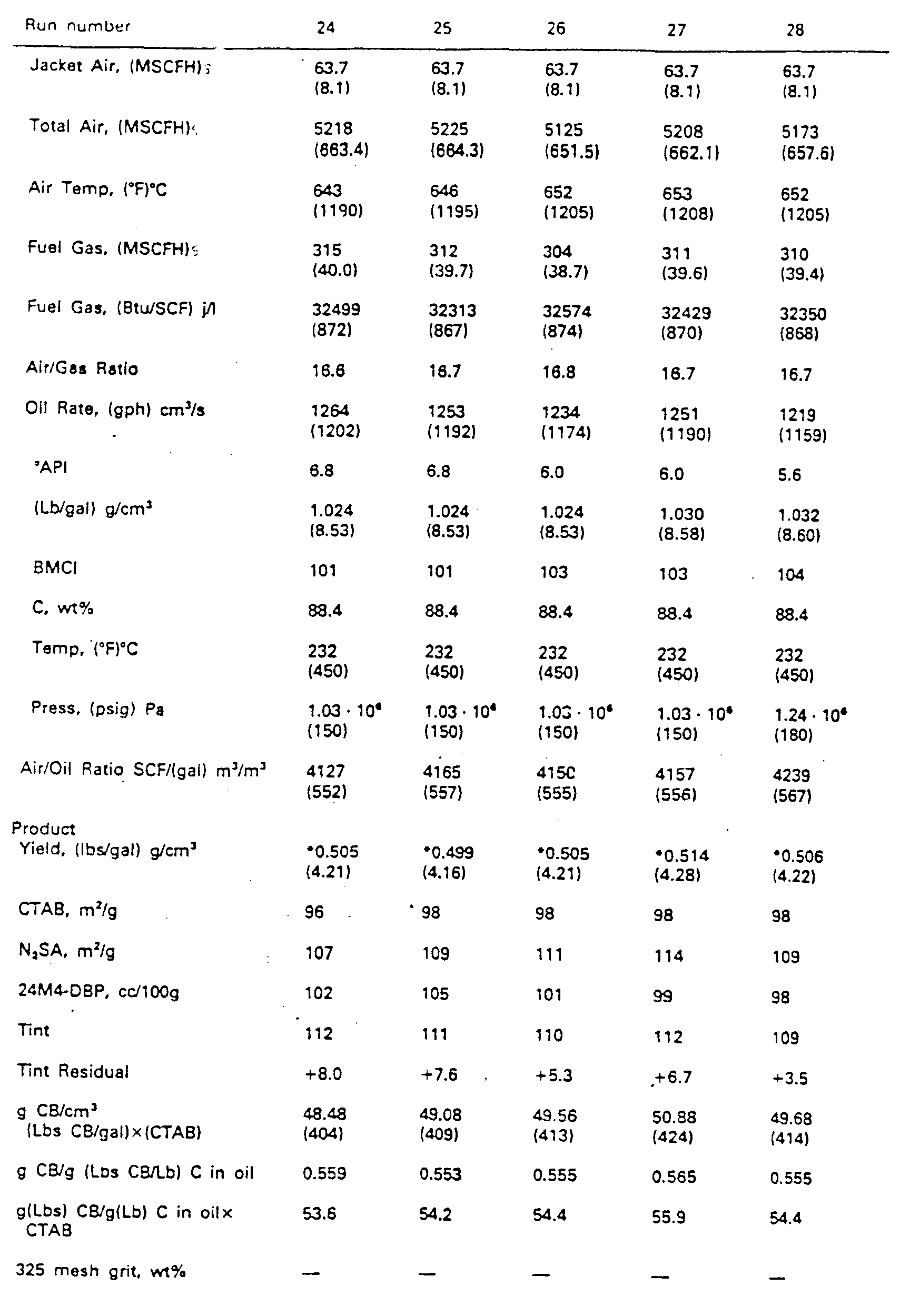
- Example II The runs were made in a commercial size plant reactor. A-J were measured in the same manner as in Example I. A is 71 cm (28 inches), B is 30 cm (12 inches), C is 52 cm (20.5 inches). D is 114.3 cm (3 feet 9 inches). E is 61 cm (2 feet). F is 10 cm (4 inches). G and H are shown in Table II. J is 46 cm (18 inches). K is the diameter of flange 29, which seals the end of gas tube 23, and is 10 inches. L is the length of ring 28, and is 14 inches. a is 18.43 ° (18 ° 26'). Results are shown in Table II.
- the photolometer values of blacks of Example II ranged from about 75 to about 90 (ASTM D 1618-80). Plant runs 19 through 46 show that different tread blacks are made (N299, N351 and N234) in the operations. Runs 19 through 34 used only jets. Runs 35 through 38 used jets and sprays. Runs 39 through 45 used all sprays. Run 46, again, used all jets.
- runs 37 and 38 Comparing runs 37, 38, and 39, producing N299 type carbon black, and using substantially the same operating conditions, runs 37 and 38 (all jets) produced 0.523 (4.36) and 0.516 (4.30) pounds g/cm 3 of carbon black per gallon) of oil, respectively, while run 39 (all sprays) produced 0.535 (4.46) g/cm 3 (pounds of carbon black per gallon) of oil. All had about the same tint residual of +4.6, +6.4 and +7.4, respectively. With the sprays of run 39, higher CTAB black was made (smaller nodules) and unexpectedly at higher yield, than in runs 37 and 38.
- Carbon blacks were dispersed in a 10-mM (10 millimolar) aqueous solution of sodium dioctylsulfosuc- cinate, an anionic surfactant trade named Aerosol OT (CAS Registry 577-11-7). The solution was cleaned by passing it through a 0.45- ⁇ m Millipore filter before use. Complete dispersion of the carbon blacks was accomplished with a magnetically stirred ultrasonic cleaning bath (U.S. 3,807,704, issued 1974, licensed to Lako Manufacturing Company). This bath combines mechanical stirring with ultrasonic agitation to obtain synergistic enhancement of rates of dispersion.
- a magnetically stirred ultrasonic cleaning bath U.S. 3,807,704, issued 1974, licensed to Lako Manufacturing Company. This bath combines mechanical stirring with ultrasonic agitation to obtain synergistic enhancement of rates of dispersion.
- the raw absorbance readings were converted to DODS obs values according to equation I.
- ⁇ is the wavelength in the suspension medium of refractive index m 2
- ⁇ ⁇ o /m 2
- ⁇ o the vacuum wavelength.
- m 2 1.324 + 3046/ ⁇ o 2 .
- the theoretical quantity DODS calc is matched with the observed quantity DODS obs using an iterative least-squares technique.
- the problem is to find the minimum of with respect to parameters of the carbon black aggregate size distribution f(X), and with respect to the complex refractive index, n-k ⁇ -1, of carbon black. Under the constraint this can be accomplished by means of a conventionally organized general-purpose nonlinear least-squares (Gause-Newton iterative variance minimization) computer program in which is embedded a fully rigorous Mie-theory subroutine for furnishing DODS calc function values and the necessary partial derivatives, the latter being obtained numerically.
- f(X) is a normalized particle diameter distribution function and N * denotes statistical degrees of freedom.
- DODS calc is where ⁇ C ext > is number-average extinction cross section of the carbon black aggregates, and ⁇ -ffX3/6> is their number average volume.
- C ext is calculated for each aggregate size X by Mie theory for a sphere of diameter X.
- the statistical distribution of X by frequency was assumed to be of log-normal form: where G is the breadth index for the distribution and Xg is the geometric mean of sphere diameters.
Landscapes
- Chemical & Material Sciences (AREA)
- Organic Chemistry (AREA)
- Pigments, Carbon Blacks, Or Wood Stains (AREA)
- Carbon And Carbon Compounds (AREA)
- Crystals, And After-Treatments Of Crystals (AREA)
- Compounds Of Iron (AREA)
- Compositions Of Macromolecular Compounds (AREA)
Abstract
Description
- In one aspect, the invention relates to new carbon black reactors. In another aspect, the invention relates to new methods for producing carbon black.
- Although commercial vortex flow reactors are adequate for today's needs, changes to provide greater economy and flexibility of operation and even higher quality product could be desirable.
- For example, improvements in the efficiency at which carbon black is produced from the feedstock would be very desirable. Also, the production of a carbon black product which contains exceptionally low levels of "grit" would be very desirable. The capability of producing carbon blacks having extremely positive or extremely negative tint residuals would also be desirable.
- In US-4 007 761 a carbon reactor is described. This reactor has a pyrolysis zone gently expanding from a throat in which zone carbon black is formed. The above-described objectives are not met by this prior art.
- US-A- 3 922 335 describes a process for producing carbon black and an apparatus suitable for use in this process. High speed combustion gases (at least Mach 0.35) are passed through an annular feedstock injection zone. The annular feedstock injection zone can be varied (col. 17, 1. 33 ff.) to square or rectangular cross-section and the feedstock can be injected from an axial feed nozzle radially outwardly and from the wall around the annular feedstock injection zone radially inwardly. For further acceleration of the combustion gases the reference provides that the combustion gases can be conducted from their producing chamber through constricted annular feedstock injection zone.
- US-A-4 077 761 describes a carbon black reactor with axial flow burner. A flow disrupting bluff body is provided in the flow stream of the oxidant upstream of the point of fuel injection.
- In accordance with the invention, the above objectives are satisfied by the carbon black reactor and process defined in the independent claims. Preferred embodiments are contained in the dependent claims.
- The present invention allows the production of a carbon black characterized by a CTAB surface area of between about 50 and 500 m2/g and an aggregate size distribution breadth index G of 1.85 or greater. This type of carbon black imparts low hysteresis properties to rubber into which it has been compounded and can therefore be very desirable for the production of belts and tires, for example.
- In another aspect, the present invention allows the production of a carbon black characterized by a CTAB surface area of between about 50 and 500 m2/g and an aggregate size distribution breadth index G of 1.20 or less. This type of carbon black has a high positive tint residual value which imparts high abrasion resistance in tires.
- The reactor of this invention is well-adapted for producing carbon black at high yields and low grit levels.
- The process of producing carbon black in accordance with this invention when introducing the carbonaceous feedstock as a coherent stream into the converging zone, results in greater yields of product which has a higher tint residual. If employing an embodiment comprising introducing the carbonaceous feedstock into the throat within a distance of about 10 cm (4 inches) from the abruptly diverging zone this results in the production of low or negative tint residual black which imparts low hysteresis to rubber into which it has been compounded.
- In another aspect of the present invention there is provided for a process as defined in the claims of producing carbon black comprising flowing a stream of hot combustion gases having a temperature sufficiently high to decompose a carbonaceous feedstock and form carbon black sequentially through a converging zone, a throat and an abruptly diverging zone and introducing the carbonaceous feedstock transversely into the stream of hot combustion gases from the periphery of the stream for decomposition to form the carbon black, the improvement comprising introducing the carbonaceous feedstock into the stream of hot combustion gases as a coherent stream having a velocity component counter to the flow of the stream of hot combustion gases.
- In still another aspect of the present invention there is provided for a process as defined in the claims of producing carbon black comprising flowing a stream of hot combustion gases having a temperature sufficiently high to decompose a carbonaceous feedstock and form carbon black sequentially through a converging zone, a throat and an abruptly diverging zone and introducing the carbonaceous feedstock transversely into the stream of hot combustion gases from the periphery of the stream for decomposition to form the carbon black, the improvement comprising introducing the carbonaceous feedstock as a spray into at least one of the converging zone and the throat. The improvement step results in the production of carbon black at higher efficiency than where coherent streams of feedstock are utilized.
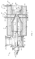
- The Figure illustrates certain features of one embodiment of the present invention.
- According to the invention, an
apparatus 2 comprises, serially arranged, acombustion zone 4, amixing zone 6, and a pyrolysis zone 8. - The
combustion zone 4 comprises acombustion chamber 10 defined by a generally cylindrical sidewall 12 and a generally annular upstream end wall 14 having apassage 16 therethrough generally axially directed into the generallycylindrical combustion chamber 10. The sidewall 12 and endwall 14 are generally formed from a refractory material to resist high temperatures. Oxidant fluid and combustible fluid are introduced into thechamber 10 via thepassage 16. Preferably, thepassage 16 leads fromchamber 18 which is defined by ahousing 20. Thehousing 20 can be formed from metal, such as steel, and preferably comprises a generallytubular sidewall 21 so that thechamber 18 is generally cylindrical as it extends from thepassage 16, preferably in axial alignment therewith. Atubular member 23 extends through thechamber 18 axially and empties into thepassage 16. - The
tubular member 23 carries the combustible fluid which is mixed with oxidant fluid from thechamber 18 in thepassage 16. Thehousing 20 is closed at its upstream end by aplate 24 affixed to aflange 26 which circumscribes the upstream end of thehousing 20. Thetubular member 23 enters thechamber 18 in an axial direction through theplate 24. An annulus 19 defined between theplate 24 and thetubular member 23 provides a passage for the introduction of coolant, such as a cool gas, into thechamber 18 to protect the metal components in the neighborhood offlange 24 from high temperatures. Aduct 27 opens into thechamber 18 through thesidewall 21. Theduct 27 can open into thechamber 18 tangentially if desired, although a duct opening into thechamber 18 generally normally with respect to the longitudinal axis of thechamber 18 has been used with good results. - Preferably, the generally annular surface 14 is a part of a ring or
choke 28 positioned between thechambers passage 16, because the ring helps to distribute oxidant fluid from thechamber 18 into thechamber 10. Thering 28 can be formed from a section of tubular refractory. Thetubular member 23 preferably empties into thepassage 16 through a plurality of radially outwardly directed ports ororifices 30 passing through the sidewall of thetubular member 23 where a gaseous combustible fluid is utilized, for ease of fabrication and reliability of operation. A bluff body, in the form of a generallyannular flange 29 is attached to thetubular member 23 slightly downstream of theports 30 to aid in maintaining stable combustion. Preferably, theflange 29 is positioned upstream of the surface 14, most preferably about 5 cm (2 inches) into thezone 16, as measured fromzone 18. - Generally, the reaction flow passage expands between the
passage 16 and thezone 10 from a first diameter to a second diameter such that the ratio between the first diameter and the second diameter is between about 0.3 and about 0.8. Usually, the ratio of the diameters of theflange 29 and thepassage 16 is within the range of from about 0.5 to about 0.75. - The
mixing zone 6 comprises a sidewall 31 formed from refractory defining achamber 32 in axial alignment with and converging from thecombustion chamber 10 to a throat 34 and ameans 36 for introducing a carbonaceous feestock through the sidewall 31 and into at least one of theconverging chamber 32 and the throat 34. Preferably, theconverging chamber 32 converges from an inlet having a diameter about the same as that of thecombustion chamber 10 to an outlet having a diameter about the same as that of the throat 34. A converging chamber which converges at a half-angle of about 18.5 (18° 30') has been used with good results. Themeans 36 comprises one or more sets ofports 38, which open into thechamber 32, more preferably, 2 or more sets ofports 38 with at least one set opening into theconverging chamber 32 and at least one sat opening into the throat 34 for the positioning ofcarbonaceous feedstock injectors 40. Usually, the ports of a set will be circumferentially spaced about the reaction flow passage at a selected position with respect to the longitudinal axis of the reaction flow passage, with the ports being preferably equiangularly spaced from each other for uniform distribution of feestock from theinjectors 40 and into the reaction flow passage. Generally, each set ofports 38 will be arranged in equiangular spacing, for example, 1800, 1200, 900, or 600, and be radially inwardly directed, although they can be canted upstream or downstream as desired. Ports not in use can be sealed withplugs 41. Usually, theinjectors 40 will be positioned through only one set of theports 38 so that they empty into the flow passage of the reactor at the same longitudinal position. As injectors are moved upstream, the structure of the black increases. Preferably, the tip of each injector is positioned about flush with the reactor wall, to lessen heat exposure and cut down on coking and plugging. - Alternatively, the
injectors 40 can be provided withnozzles 43 which can be canted to introduce carbonaceous feedstock into the reaction flow passage with an upstream or downstream velocity component as desired. Thenozzles 43 can be selected to introduce the feedstock as a coherent stream or a spray or any other pattern as desired. When the feedstock is introduced into the reactor in a partially upstream or downstream direction, preferably upstream with a component counter current to the flow of combustion gases to improve mixing it is preferred that the nozzles be selected to emit a coherent stream of feedstock, so that the dissociation of the feedstock will take place away from the reactor wall and the penetration of the feedstock will be sufficient to cause good distribution of dissociated carbonaceous material across the reaction flow path. Where the feedstock is to be introduced generally normally into the reactor with respect to its axis, it is currently preferred to utilize nozzles which are designed to emit a spray, although spray nozzles are also advantageous where the nozzles are canted, especially when the nozzles are canted to emit feedstock in a downstream direction. It appears that when spray-stream nozzles are used, product yield from the reactor is enhanced over the solid-stream nozzles are used. Solid-cone type spray nozzles, which emit atomized feedstock at an angle of divergence of about 150 have been used with good results. Jacket cooling air, not shown, can surround theoil injectors 40, flowing through the annulus between the oil tube and the wall of the port. - When the apparatus is operated with carbonaceous feedstock injection into the throat 34, carbon black having a wide aggregate size distribution can be produced. Generally, for this type of operation, the feedstock injectors will be positioned about 0-10 cm (0-4 inches), for example between 2.5 and 7.5 cm (1 and 3 inches), upstream of the pyrolysis zone. Such a carbon black is frequently characterized by a negative tint residual and will impart low hystersis to rubber into which it has been compounded. When the apparatus is operated with feedstock injection into the converging
chamber 32, carbon black having a very narrow aggregate size distribution can be produced. Such a carbon black is frequently characterized by a high or positive tint residual. Generally, for this type of operation, the feedstock oroil injectors 40 will be positioned between about 10 cm (4 inches) and about 91 cm (36 inches) upstream of the pyrolysis zone. usually between about 15 (6) and about 61 cm (24 inches) upstream. - If desired, carbonaceous feedstock can also be injected into the converging
chamber 32 and/or throat 34 via optional axialfeedstock injector assembly 42, which can be fitted with an appropriate nozzle to dispense liquid or vaporous, preferably liquid, carbonaceous feedstock. In some operations,tube 42 is not installed, however, in the preferred embodiment of this aspect of the invention, theassembly 42, which preferably comprises afeedstock tube 47 coaxially disposed within a water-jacket tube 45, enters thereactor 2 coaxially within thegas tube 23 and extends adjustably from the end of thetube 23 at least into the convergingchamber 32. Thefeedstock tube 47 can be fitted with any one of a variety of feedstock nozzles, for example, single or multiple solid jet nozzles with the jets directed axially, radially outwardly, or at an angle, or a solid or a hollow cone nozzle, etc., as desired. - The pyrolysis zone 8 preferably is comprised of one or more generally cylindrical sections of
refractory material 44. The mixingzone 6 is preferably a separate section of refractory, so that it can be easily replaced if desired. - Because of very high temperatures in zone 8, heavy-duty refractory, such as chrome-alumina refractory (minimum 9 wt.% Cr203) manufactured by Didier-Taylor, Cincinnati, Ohio, is preferably employed for at least the construction of the zone 8.
- It is desired to generate high turbulance in the reaction mixture when it passes from the mixing
zone 6 to the pyrolysis zone 8, to disintegrate the carbonaceous feedstock to form high quality carbon black. It is therefore very important that the reaction flow passage undergo an abrupt expansion as it enters the pyrolysis zone from the mixing zone. Preferably, the half-angle of expansion is near 900, because this configuration has been used with good results. - Preferably, the upstream end of the pyrolysis zone is defined by a generally annularly
shaped end wall 46 which extends from the downstream end of the throat 34 to the upstream end ofpyrolysis zone sidewall 48. The pyrolysis zone preferably has a generally circular cross-section in a plane normal to the axis of the reaction flow passage. The desired amount of expansion between the zones will depend on reactor flow conditions and the desired properties of the carbon black to be produced. Generally, the cross sectional area of the reaction flow passage defined bysidewall 48 in a plane normal to the reactor axis will be in the range of from about 2.8 to about 13 times larger than the cross sectional area of the reaction passage at the throat 34. An expansion ratio toward the lower end of this range tends to provide a carbon black product characterized by higher surface area and lower structure, while an expansion ratio toward the upper end of the range provides a carbon black product characterized by lower surface area and higher structure. - Where the production of a carbon black product characterized by higher structure is desired, the pyrolysis zone is provided with a plurality of abrupt expansions in the reaction flow passage. In the Figure, the upstream end of the pyrolysis zone 8 comprises serially arranged from the upstream end wall 46 a first generally
cylindrical zone 50 having a first diameter and a second generallycylindrical zone 52 having a second diameter which is larger than the first diameter. Preferably, the first generallycylindrical zone 50 has a diameter sufficient so that the area ratio between the first generallycylindrical zone 50 and the throat 34 is in the range of from about 2.8:1 to about 13:1. The flow area ratio between the second generallycylindrical zone 52 and the first generallycylindrical zone 50 is preferably from about 1:1 to about 4:1. The first generallycylindrical zone 50 preferably has a length in the range of from about 0.1 to about 15 times the diameter of the throat 34, usually from about 0.5 to about 10 diameters. Preferably, anannular shoulder 54 separates thezones - The pyrolysis zone 8 is further provided with a
means 56 for supplying cooling fluid to the reaction flow passage. Generally, themeans 56 comprisesports 58 opening into the pyrolysis zone 8. Preferably, at least one of theports 58 carries a tube andspray nozzle assembly 60 for introducing a quench fluid into the zone 8 to stop the pyrolysis reaction. Generally, themeans 56 will be positioned downstream of the outlet of the throat at a distance of from about 5 to about 45 throat diameters, usually at a distance of between about 8 and about 20 throat diameters. In other terms, themeans 56 will be positioned between about 0.5 m (1.5 feet) and about 6 m (20 feet) downstream of the throat. Positioning themeans 56 close to the throat produces low photolometer product. Usually, themeans 56 is positioned downstream from the throat at a distance to produce a photolometer value of at least about 70 and is preferably designed to spray water. Further downstream of the quench means 56, the reaction mixture is further cooled to facilitate handling, and can be processed in conventional equipment. - Certain aspects of the invention are carried out according to a process comprising flowing a stream of hot combustion gases having a temperature sufficiently high to decompose a carbonaceous feedstock and form carbon black sequentially through a converging zone, a throat and an abruptly diverging zone: and introducing the carbonaceous feedstock transversely into the stream of hot combustion gases from the periphery of the stream for decomposition to form the carbon black.
- Generally, the oxidant fluid comprises air, since it is inexpensive and plentiful, preferably preheated air at a temperature of from about 371 (700) to about 677 ° C (1250°F), since employing preheated air is an inexpensive method of supplying heat to the reactor to drive the pyrolysis reaction and aids in forming a high-structure product. Of course, pure oxygen or oxygen-enriched air is also suitable, and besides having the advantage of producing a higher structure product, is the preferred oxidant where a low BTU fuel is burned.
- Generally, the combustible fluid will comprise mostly methane, because methane is the major component of natural gas and synthetic natural gas and these materials are suitable combustible fluids and are inexpensive. Other combustible fluids, containing one or more components, for example selected from hydrogen, carbon monoxide, acetylene and propane are also suitable. An inexpensive fuel commonly found in a carbon black plant comprises off-gases from the filter bags, especially from soft black manufacture. This fuel is a low-BTU fuel, containing about 100 BTU/SCF, and generally 25-30 vol% or so of H2 and CO.
- Liquid fuels such as are used in some conventional carbon black plants can also be used in the present invention. In some plants part, of the feedstock is used as fuel.
- Generally, stoichiometric or excess air is mixed with the combustible fluid and ignited as the mixture is introduced into the combustion zone. By stoichiometric is meant an amount which results in the essential absence of both molecular oxygen and combustible materials in the combustion gases. A greater than stoichiometric amount of air, commonly called "excess" air, will result in the presence of reactive oxygen in the combustion gases. Fifty percent excess air is frequently used in carbon black manufacturing processes, and this means that 150% of the stoichiometric amount of air has been mixed with the combustible fluid.
- Of course, the "excess" air partly consumes the carbonaceous feedstock and therefore results in lost yield. These are at least two reasons, however, why its presence can be desirable. First, as the excess air reacts with the feedstock, it generates both turbulence and heat, and therefore a finer and more uniform carbon black product. Secondly, the excess air dilutes the combustion gases and reduces their temperature, protecting equipment. However, where the reactor is capable of withstanding the temperatures of near stoichiometric combustion of the air and fuel and concommitantly generates sufficient turbulence downstream of the feedstock injection to form the desired particle size of carbon black, and the combustion gas stream contains sufficient heat to pyrolyze the feedstock particles, excess air can be avoided, since it results in reduced yields due to combustion of a portion of the feedstock.
- Where natural gas is used as the combustible fluid, it is preferably mixed with air at a volume ratio of from about 10:1, which is near stoichiometric, to about 20:1, which would be about 100% excess air. At reactor conditions, the combustion gases pass through the throat at a temperature in the range of 1300-1650 ° C (2400-3000 ° F), and at a velocity generally in the range of 60-340 ms-1 (Mach 0.2-1.0), usually between about 100 (0.3) to about 140 (0.7). Mach 1 in feet per second is roughly equal to 49.01 vlT, where T is the temperature in ° R (Rankine) at reactor conditions. (T°R=T°F+460). Higher temperatures and velocities yield desirable products, but cause unduly expensive operation.
- The carbonaceous feedstock which is injected into the combustion gas stream from its periphery is generally any of the hydrocarbon feeds suitable for forming carbon black. Generally, the carbonaceous feedstock will be a liquid, contain about 90 weight percent carbon and have a density greater than that of water. Preferably, the feedstock will be characterized by a Bureau of Mines Correlation Index, BMCI of between about 90 and about 150. The carbonaceous feedstock is preferably preheated to a temperature in the range of 120 (250) to about 260 ° C (500 ° F) prior to injection into the combustion gases. It is important that the streams of feedstock do not penetrate sufficiently far to impinge on the wall of the reactor. However, to insure adequate dispersal, it is preferred that the feedstock be injected at a pressure of at least 3.4 . 10-5 Pa (50 psig). If desired, the same carbonaceous feedstock can also be introduced into the reactor from a position along the reactor axis. It will be appreciated that injecting the feedstock through a smaller orifice requires a higher pressure to achieve the same penetration.
- According to the present invention, the carbonaceous feedstock is introduced into the converging zone from the periphery thereof.
- By injecting the carbonaceous feedstock transversely into the converging combustion gases, there can be provided a carbon black product having a CTAB surface area in the range of between about 50 and about 500 m2/g, usually between about 50 and about 200 m2/g, most preferably between about 70 and 150 m2/g, which is characterized by a "G index" value of less than about 1.2, between about 1.0 and 1.2, such as between 1.1 and 1.2 preferbaly between 1.15 and 1.20. This type of carbon black can be characterized by a tint residual of about plus 12 or greater and occasionally plus 16 or greater (See tabulated runs in subsequent tables). Such a carbon black can be usefully compounded into rubber to impart certain desirable properties thereto. The CTAB surface area of a carbon black sample is measured in accordance with ASTM and is generally considered to have a correlation with the surface area of the carbon black sample available for reinforcing rubber. The "G index" value is calculated in accordance with Applied Optics 19, 2977 (1980) and as herein described in (Example III and correlates with the breadth of distribution of the aggregate particle sizes in the sample. A "G index" value of less than 1.25 indicates an extremely homogeneous product, with the sizes of the appregates being extremely uniform, relatively speaking. "Conventional" furnace blacks have a "G index" value in the range of about 1.4-1.6.
- The carbonaceous feedstock can be introduced into the converging zone either as a coherent stream or as a spray, as desired. Preferably, the feedstock is introduced as a spray, because testing shows that spraying the feedstock into the reactor results in the higher yield of product. The feedstock can be introduced into the converging zone in a direction normal to the axis of the reactor flow path, which is preferred, since it has been tested with good results, or it can be introduced into the combustion gases with a flow component cocurrent or countercurrent to the combustion gas flow. Where the feedstock is to be introduced into the reactor with a flow component countercurrent to the flow of the combustion gas stream, it may be desirable to utilize a coherent stream of feedstock, to mitigate impingement of feedstock on the reactor wall.
- According to another aspect of the invention the carbonaceous feedstock is sprayed inwardly into the combustion gas stream flowing through the reactor throat, preferably radially inwardly, or, if desired, canted in the upstream or preferably, the downstream direction. Spraying the feedstock into the throat as a mist produces a higher surface area product than injecting coherent streams of feedstock into the throat under reactor conditions which are otherwise the same. Because the invention in this embodiment provides a method raising the surface area of the carbon black product at no increase in operating costs, it is a significant advance in the art.
- In another aspect of the present invention, by introducing the carbonaceous feedstock radially inwardly transversely into the combustion gas stream downstream of the inlet to the converging section at a distance upstream of the pyrolysis section in the range of from about 0.05 to 0.9 throat diameters, preferably in the range of 0-10 cm (0-4 inches) upstream of the pyrolysis zone, more preferably in the range of 2.5-7.5 cm (1-3 inches) upstream of the pyrolysis zone, such as about 3.8 cm (1.5 inches) upstream of the pyrolysis zone, there can be provided a carbon black product having a CTAB surface area in the range of between about 50 and about 500 m2/g, usually between about 50 and about 200 m2/g, preferably between about 70 and about 150 m2/g, which is characterized by a "G index" value of greater than about 1.85, preferably greater than about 2, such as in the range of 2 to 3, preferably between about 2.25 and about 2.75. This type of carbon black can be characterized by a tint residual value of minus 12 or lower and occasionally minus 16 or lower (See tabulated runs in subsequent tables). A carbon black characterized by high "G index" value has a broad aggregate size distribution and imparts low hysteresis properties to rubber into which it has been compounded. This carbon black will impart low rolling resistance to vehicular tires when it has been compounded into the rubber which forms them.
- The invention is illustrated by the following Examples.
- The runs were made in a pilot plant reactor. A is the diameter of
zone 10. B is the diameter of throat 34. C is the diameter ofzone 52. D is the length ofzone 10. E is the length ofzone 32. a is the angle at which the sidewall ofzone 32 converges toward the longitudinal axis of the reactor. F is the length of throat 34. G is the length ofzone 52 fromwall 46 to quench 60. H is the distance ofoil injectors 40 upstream fromwall 46, and J is the diameter ofzone 16. The gas burner upstream ofzone 10 was modified from that shown by the figure as follows: - Premixed air and fuel were supplied axially into the
passage 16 through the end of a tube having a 10 cm (4 inch) inside diameter and terminating 5 cm (2") upstream of wall 14. The end of the tube was partially closed by a radially inwardly extending annular flange having an inside diameter of 6.3 cm (2.5 inches). Results are shown in Table I.


- (a) This is a two stage or stepped zone. The 7.6 cm ;3 inch) diameter zone was 23 cm (9 inches) in length for run 5. and the 15 cm (6 inch) diameter zone was 76 cm (30 inches) in length to quench injection.
- (b) This is a two stage or stepped zone. The 15 cm (6 inch) diameter zone was 96 cm (38 inches) long in both runs 16 and 17, and the 20 cm (8 inch) diameter zone was 86 cm (34 inches) in length for both runs:
- "' 3 nozzles spaced at 90°. Two nozzles are 180° apart, with the third nozzle in between at 90° from the two nozzles which are 180° apart.
-
Runs 1, 2 and 3 show decreases in air-to-oil ratio, SCF/cm3(gallon), of 0.198 (750), 0,181 (685) and 0.166 (630), respectively; decreases in diameter of zone C, in cm (inches), of 15 (6) 10 (4), and 7.6 (3), respectively; increases in H, in inches of 3.8 (1.5), 3.8 (1.5), and 16.5 (6.5), respectively; and increases in F, in inches, of 3.8 (1.5), 8.9 (3.5), and 8.9 (3.5), respectively, cause increased carbon black production, in g/s (pounds par hour), of from 11.03 (87.5) to 12.15 (96.4), to 13.43 (106.6), respectively, with increases in g/cm3 (pounds of carbon black per gallon) of feed oil from 0.562 (4.68), to 0.564 (4.7), to 0.576 (4.8), respectively. The CTAB values, in m2/g, would be expected to decrease from run 1 through run 3 because of the decreases in air-to-oil ratio from run 1 through run 3. However, run 1 and run 3 had the same 108 CTAB values, and, unexpectedly, run 2 had a very high CTAB value of 115. The 24M4 values, in cc/100g., decreased from 111 to 96 to 94, respectively from run 1 through run 3, due to these changes. - When the air preheat was increased from 413°C for run 3 to 563 ° C for
run 4, the production of carbon black increased from 0.58 to 0.62 (4.8 to 5.2) g/cm3 (pounds of carbon black per gallon) of feedstock. The CTAB values remained about the same, and the tint residuals were about the same at +8.9 and +7.2, respectively. -
Runs 4 and 5 shows that changing the dimensions of C, using a 7.6 cm (3 inch) diameter throughout for 255 cm (72 inches) inrun 4, but using C of 7.6 cm (3 inches) diameter for 23 cm (9 inches) and then 15 cm (6 inches) in diameter for 76 cm (30 inches) to quench for run 5, there resulted in an extremely large gain in 24M4 value for run 5 from 94 forrun 4 to 106 for run 5, at about the same CTAB values and at about the same tint residuals. In addition, the change in C in run 5 increased the yield of carbon black in g/cm3 (pounds per gallon) of oil, this quantity being 0.624 (5.2) forrun 4 and 0.636 (5.3) for run 5. Runs, 1, 2 and 3 had values of 0.562 (4.68) 0.564 (4.7) and 0.576 (4.8), respectively, for carbon black yields in g/cm3 (pounds per gallon). -
Runs 6 through 15 show the effects of the position of the oil injection H on tint residuals.Runs 6 and 7 had H values of 4 cm (1.5 inches), the oil being added 4 cm (1.5 inches) upstream from the throat outlet, and the tint residuals were -15.3 and -16.1, respectively, for runs 6 and 7. The H values for runs 14 and 15 were 11.4 (4.5) and 16.5 cm (6.5 inches) upstream from the throat outlet, respectively, and the tint residuals were + 14.6 and + 10.5, respectively, for runs 14 and 15. This change in H shows the flexibility of the operation for producing carbon blacks of broad aggregate distribution (runs 6 and 7) and of narrow aggregate size distribution (runs 14 and 15). -
Runs 16 and 17 used the two-step reaction zone, as disclosed, and with H values of 4 cm (1.5 inches), produced tint residuals of -10.9 and -14.8, respectively, using the different nozzle arrangement as compared with runs 1 through 15, as defined herein. The CTAB values were 85 and 67, respectively, using air-to-oil ratios of 530 and 475, respectively, for runs 16 and 17, and tint residuals of -10.9 and -14.8, respectively. - Run 18 used a on-step or 15 cm (6 inch) diameter zone C for the reactor and used the same nozzle arrangement as in runs 16 and 17, with H of 4 cm (1.5 inches), and produced a tint residual of -6.8.
- The runs were made in a commercial size plant reactor. A-J were measured in the same manner as in Example I. A is 71 cm (28 inches), B is 30 cm (12 inches), C is 52 cm (20.5 inches). D is 114.3 cm (3 feet 9 inches). E is 61 cm (2 feet). F is 10 cm (4 inches). G and H are shown in Table II. J is 46 cm (18 inches). K is the diameter of
flange 29, which seals the end ofgas tube 23, and is 10 inches. L is the length ofring 28, and is 14 inches. a is 18.43 ° (18 ° 26'). Results are shown in Table II.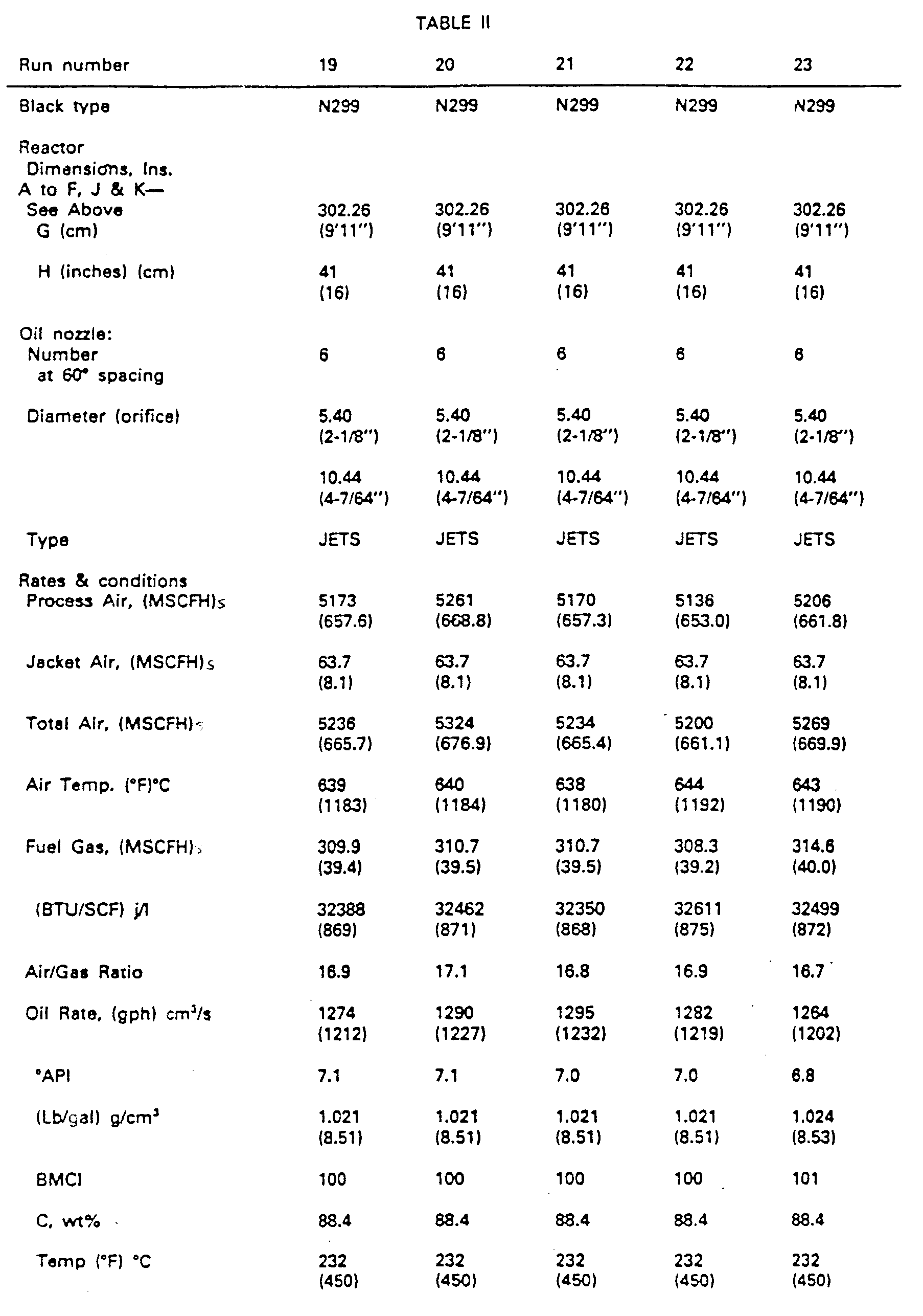


- The photolometer values of blacks of Example II ranged from about 75 to about 90 (ASTM D 1618-80). Plant runs 19 through 46 show that different tread blacks are made (N299, N351 and N234) in the operations. Runs 19 through 34 used only jets. Runs 35 through 38 used jets and sprays. Runs 39 through 45 used all sprays.
Run 46, again, used all jets. - Comparing runs 37, 38, and 39, producing N299 type carbon black, and using substantially the same operating conditions, runs 37 and 38 (all jets) produced 0.523 (4.36) and 0.516 (4.30) pounds g/cm3 of carbon black per gallon) of oil, respectively, while run 39 (all sprays) produced 0.535 (4.46) g/cm3 (pounds of carbon black per gallon) of oil. All had about the same tint residual of +4.6, +6.4 and +7.4, respectively. With the sprays of run 39, higher CTAB black was made (smaller nodules) and unexpectedly at higher yield, than in
runs 37 and 38. - Samples of the blacks obtained from
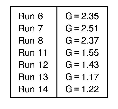
runs 6, 7, 8, 11, 12, 13 and 14 above were analyzed according to the following procedure. - Carbon blacks were dispersed in a 10-mM (10 millimolar) aqueous solution of sodium dioctylsulfosuc- cinate, an anionic surfactant trade named Aerosol OT (CAS Registry 577-11-7). The solution was cleaned by passing it through a 0.45-µm Millipore filter before use. Complete dispersion of the carbon blacks was accomplished with a magnetically stirred ultrasonic cleaning bath (U.S. 3,807,704, issued 1974, licensed to Lako Manufacturing Company). This bath combines mechanical stirring with ultrasonic agitation to obtain synergistic enhancement of rates of dispersion. Masterbatch slurries at concentrations of about 2 mg per milliliter (50 mg of black plus 25 milliliters of liquid) were initially treated 30 minutes in the bath. These were then diluted 100-fold (250 µ liter of slurry plus 25 milliliters of liquid) and further sonified for 150 minutes. All masses and volumes were determined by weighing on a five-place analytical balance: precise concentrations c (µg/milliliter) were calculated from these weights.
- Measurements were made of "dimensionless optical density spectra" defined as

- Optical absorbance readings, log (Io/I), where 10 is incident intensity and I is transmitted intensity, were obtained at 50-nm intervals in incident wavelength Ào from 350 to 1000 nm using a Beckman Model B spectrophotometer and cuvettes having optical path length b = 10.0 mm. The raw absorbance readings were converted to DODSobs values according to equation I. \ is the wavelength in the suspension medium of refractive index m2, and λ=λo/m2, where λo is the vacuum wavelength. For the aqueous medium used, m2 = 1.324 + 3046/λo 2.
- To determine G, the theoretical quantity DODScalc is matched with the observed quantity DODSobs using an iterative least-squares technique. The problem is to find the minimum of

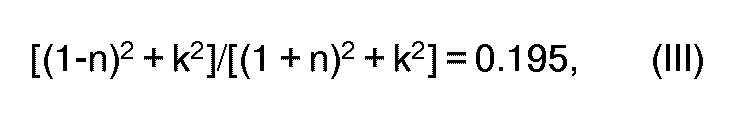


- The carbon black samples analyzed exhibited the following "G" values

Claims (7)
Priority Applications (1)
| Application Number | Priority Date | Filing Date | Title |
|---|---|---|---|
| AT83108439T ATE33668T1 (en) | 1982-08-30 | 1983-08-26 | METHOD AND DEVICE FOR THE PRODUCTION OF SOOT. |
Applications Claiming Priority (2)
| Application Number | Priority Date | Filing Date | Title |
|---|---|---|---|
| US41320282A | 1982-08-30 | 1982-08-30 | |
| US413202 | 1982-08-30 |
Publications (4)
| Publication Number | Publication Date |
|---|---|
| EP0102072A2 EP0102072A2 (en) | 1984-03-07 |
| EP0102072A3 EP0102072A3 (en) | 1984-09-26 |
| EP0102072B1 EP0102072B1 (en) | 1988-04-20 |
| EP0102072B2 true EP0102072B2 (en) | 1995-04-12 |
Family
ID=23636281
Family Applications (1)
| Application Number | Title | Priority Date | Filing Date |
|---|---|---|---|
| EP83108439A Expired - Lifetime EP0102072B2 (en) | 1982-08-30 | 1983-08-26 | Method and apparatus for the production of carbon blacks |
Country Status (10)
| Country | Link |
|---|---|
| EP (1) | EP0102072B2 (en) |
| AT (1) | ATE33668T1 (en) |
| BR (1) | BR8304651A (en) |
| CA (1) | CA1259164A (en) |
| DE (1) | DE3376335D1 (en) |
| ES (1) | ES8507168A1 (en) |
| IN (1) | IN160110B (en) |
| MX (1) | MX161632A (en) |
| TR (1) | TR22021A (en) |
| ZA (1) | ZA836198B (en) |
Families Citing this family (15)
| Publication number | Priority date | Publication date | Assignee | Title |
|---|---|---|---|---|
| CA1258157A (en) * | 1983-09-20 | 1989-08-08 | Mark L. Gravley | Carbon blacks and method and apparatus for their production |
| DE3443872A1 (en) * | 1983-12-23 | 1985-07-04 | Cabot Corp., Boston, Mass. | METHOD FOR THE PRODUCTION OF FURNACE RUSS |
| US4645657A (en) * | 1983-12-23 | 1987-02-24 | Cabot Corporation | Production of carbon black |
| US4582695A (en) * | 1984-09-19 | 1986-04-15 | Phillips Petroleum Company | Process for producing carbon black |
| TR22401A (en) * | 1984-10-10 | 1987-04-08 | Phillips Petroleum Co | PROCEDURE AND DEVICE FOR NEW CARBON BLACK AND MANUFACTURED |
| US4643880A (en) * | 1984-12-14 | 1987-02-17 | Phillips Petroleum Company | Apparatus and process for carbon black production |
| US4664901A (en) * | 1985-03-04 | 1987-05-12 | Phillips Petroleum Company | Process for producing carbon black |
| CA1300342C (en) * | 1985-06-24 | 1992-05-12 | E. Webb Henderson | Process and apparatus for producing carbon black |
| US4822588A (en) * | 1985-07-26 | 1989-04-18 | Phillips Petroleum Company | Process for producing carbon black |
| JP2835751B2 (en) * | 1989-11-02 | 1998-12-14 | 東海カーボン株式会社 | Method for producing carbon black |
| US6228928B1 (en) | 1990-07-25 | 2001-05-08 | Cabot Corporation | Carbon black and rubber composition containing same |
| JP2903097B2 (en) * | 1990-07-25 | 1999-06-07 | 昭和キャボット株式会社 | Carbon black and rubber composition containing the same |
| US5232974A (en) * | 1991-11-25 | 1993-08-03 | Cabot Corporation | Low rolling resistance/high treadwear resistance carbon blacks |
| DE102008043606A1 (en) | 2008-11-10 | 2010-05-12 | Evonik Degussa Gmbh | Energy-efficient plant for the production of carbon black, preferably as an energetic composite with plants for the production of silicon dioxide and / or silicon |
| CN109777158A (en) * | 2019-03-05 | 2019-05-21 | 云南云维飞虎化工有限公司 | A New Type of Carbon Black Reactor |
Family Cites Families (3)
| Publication number | Priority date | Publication date | Assignee | Title |
|---|---|---|---|---|
| US3077761A (en) * | 1959-12-07 | 1963-02-19 | Prime Mfg Co | Pressure gage mounting apparatus |
| US4341750A (en) * | 1977-06-20 | 1982-07-27 | Phillips Petroleum Company | Carbon black production |
| US4339422A (en) * | 1980-10-16 | 1982-07-13 | Phillips Petroleum Company | Carbon black manufacture |
-
1983
- 1983-06-02 CA CA000429499A patent/CA1259164A/en not_active Expired
- 1983-08-22 ZA ZA836198A patent/ZA836198B/en unknown
- 1983-08-24 TR TR22021A patent/TR22021A/en unknown
- 1983-08-25 IN IN1039/CAL/83A patent/IN160110B/en unknown
- 1983-08-26 AT AT83108439T patent/ATE33668T1/en not_active IP Right Cessation
- 1983-08-26 EP EP83108439A patent/EP0102072B2/en not_active Expired - Lifetime
- 1983-08-26 DE DE8383108439T patent/DE3376335D1/en not_active Expired
- 1983-08-29 BR BR8304651A patent/BR8304651A/en not_active IP Right Cessation
- 1983-08-29 ES ES525216A patent/ES8507168A1/en not_active Expired
- 1983-08-30 MX MX198562A patent/MX161632A/en unknown
Also Published As
| Publication number | Publication date |
|---|---|
| MX161632A (en) | 1990-11-27 |
| EP0102072A2 (en) | 1984-03-07 |
| ZA836198B (en) | 1984-04-25 |
| EP0102072B1 (en) | 1988-04-20 |
| ATE33668T1 (en) | 1988-05-15 |
| DE3376335D1 (en) | 1988-05-26 |
| BR8304651A (en) | 1984-04-10 |
| ES525216A0 (en) | 1985-08-16 |
| EP0102072A3 (en) | 1984-09-26 |
| CA1259164A (en) | 1989-09-12 |
| TR22021A (en) | 1986-01-13 |
| ES8507168A1 (en) | 1985-08-16 |
| IN160110B (en) | 1987-06-27 |
Similar Documents
| Publication | Publication Date | Title |
|---|---|---|
| US4765964A (en) | Carbon black reactor having a reactor throat | |
| US4540560A (en) | Carbon blacks | |
| EP0102072B2 (en) | Method and apparatus for the production of carbon blacks | |
| CA2100350C (en) | Production of carbon blacks | |
| US3922335A (en) | Process for producing carbon black | |
| EP0136629B1 (en) | Novel carbon blacks and method and apparatus for their production | |
| US4645129A (en) | Atomizing nozzle and use | |
| US5252297A (en) | Process for producing carbon black and apparatus therefor | |
| CS199269B2 (en) | Process for manufacturing furnace black with high structural parametrs | |
| CA1300343C (en) | Apparatus and process for producing carbon black | |
| EP0360399B1 (en) | Axial reactor with coaxial oil injection | |
| US4447401A (en) | Carbon black reactor with angled combustion chamber and non-aligned tangential hot gas entries for production of negative tint residual carbon black | |
| US3867513A (en) | Method for producing carbon black | |
| US4339422A (en) | Carbon black manufacture | |
| EP0033954B1 (en) | Apparatus and method for producing carbon black | |
| US3923465A (en) | Apparatus for producing carbon black | |
| US4486398A (en) | Feedstock nozzle for low tint residual carbon black | |
| US4164540A (en) | Carbon black reactor | |
| US4726934A (en) | Carbon black burner | |
| US4446108A (en) | Carbon black manufacture | |
| US4826669A (en) | Method for carbon black production | |
| US3607065A (en) | Production of carbon black | |
| US2980511A (en) | Carbon black manufacture | |
| US4431607A (en) | Feedstock nozzle for low tint residual carbon black | |
| US4520000A (en) | Process for production of carbon black |
Legal Events
| Date | Code | Title | Description |
|---|---|---|---|
| PUAI | Public reference made under article 153(3) epc to a published international application that has entered the european phase |
Free format text: ORIGINAL CODE: 0009012 |
|
| AK | Designated contracting states |
Designated state(s): AT BE CH DE FR GB IT LI LU NL SE |
|
| PUAL | Search report despatched |
Free format text: ORIGINAL CODE: 0009013 |
|
| AK | Designated contracting states |
Designated state(s): AT BE CH DE FR GB IT LI LU NL SE |
|
| 17P | Request for examination filed |
Effective date: 19850228 |
|
| RAP1 | Party data changed (applicant data changed or rights of an application transferred) |
Owner name: DEGUSSA AKTIENGESELLSCHAFT |
|
| GRAA | (expected) grant |
Free format text: ORIGINAL CODE: 0009210 |
|
| AK | Designated contracting states |
Kind code of ref document: B1 Designated state(s): AT BE CH DE FR GB IT LI LU NL SE |
|
| REF | Corresponds to: |
Ref document number: 33668 Country of ref document: AT Date of ref document: 19880515 Kind code of ref document: T |
|
| ITF | It: translation for a ep patent filed | ||
| REF | Corresponds to: |
Ref document number: 3376335 Country of ref document: DE Date of ref document: 19880526 |
|
| ET | Fr: translation filed | ||
| PLBI | Opposition filed |
Free format text: ORIGINAL CODE: 0009260 |
|
| 26 | Opposition filed |
Opponent name: CABOT CORPORATION Effective date: 19890111 |
|
| NLR1 | Nl: opposition has been filed with the epo |
Opponent name: CABOT CORPORATION |
|
| ITTA | It: last paid annual fee | ||
| EPTA | Lu: last paid annual fee | ||
| EAL | Se: european patent in force in sweden |
Ref document number: 83108439.7 |
|
| PUAH | Patent maintained in amended form |
Free format text: ORIGINAL CODE: 0009272 |
|
| STAA | Information on the status of an ep patent application or granted ep patent |
Free format text: STATUS: PATENT MAINTAINED AS AMENDED |
|
| 27A | Patent maintained in amended form |
Effective date: 19950412 |
|
| AK | Designated contracting states |
Kind code of ref document: B2 Designated state(s): AT BE CH DE FR GB IT LI LU NL SE |
|
| REG | Reference to a national code |
Ref country code: CH Ref legal event code: AEN |
|
| ET3 | Fr: translation filed ** decision concerning opposition | ||
| ITF | It: translation for a ep patent filed | ||
| NLR2 | Nl: decision of opposition | ||
| NLR3 | Nl: receipt of modified translations in the netherlands language after an opposition procedure | ||
| PGFP | Annual fee paid to national office [announced via postgrant information from national office to epo] |
Ref country code: LU Payment date: 19960701 Year of fee payment: 14 |
|
| PGFP | Annual fee paid to national office [announced via postgrant information from national office to epo] |
Ref country code: SE Payment date: 19960718 Year of fee payment: 14 |
|
| PGFP | Annual fee paid to national office [announced via postgrant information from national office to epo] |
Ref country code: CH Payment date: 19960722 Year of fee payment: 14 |
|
| PGFP | Annual fee paid to national office [announced via postgrant information from national office to epo] |
Ref country code: AT Payment date: 19970721 Year of fee payment: 15 |
|
| PGFP | Annual fee paid to national office [announced via postgrant information from national office to epo] |
Ref country code: BE Payment date: 19970723 Year of fee payment: 15 |
|
| PG25 | Lapsed in a contracting state [announced via postgrant information from national office to epo] |
Ref country code: LU Free format text: LAPSE BECAUSE OF NON-PAYMENT OF DUE FEES Effective date: 19970826 |
|
| PG25 | Lapsed in a contracting state [announced via postgrant information from national office to epo] |
Ref country code: SE Free format text: LAPSE BECAUSE OF NON-PAYMENT OF DUE FEES Effective date: 19970827 |
|
| PG25 | Lapsed in a contracting state [announced via postgrant information from national office to epo] |
Ref country code: LI Free format text: LAPSE BECAUSE OF NON-PAYMENT OF DUE FEES Effective date: 19970831 Ref country code: CH Free format text: LAPSE BECAUSE OF NON-PAYMENT OF DUE FEES Effective date: 19970831 |
|
| REG | Reference to a national code |
Ref country code: CH Ref legal event code: PL |
|
| EUG | Se: european patent has lapsed |
Ref document number: 83108439.7 |
|
| PG25 | Lapsed in a contracting state [announced via postgrant information from national office to epo] |
Ref country code: AT Free format text: LAPSE BECAUSE OF NON-PAYMENT OF DUE FEES Effective date: 19980826 |
|
| PG25 | Lapsed in a contracting state [announced via postgrant information from national office to epo] |
Ref country code: BE Free format text: LAPSE BECAUSE OF NON-PAYMENT OF DUE FEES Effective date: 19980831 |
|
| BERE | Be: lapsed |
Owner name: DEGUSSA A.G. Effective date: 19980831 |
|
| REG | Reference to a national code |
Ref country code: GB Ref legal event code: IF02 |
|
| PGFP | Annual fee paid to national office [announced via postgrant information from national office to epo] |
Ref country code: NL Payment date: 20020725 Year of fee payment: 20 |
|
| PGFP | Annual fee paid to national office [announced via postgrant information from national office to epo] |
Ref country code: GB Payment date: 20020730 Year of fee payment: 20 |
|
| PGFP | Annual fee paid to national office [announced via postgrant information from national office to epo] |
Ref country code: DE Payment date: 20020809 Year of fee payment: 20 |
|
| PGFP | Annual fee paid to national office [announced via postgrant information from national office to epo] |
Ref country code: FR Payment date: 20020812 Year of fee payment: 20 |
|
| REG | Reference to a national code |
Ref country code: GB Ref legal event code: 732E |
|
| PG25 | Lapsed in a contracting state [announced via postgrant information from national office to epo] |
Ref country code: GB Free format text: LAPSE BECAUSE OF EXPIRATION OF PROTECTION Effective date: 20030825 |
|
| PG25 | Lapsed in a contracting state [announced via postgrant information from national office to epo] |
Ref country code: NL Free format text: LAPSE BECAUSE OF EXPIRATION OF PROTECTION Effective date: 20030826 |
|
| REG | Reference to a national code |
Ref country code: GB Ref legal event code: PE20 |
|
| NLV7 | Nl: ceased due to reaching the maximum lifetime of a patent |
Effective date: 20030826 |
|
| PLAB | Opposition data, opponent's data or that of the opponent's representative modified |
Free format text: ORIGINAL CODE: 0009299OPPO |
|
| R26 | Opposition filed (corrected) |
Opponent name: CABOT CORPORATION Effective date: 19890111 |