EP0102002B1 - Toner dispensing apparatus - Google Patents
Toner dispensing apparatus Download PDFInfo
- Publication number
- EP0102002B1 EP0102002B1 EP83107900A EP83107900A EP0102002B1 EP 0102002 B1 EP0102002 B1 EP 0102002B1 EP 83107900 A EP83107900 A EP 83107900A EP 83107900 A EP83107900 A EP 83107900A EP 0102002 B1 EP0102002 B1 EP 0102002B1
- Authority
- EP
- European Patent Office
- Prior art keywords
- toner
- openable cover
- cover
- container unit
- dispensing apparatus
- Prior art date
- Legal status (The legal status is an assumption and is not a legal conclusion. Google has not performed a legal analysis and makes no representation as to the accuracy of the status listed.)
- Expired
Links
- 238000007789 sealing Methods 0.000 claims description 3
- 238000011109 contamination Methods 0.000 description 13
- 238000010276 construction Methods 0.000 description 5
- 229920001971 elastomer Polymers 0.000 description 3
- 239000000463 material Substances 0.000 description 3
- 238000000034 method Methods 0.000 description 3
- 239000002991 molded plastic Substances 0.000 description 3
- 239000004033 plastic Substances 0.000 description 3
- 229920003023 plastic Polymers 0.000 description 3
- 230000000630 rising effect Effects 0.000 description 2
- 229920006311 Urethane elastomer Polymers 0.000 description 1
- 239000000853 adhesive Substances 0.000 description 1
- 230000001070 adhesive effect Effects 0.000 description 1
- 230000036461 convulsion Effects 0.000 description 1
- 230000000694 effects Effects 0.000 description 1
- 230000007774 longterm Effects 0.000 description 1
- 239000002184 metal Substances 0.000 description 1
- 238000012856 packing Methods 0.000 description 1
- 239000002245 particle Substances 0.000 description 1
- 230000002093 peripheral effect Effects 0.000 description 1
- 229920001084 poly(chloroprene) Polymers 0.000 description 1
- 229920006267 polyester film Polymers 0.000 description 1
- 239000000843 powder Substances 0.000 description 1
- 230000002265 prevention Effects 0.000 description 1
- 230000003014 reinforcing effect Effects 0.000 description 1
Images

Classifications
-
- G—PHYSICS
- G03—PHOTOGRAPHY; CINEMATOGRAPHY; ANALOGOUS TECHNIQUES USING WAVES OTHER THAN OPTICAL WAVES; ELECTROGRAPHY; HOLOGRAPHY
- G03G—ELECTROGRAPHY; ELECTROPHOTOGRAPHY; MAGNETOGRAPHY
- G03G15/00—Apparatus for electrographic processes using a charge pattern
- G03G15/06—Apparatus for electrographic processes using a charge pattern for developing
- G03G15/08—Apparatus for electrographic processes using a charge pattern for developing using a solid developer, e.g. powder developer
- G03G15/0822—Arrangements for preparing, mixing, supplying or dispensing developer
- G03G15/0877—Arrangements for metering and dispensing developer from a developer cartridge into the development unit
- G03G15/0881—Sealing of developer cartridges
- G03G15/0882—Sealing of developer cartridges by a peelable sealing film
-
- Y—GENERAL TAGGING OF NEW TECHNOLOGICAL DEVELOPMENTS; GENERAL TAGGING OF CROSS-SECTIONAL TECHNOLOGIES SPANNING OVER SEVERAL SECTIONS OF THE IPC; TECHNICAL SUBJECTS COVERED BY FORMER USPC CROSS-REFERENCE ART COLLECTIONS [XRACs] AND DIGESTS
- Y10—TECHNICAL SUBJECTS COVERED BY FORMER USPC
- Y10S—TECHNICAL SUBJECTS COVERED BY FORMER USPC CROSS-REFERENCE ART COLLECTIONS [XRACs] AND DIGESTS
- Y10S222/00—Dispensing
- Y10S222/01—Xerography
Definitions
- This invention relates to an improvement of a toner dispensing apparatus for receiving toner from a toner container unit prepared separately in an electrostatic reproducing apparatus which uses a dry developer.
- toner is consumed in the process of reproduction and it becomes required to resupply toner after many copies have been reproduced.
- Resupply of toner is made usually by filling up toner into a toner hopper of the electrostatic reproducing apparatus from a toner container unit which houses therein toner.
- Toner is in the form of powder which has an average particle size of several tens pm, and hence is liable to scatter. Therefore, when toner is resupplied with the toner container unit being mounted to a toner inlet opening of the hopper, it happens very often that toner escapes or scatters to the outside and this causes contamination in the surroundings. It has been also experienced oftenly that there occurs toner contamination due to possible erroneous operation at the time of mounting the toner container unit or during other necessary operations.
- toner container unit should be removed erroneously during resupply of toner, toner may scatter into the surroundings of the apparatus, thereby resulting in the uncontrollable state oftentimes.
- the toner hopper has encountered the following problem to be solved. Since the hopper resupplied with toner from the toner container unit has to feed toner uniformly all over the width of recording paper, it has a length corresponding to the width of recording paper in usual cases. On the other hand, the opening portion of the toner container unit has a relatively small length, so that toner is filled into the hopper one-sidedly, if the toner container unit is mounted on the hopper and then opened to allow the toner just to drop from the toner container unit into the hopper. Development in this state may result in such a disadvantage that the toner is not agitated sufficiently in the development section and there occurs variations in darkness of the copy in the widthwise direction, whereby the desired uniform development is not secured.
- toner in the toner container unit has been solidified due to moisture or so, the toner will remain in the toner container unit and will not drop into the hopper, even when the slide cover of the toner container unit and the openable cover of the hopper are opened together. In this case, therefore, resupply of toner is not attained to the desired extent very often.
- toner tends to adhere on the sliding surface and the cover suffers greater resistance in its sliding movement. And it becomes difficult to open and close the cover in not a few cases.
- Document US-A-3 385 500 discloses a toner package having a rectangular body and a separable bottom wall formed of a strip being integral with the body and including a tab portion partially integral with one of the ends for attachment to a stripping mechanism for releasing the toner held in the package and for separating the bottom wall from the body.
- the apparatus using this toner package comprises a container having an openable cover and a seal member.
- the present invention provides a toner dispensing apparatus comprising a toner receiving portion having an openable cover for opening and closing an opening portion of the toner receiving portion, and a toner container unit having a container, a seal member for sealing an opening portion of the container, and means for fitting said container unit with the toner receiving portion so that both opening portions are superposed, said toner dispensing apparatus being characterized in that the container unit comprises a slide member connected with a portion of said seal member and slidable with respect to said opening portion of the container, said seal member being torn off from said opening portion of the container when said slide member is moved in conjunction with the opening motion of said openable cover.
- the toner dispensing apparatus is characterized in that said openable cover in the closed state is released from a locked state when the toner container unit is mounted against the force of a retaining spring member.
- the toner dispensing apparatus is characterized in that a locking member is provided which prevents removal of the toner container unit during the opened state of the openable cover.
- a further preferred embodiment of the present invention which enables a toner dispensing apparatus having an openable cover which is able to slide to open and close its opening portion is characterized in that a leveling plate is provided which moves together with said openable cover after opening of said openable cover.
- FIG. 1 Another preferred embodiment of the invention in which the cover of the toner dispensing apparatus is opened together with a cover of the toner container unit is characterized in that a slide plate is provided on the openable cover, operable by a spring which is compressed to slide said slide plate on said openable cover when the toner container unit is mounted on the opening portion of said apparatus.
- the toner dispensing apparatus which permits toner within the toner container unit mounted thereon to drop into the apparatus without failure is characterized in that said openable cover and/or the sliding portion on its sliding surface are formed unevenly, whereby said openable cover is moved with adequate vibrations.
- the toner container unit is subjected to vibrations in conjunction with opening and closing of the covers of both toner container unit and toner dispensing apparatus, so that toner is dropped to fill up the dispensing apparatus correctly.
- Another embodiment of the invention in which the cover of the toner dispensing apparatus is able to slide to open and close its opening portion is characterized in that a blade is provided on said openable cover to remove the toner adhered on the sliding surface of said openable cover, at the time when said openable cover is closed.
- the toner dispensing apparatus has an openable cover adapted to open and close its opening portion, and a toner container unit having at its opening portion a slide cover and a seal member, the latter being torn off in conjunction with the slide cover, is mounted on the opening portion of the toner dispensing apparatus, and both the slide cover and the seal member are opened and closed together with the openable cover of the apparatus.
- toner container unit The construction of a toner container unit is first described and then there will be described the construction and operation of a toner dispensing apparatus according to this invention, which apparatus is resupplied with toner from the toner container unit mounted thereon.
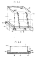
- Fig. 1 is a perspective view showing an external appearance of a toner container unit 1 in the state its opening portion is sealed by a film-like sheet
- Fig. 2 shows a sectional view (taken along II-II in Fig. 1) of the unit 1 in the same state.
- Such a unit is disclosed in older EP-application EP-83106359.9.
- the reference numeral 11 denotes a container body which has a tubular form opened at its at least one end, and which is formed of plastic, paper or the like.
- the numeral 12 denotes a fixed cover which may be formed as a plastic- molded product integrally with the container body 11.
- the reference numeral 13 denotes a base portion which is attached to an opening end of the container body 11. It is also possible that the container body 11 made of plastic and molded integrally with the base portion 13.
- the base portion 13 is provided with a pair of projected portions 131 (Fig. 3) on the left and right sides with respect to the sliding direction, the projected portions 131 being engaged with the sliding portions of a later-described slide cover 15.
- the reference numeral 14 denotes a film-like sheet for sealing an opening portion 132 of the base portion 13, which sheet is bonded by, for example, adhesives to a lower end surface 133 of the base portion 13 atthe periphery of the opening portion 132 in a separatable manner.
- the film-like sheet 14 has its front end 141 which is rigidly bonded to a front end fixing portion 1321 located near one end of the opening portion 132.
- the upper surface of the film-like sheet 14 is bonded to the lower end surface 133 in a separatable manner, and its extended portion is folded back at the seal end near the other end of the opening portion 132 so as to return passing the outer side of the slide cover 15.
- a rear end 142 of the film-like sheet 14 is rigidly bonded to a rear end fixing portion 1322 locating nearthefrontend fixing portion 1321 and constituting the upper surface thereof.
- the film-like sheet 14 may be formed of those materials, such as a polyester film, which are flexible and also has strength enough to resist against breakage.
- the slide cover 15 serves to protect the film-like sheet 14 adapted to seal the opening portion during storage or transportation, and to open the container as required, the slide cover being made of a metal, plastic, etc.
- the slide cover 15 is formed with a pair of slide grooves 151 to be engaged with the paired projected portions 131 of the base portion 13. As will be seen from the sectional view of Fig. 2, toner within the container body 11 is supported by both the film-like sheet 14 and the slide cover 15 during storage or transportation.
- the slide cover 15 may be provided with reinforcing crosspieces which extend in the sliding direction or the direction at a right angle with respect thereto, or which are arranged in the form of a lattice, as required.
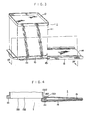
- Fig. 3 is a perspective view showing the toner container unit 1 at the time of resupplying toner
- Fig. 4 is sectional view (taken along IV-IV in Fig. 3) of the unit in such a state
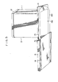
- Fig. 5 is a perspective view showing the external appearance thereof in the same state when viewed obliquelyfrom below.
- the film-like sheet 14 is also pulled together with the movement of the slide cover 15 and it is gradually torn off from the other end side of the lower end surface of the opening portion 132.
- the opening portion 132 comes into the mostly opened state, so thattonerT within the container body 11 may drop to be resupplied.
- the slide cover 15 When resupply of toner is completed, the slide cover 15 is slid back leftward. With this, the film-like sheet 14 having been torn off in the above process is also returned to the original position, i.e., restored to the state as shown in Fig. 1. Then, the toner container unit 1 is removed from a hopper of a reproducing apparatus which will be described later on.
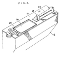
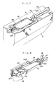
- FIG. 6 is a perspective view of the toner hopper
- Fig. 7 is a sectional view showing an essential part thereof
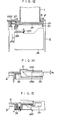
- Fig. 8 is a perspective view of an openable cover.
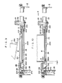
- Figs. 9, 10 and 11 are sectional views of the toner hopper 2, showing the different states;
- Fig. 9 is a sectional view showing the state where the toner container unit 1 is not yet mounted,
- Fig. 10 is a sectional view showing the state where the toner container unit 1 is just mounted, and
- Fig. 11 is a sectional view showing the state where, after mounting of the toner container unit 1, a later-described knob 25 is moved rightward on the figure to open both container unit and hopper.
- Fig. 12 is a sectional view taken along XII-XII in Fig. 11.
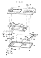
- Fig. 13 is an exploded perspective view which shows the mounting state of respective components of the toner hopper 2.
- the upper cover 21 and an intermediate cover 22 are integrally fastened to the upper surface of the toner hopper 2.
- the upper cover 21 is made of molded-plastic and formed with an opening 211.
- the intermediate cover 22 is also made of molded-plastic and formed with an opening 221 at a position corresponding to the opening 211 in the upper cover. Both openings 211 and 221 serve as an opening portion used for mounting of the toner container unit 1.
- the upper cover 21 includes an elongated hole 212 through which the knob 25 is moved.
- an openable cover 23 Interposed between the upper cover 21 and the intermediate cover 22 is an openable cover 23 slidable to open and close both openings 211 and 221.
- the openable cover 23 is also made of molded-plastic and has its one end to which is fixed a knob mounting plate 231.
- the leading end portion of the plate 231 extends upwards through the elongated hole 212 in the upper cover 21 up to above the upper cover 21, and the knob 25 is attached to the extended top end of the plate 231.
- the other end of the openable cover 23 forms an inclined surface projecting upwards, and a blade 232 made of an elastic thin plate according to this invention is mounted along the inclined surface.
- Neoprene rubber, urethane rubber, buthyl rubber, SBR rubber, NBR rubber, etc. in the shape of a sheet may be used as a material for the blade 232.
- a pair of compressed springs 233 which are in abutment with a rising portion 241 formed at one end of a slide plate 24 capable of sliding on the openable cover 23, thereby to push the slide plate 24 always leftward on the figures.
- the other end of the slide plate 24 is bent to form a U-shaped portion 242, and the openable cover 23 is held between the horizontal two parts of the U-shaped portion 242. Stated differently, the end portion of the openable cover 23 is surrounded by the U-shaped portion 242 of the slide plate 24, thereby providing a double structure comprising the openable cover 23 and the slide plate 24.
- a pushing-up spring A222 and a pairof pushing-up springs B 223 are attached onto the surface of the intermediate cover 22 to push the openable cover 23 upwards, so that the upper surface of the openable cover 23 comes into abutment with the rear (or lower) surface of the upper cover 21.
- An upper end of the blade 232 abuts with the sliding surface constituting the rear surface of the upper cover 21, thereby to remove the toner having adhered onto the sliding surface when the openable cover 23 is moved leftward for closing.
- a packing 224 formed of a sponge material is attached onto the upper surface of the intermediate cover 22 to prevent toner from entering a space between the intermediate cover 22 and the openable cover 23.
- a pair of stepped portions 2301 are formed on the upper surface of the openable cover 23 on both sides, while a pair of stepped portions 2101 are formed on the lower surface of the upper cover 21.
- the openable cover 23 is pushed up by means of both the pushing-up springs A 222 and B 223, so that the stepped portions 2301 are engaged with the stepped portions 2101.
- Fig. 15 shows the state where the pushing-up springs B 223 pushes the openable cover 23 upwards
- Fig. 14 shows the relationship between both stepped portions in engagement with each other.
- a lock mechanism is provided at the left end of the intermediate cover 22. More specifically, there is provided a compressed spring 234 to push a locking member 26 rightward, which is composed of a locking pawl member 261 and a locking base plate 262 coupled integrally to each other, and which is slidable leftward and rightward.
- the locking member 26 serves as a member for mounting and supporting the toner container unit 1, and it operates as a lock mechanism when the openable cover 23 is opened. But when the openable cover 23 is closed, a front end portion 2302 of the openable cover 23 prevents the locking member 26 from moving rightward, whereby the lock mechanism will not operate even with the toner container unit 1 being mounted.
- the openable cover 23 is provided with a projected portion 2303 protruding sidewards therefrom.
- the projected portion 2303 is engaged with a slide member 271 which is slidable in the intermediate cover 22 together with the movement of the openable cover 23.
- the slide member 271 is provided with a shaft 272 extending at a right angle with respect to the sliding direction thereof and locating at a position to the left of its opening 221, and with a stopper member 273.
- a leveling plate 28 is attached to the shaft 272 to be rotatable thereabout. The leveling plate 28 thus provided has a function to prevent toner from being filled into the hopper one-sidedly.
- the leveling plate 28 is so constructed that its rotation in the clockwise direction is stopped at the vertical position by virtue of the stopper member 273, while its rotation in the counterclockwise direction is allowed up to the horizontal position.
- the knob 25 is moved rightward to open the openable cover 23
- the leveling plate 28 is also moved rightward together with the openable cover 23 but behind opening thereof (Fig. 11). Therefore, the leveling plate 28 is moved rightward in the toner hopper 2 while keeping its vertical attitude with the aid of the stopper member 273.
- the toner container unit 1 is mounted to the left end of the hopper 2, so that toner is filled into the hopper 2 one-sidedly on the left side thereof. Accordingly, the toner hopper of this invention has such a construction that the toner dropped on the left side upon opening is pushed and shifted by the presence of the newly provided leveling plate 28 toward the right side where no toner drops thereinto.
- FIG. 9 there is illustrated a sectional view of the toner hopper 2 in the state before mounting of the toner container unit 1, both the openings 211 and 221 of the toner hopper 2 are closed with the openable cover 23.
- the openable cover 23 is pushed upward by means of the pushing-up springs A 222 and B 223 to make the upper surface of the openable cover 23 coming into close contact with the rear surface of the upper cover 21 at their peripheral edge portions, whereby the toner within the toner hopper 2 is surely prevented from leaking to the outside.
- the stepped portion 2101 provided on the rear surface of the upper cover 21 is engaged with the stepped portion 2301 provided on the upper surface of the openable cover 23, so that the knob 25 will not move rightward, even if so intended, because of the locked relationship therebetween.
- the openable cover 23 is brought into the locked state to surely hold both the openings 211 and 221 in the closed state, and it is prevented that the erroneous operation may lead to opening of the openable cover and may result in toner contamination in the surroundings of the hopper.
- the toner container unit 1 is inserted into the openings 211 of the toner hopper 2 along the direction indicated by an arrow S (Fig. 9) with the fixing portion 1321 (1322) being directed ahead.
- the rear end (right end on the figure) of the slide cover 15 of the toner container unit 1 is brought into abutment with the rising portion 241 of the slide plate 24, and from this state the toner container unit 1 is pressed downwards obliquely to be mounted in the opening 211 while compressing the compressed spring 233.
- Fig. 9 The toner container unit 1 is inserted into the openings 211 of the toner hopper 2 along the direction indicated by an arrow S (Fig. 9) with the fixing portion 1321 (1322) being directed ahead.
- the rear end (right end on the figure) of the slide cover 15 of the toner container unit 1 is brought into abutment with the rising portion 241 of the slide plate 24, and from this state the toner container unit 1 is pressed downwards obliquely to be mounted in the opening 211 while
- the slide plate 24 is shifted rightward by a distance of 1 1 , so that the front end of the openable cover (i.e., the front end 242 of the slide plate) is positioned to the right of the front end of the slide cover 15.
- toner is prevented from adhering onto the openable cover 23 at the time of its opening.
- the openable cover 23 which has been pushed up by means of both the pushing-up springs A 222 and B 223, is now sunk downward by a distance of 1 2 (Fig. 14), whereby the locked engagement between the stepped portions 2101 and 2301 is released.
- the knob 25 becomes movable rightward (i.e., in the direction indicated by an arrow R in Fig. 10).
- the locking member 26 which has been blocked from moving from the front end portion 2302 of the openable cover 23, is now also moved rightward by a released resilient force of the compressed spring 234, thereby to lock the toner container unit 1. Accordingly, the toner container unit 1 is locked up by the locking member 26 and hence can not be removed during opening of the toner container unit 1 and the openable cover 23.
- the slide cover 15 of the toner container unit 1 is opened and the seal of the film-like sheet 14 is torn off, so that the toner within the toner container unit 1 drops into the toner hopper 2.
- the leveling plate 28 starts to move.
- the leveling plate 28 is pushed by the toner into the vertical position where it comes into abutment with the stopper member 273.
- the leveling plate 28 held in the vertical attitude is moved rightward so as to sweep the inside of the toner hopper 2 and to carry the toner having been filled up relatively toward the right side, thereby leveling the toner within the toner hopper 2 to have a uniform level.
- the projection piece 281 of the leveling plate 28 strikes against the projected portion 2201 formed to protrude from the lower surface of the intermediate cover 22, so that the leveling plate 28 is made spring up in the counterclockwise direction, thereby to send the toner toward the right side with a strong force.
- the leveling plate 28 is made spring up in the counterclockwise direction, thereby to send the toner toward the right side with a strong force.
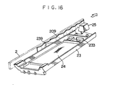
- Fig. 16 is a perspective view of an essential part showing one embodiment of this invention.
- a vibration generating section is disposed between the toner hopper 2 as a stationary part and the openable cover 23 as a slidable part.
- the toner hopper 2 is provided at its side surface with an uneven plate 209 formed of ⁇ -deformable leaf spring, while the openable cover 23 is provided with a projection 239 fixed to its side surface.
- the projection 239 of the openable cover 23 passes over the uneven plate 209 with jerks, thus generating vibrations. Therefore, since there generate vibrations when the openable cover 23 is moved rightward, even such toner in the solidified state within the toner container unit 1 under influence of moisture or so can be dropped into the toner hopper through the opening portions upon opening of the slide cover 15 due to the vibrations generated.
- the knob 25 is moved leftward (in the direction indicated by an arrow T in Fig. 11), so that the respective components are returned to the state as shown in Fig. 10.
- the blade 232 makes a slide contact with the sliding surface constituting the rear surface of the upper cover 21 to remove the toner which has adhered onto the sliding surface when dropped.
- the movement of the openable cover 23 is made smooth at all times.
- the leveling plate 28 When the openable cover 23 is moved leftward, the leveling plate 28 is turned from its vertical attitude in the counterclockwise direction about the shaft 272, as shown by chain lines in Fig. 11, so that it returns sliding over the toner surface without moving the toner leftward.
- the slide cover 15 In conjunction with closing of the openable cover 23, the slide cover 15 is also closed and the film-like sheet 14 is returned from its torn off state to the original state. At the time of closing, the openable cover 23 of the toner hopper 2 is closed behind the slide cover 15 by a distance of 1 1 , whereby the cover member of the toner hopper 2 is not contaminated with toner, even if some toner drops late.
- the locking member 26 which engaged with and locked the base portion 13 of the toner container unit 1 is now pushed to retreat leftward, thereby to release the locked engagement therebetween.
- the openable cover 23 is pushed upward by means of both the pushing-up springs A 222 and B 223 by a distance of 1 2 , so that the stepped portions 2301 and 2101 are engaged into the locked state where the knob 25 will not move, thereby to surely inhibit the opening operation.
- toner dispensing apparatus it becomes possible to prevent toner from escaping or scattering to the outside as well as toner contamination in the surroundings of the hopper caused by possible erroneous operation, at the time of supplying toner with the toner container unit being mounted on the toner hopper.
- the safety lock mechanism is provided to eliminate such a possibility that the toner container unit 1 is erroneously removed during opening of the openable cover. As a result, the surroundings of the apparatus is positively protected from toner contamination due to erroneous operation.
- the toner container unit can be mounted in position without causing toner contamination in the outside.
- Toner resupplied into the apparatus is not filled up one-sidedly, but distributed uniformly, thereby assuring superior development with no unevenness.
- toner container unit With the toner container unit being mounted, it is possible to surely resupply toner without causing a fear of toner contamination in the surroundings.
Landscapes
- Physics & Mathematics (AREA)
- General Physics & Mathematics (AREA)
- Dry Development In Electrophotography (AREA)
Description
- This invention relates to an improvement of a toner dispensing apparatus for receiving toner from a toner container unit prepared separately in an electrostatic reproducing apparatus which uses a dry developer.
- In an electrostatic reproducing apparatus using a dry two-component developer or one-component toner, toner is consumed in the process of reproduction and it becomes required to resupply toner after many copies have been reproduced. Resupply of toner is made usually by filling up toner into a toner hopper of the electrostatic reproducing apparatus from a toner container unit which houses therein toner. Toner is in the form of powder which has an average particle size of several tens pm, and hence is liable to scatter. Therefore, when toner is resupplied with the toner container unit being mounted to a toner inlet opening of the hopper, it happens very often that toner escapes or scatters to the outside and this causes contamination in the surroundings. It has been also experienced oftenly that there occurs toner contamination due to possible erroneous operation at the time of mounting the toner container unit or during other necessary operations.
- From this reason, there has been proposed such a construction that a toner container unit closed by a cover is mounted on a toner hopper closed by a cover, and then the slide cover of the toner container unit and the openable cover of the toner hopper are opened at the same time. However, when both the slide cover and the openable cover are opened at the same time, toner starts to drop upon opening of the slide cover, so that the upper surface of the leading end portion, of the openable cover is contaminated with toner each time. It was thus unavoidable that the opening portion of the toner hopper is subject to toner contamination, at the time when the toner container unit is removed after resupply of toner.
- Further, if the toner container unit should be removed erroneously during resupply of toner, toner may scatter into the surroundings of the apparatus, thereby resulting in the uncontrollable state oftentimes.
- In addition, the toner hopper has encountered the following problem to be solved. Since the hopper resupplied with toner from the toner container unit has to feed toner uniformly all over the width of recording paper, it has a length corresponding to the width of recording paper in usual cases. On the other hand, the opening portion of the toner container unit has a relatively small length, so that toner is filled into the hopper one-sidedly, if the toner container unit is mounted on the hopper and then opened to allow the toner just to drop from the toner container unit into the hopper. Development in this state may result in such a disadvantage that the toner is not agitated sufficiently in the development section and there occurs variations in darkness of the copy in the widthwise direction, whereby the desired uniform development is not secured.
- Further, in case toner in the toner container unit has been solidified due to moisture or so, the toner will remain in the toner container unit and will not drop into the hopper, even when the slide cover of the toner container unit and the openable cover of the hopper are opened together. In this case, therefore, resupply of toner is not attained to the desired extent very often.
- Moreover, in a toner hopper having a cover which is slidable to be opened and closed, toner tends to adhere on the sliding surface and the cover suffers greater resistance in its sliding movement. And it becomes difficult to open and close the cover in not a few cases.
- Document US-A-3 385 500 discloses a toner package having a rectangular body and a separable bottom wall formed of a strip being integral with the body and including a tab portion partially integral with one of the ends for attachment to a stripping mechanism for releasing the toner held in the package and for separating the bottom wall from the body. The apparatus using this toner package comprises a container having an openable cover and a seal member.
- It is an object of the present invention to provide a toner dispensing apparatus which prevents toner contamination in the surroundings of a toner container unit that may be caused by possible careless operation.
- To achieve this object, the present invention provides a toner dispensing apparatus comprising a toner receiving portion having an openable cover for opening and closing an opening portion of the toner receiving portion, and a toner container unit having a container, a seal member for sealing an opening portion of the container, and means for fitting said container unit with the toner receiving portion so that both opening portions are superposed, said toner dispensing apparatus being characterized in that the container unit comprises a slide member connected with a portion of said seal member and slidable with respect to said opening portion of the container, said seal member being torn off from said opening portion of the container when said slide member is moved in conjunction with the opening motion of said openable cover.
- In a preferred embodiment, the toner dispensing apparatus is characterized in that said openable cover in the closed state is released from a locked state when the toner container unit is mounted against the force of a retaining spring member.
- In a further preferred embodiment, the toner dispensing apparatus is characterized in that a locking member is provided which prevents removal of the toner container unit during the opened state of the openable cover.
- A further preferred embodiment of the present invention which enables a toner dispensing apparatus having an openable cover which is able to slide to open and close its opening portion is characterized in that a leveling plate is provided which moves together with said openable cover after opening of said openable cover.
- Another preferred embodiment of the invention in which the cover of the toner dispensing apparatus is opened together with a cover of the toner container unit is characterized in that a slide plate is provided on the openable cover, operable by a spring which is compressed to slide said slide plate on said openable cover when the toner container unit is mounted on the opening portion of said apparatus.
- In a further embodiment, the toner dispensing apparatus which permits toner within the toner container unit mounted thereon to drop into the apparatus without failure is characterized in that said openable cover and/or the sliding portion on its sliding surface are formed unevenly, whereby said openable cover is moved with adequate vibrations. In other words, the toner container unit is subjected to vibrations in conjunction with opening and closing of the covers of both toner container unit and toner dispensing apparatus, so that toner is dropped to fill up the dispensing apparatus correctly.
- Another embodiment of the invention, in which the cover of the toner dispensing apparatus is able to slide to open and close its opening portion is characterized in that a blade is provided on said openable cover to remove the toner adhered on the sliding surface of said openable cover, at the time when said openable cover is closed.
- Thus, to prevent toner contamination in the surroundings of a toner dispensing apparatus that may be caused by possible careless operation, and to supply toner within a toner container unit into the apparatus assuredly without causing such contamination in the surroundings, the toner dispensing apparatus has an openable cover adapted to open and close its opening portion, and a toner container unit having at its opening portion a slide cover and a seal member, the latter being torn off in conjunction with the slide cover, is mounted on the opening portion of the toner dispensing apparatus, and both the slide cover and the seal member are opened and closed together with the openable cover of the apparatus.
- Other objects and features of this invention will be apparent from the following description given with reference to the drawings.
- Figs. 1,3 and 5 are perspective views showing an external appearance of a toner container unit;
- Figs. 2 and 4 are sectional views thereof;
- Fig. 6 is a perspective view of a toner dispensing apparatus according to this invention;
- Fig. 7 is a sectional view showing an essential part thereof;
- Fig. 8 is a perspective view of an openable cover;
- Figs. 9, 10, and 11 are sectional views showing three different states of the toner dispensing apparatus, respectively;
- Fig. 12 is a sectional view taken along the line XII-XII in Fig. 11;
- Fig. 13 is an exploded perspective view;
- Fig. 14 is an explanatory view showing the engaged state of stepped portions;
- Fig. 15 is a sectional view of an essential part showing the relationship between a pushing-up spring and the openable cover; and
- Fig. 16 is a perspective view of an essential part showing the sliding section according to one embodiment of this invention.
- The construction of a toner container unit is first described and then there will be described the construction and operation of a toner dispensing apparatus according to this invention, which apparatus is resupplied with toner from the toner container unit mounted thereon.
- Fig. 1 is a perspective view showing an external appearance of a toner container unit 1 in the state its opening portion is sealed by a film-like sheet, and Fig. 2 shows a sectional view (taken along II-II in Fig. 1) of the unit 1 in the same state. Such a unit is disclosed in older EP-application EP-83106359.9.
- In the figures, the reference numeral 11 denotes a container body which has a tubular form opened at its at least one end, and which is formed of plastic, paper or the like. The
numeral 12 denotes a fixed cover which may be formed as a plastic- molded product integrally with the container body 11. - The
reference numeral 13 denotes a base portion which is attached to an opening end of the container body 11. It is also possible that the container body 11 made of plastic and molded integrally with thebase portion 13. Thebase portion 13 is provided with a pair of projected portions 131 (Fig. 3) on the left and right sides with respect to the sliding direction, the projectedportions 131 being engaged with the sliding portions of a later-describedslide cover 15. - The
reference numeral 14 denotes a film-like sheet for sealing anopening portion 132 of thebase portion 13, which sheet is bonded by, for example, adhesives to alower end surface 133 of thebase portion 13 atthe periphery of theopening portion 132 in a separatable manner. The film-like sheet 14 has itsfront end 141 which is rigidly bonded to a frontend fixing portion 1321 located near one end of theopening portion 132. The upper surface of the film-like sheet 14 is bonded to thelower end surface 133 in a separatable manner, and its extended portion is folded back at the seal end near the other end of theopening portion 132 so as to return passing the outer side of theslide cover 15. And arear end 142 of the film-like sheet 14 is rigidly bonded to a rearend fixing portion 1322 locatingnearthefrontend fixing portion 1321 and constituting the upper surface thereof. The film-like sheet 14 may be formed of those materials, such as a polyester film, which are flexible and also has strength enough to resist against breakage. - The
slide cover 15 serves to protect the film-like sheet 14 adapted to seal the opening portion during storage or transportation, and to open the container as required, the slide cover being made of a metal, plastic, etc. Theslide cover 15 is formed with a pair ofslide grooves 151 to be engaged with the paired projectedportions 131 of thebase portion 13. As will be seen from the sectional view of Fig. 2, toner within the container body 11 is supported by both the film-like sheet 14 and theslide cover 15 during storage or transportation. - Incidentally, the
slide cover 15 may be provided with reinforcing crosspieces which extend in the sliding direction or the direction at a right angle with respect thereto, or which are arranged in the form of a lattice, as required. - Fig. 3 is a perspective view showing the toner container unit 1 at the time of resupplying toner, Fig. 4 is sectional view (taken along IV-IV in Fig. 3) of the unit in such a state, and Fig. 5 is a perspective view showing the external appearance thereof in the same state when viewed obliquelyfrom below.
- When the
slide cover 15 is drawn out toward the fixing portion 1321 (1322) (in the rightward direction on the figures), the film-like sheet 14 is also pulled together with the movement of theslide cover 15 and it is gradually torn off from the other end side of the lower end surface of theopening portion 132. In the state where theslide cover 15 is fully drawn out rightward, theopening portion 132 comes into the mostly opened state, so thattonerT within the container body 11 may drop to be resupplied. - When resupply of toner is completed, the
slide cover 15 is slid back leftward. With this, the film-like sheet 14 having been torn off in the above process is also returned to the original position, i.e., restored to the state as shown in Fig. 1. Then, the toner container unit 1 is removed from a hopper of a reproducing apparatus which will be described later on. - Hereinafter there will be described a
toner hopper 2 according to this invention. Fig. 6 is a perspective view of the toner hopper, Fig. 7 is a sectional view showing an essential part thereof, and Fig. 8 is a perspective view of an openable cover. Figs. 9, 10 and 11 are sectional views of thetoner hopper 2, showing the different states; Fig. 9 is a sectional view showing the state where the toner container unit 1 is not yet mounted, Fig. 10 is a sectional view showing the state where the toner container unit 1 is just mounted, and Fig. 11 is a sectional view showing the state where, after mounting of the toner container unit 1, a later-describedknob 25 is moved rightward on the figure to open both container unit and hopper. Fig. 12 is a sectional view taken along XII-XII in Fig. 11. And Fig. 13 is an exploded perspective view which shows the mounting state of respective components of thetoner hopper 2. - First, the construction of the
toner hopper 2 according to this invention will be described by mainly referring to Fig. 13. Anupper cover 21 and anintermediate cover 22 are integrally fastened to the upper surface of thetoner hopper 2. Theupper cover 21 is made of molded-plastic and formed with anopening 211. Theintermediate cover 22 is also made of molded-plastic and formed with anopening 221 at a position corresponding to theopening 211 in the upper cover. Bothopenings upper cover 21 includes anelongated hole 212 through which theknob 25 is moved. - Interposed between the
upper cover 21 and theintermediate cover 22 is anopenable cover 23 slidable to open and close bothopenings openable cover 23 is also made of molded-plastic and has its one end to which is fixed aknob mounting plate 231. The leading end portion of theplate 231 extends upwards through theelongated hole 212 in theupper cover 21 up to above theupper cover 21, and theknob 25 is attached to the extended top end of theplate 231. The other end of theopenable cover 23 forms an inclined surface projecting upwards, and ablade 232 made of an elastic thin plate according to this invention is mounted along the inclined surface. Neoprene rubber, urethane rubber, buthyl rubber, SBR rubber, NBR rubber, etc. in the shape of a sheet may be used as a material for theblade 232. - At the right end of the
openable cover 23 are provided a pair ofcompressed springs 233, which are in abutment with a risingportion 241 formed at one end of aslide plate 24 capable of sliding on theopenable cover 23, thereby to push theslide plate 24 always leftward on the figures. The other end of theslide plate 24 is bent to form aU-shaped portion 242, and theopenable cover 23 is held between the horizontal two parts of theU-shaped portion 242. Stated differently, the end portion of theopenable cover 23 is surrounded by theU-shaped portion 242 of theslide plate 24, thereby providing a double structure comprising theopenable cover 23 and theslide plate 24. - A pushing-up spring A222 and a pairof pushing-up
springs B 223 are attached onto the surface of theintermediate cover 22 to push theopenable cover 23 upwards, so that the upper surface of theopenable cover 23 comes into abutment with the rear (or lower) surface of theupper cover 21. An upper end of theblade 232 abuts with the sliding surface constituting the rear surface of theupper cover 21, thereby to remove the toner having adhered onto the sliding surface when theopenable cover 23 is moved leftward for closing. A packing 224 formed of a sponge material is attached onto the upper surface of theintermediate cover 22 to prevent toner from entering a space between theintermediate cover 22 and theopenable cover 23. - A pair of stepped
portions 2301 are formed on the upper surface of theopenable cover 23 on both sides, while a pair of steppedportions 2101 are formed on the lower surface of theupper cover 21. In the closed state (Fig. 9), theopenable cover 23 is pushed up by means of both the pushing-up springs A 222 andB 223, so that the steppedportions 2301 are engaged with the steppedportions 2101. Fig. 15 shows the state where the pushing-upsprings B 223 pushes theopenable cover 23 upwards, and Fig. 14 shows the relationship between both stepped portions in engagement with each other. - Furthermore, a lock mechanism is provided at the left end of the
intermediate cover 22. More specifically, there is provided acompressed spring 234 to push a lockingmember 26 rightward, which is composed of a lockingpawl member 261 and a lockingbase plate 262 coupled integrally to each other, and which is slidable leftward and rightward. The lockingmember 26 serves as a member for mounting and supporting the toner container unit 1, and it operates as a lock mechanism when theopenable cover 23 is opened. But when theopenable cover 23 is closed, afront end portion 2302 of theopenable cover 23 prevents the lockingmember 26 from moving rightward, whereby the lock mechanism will not operate even with the toner container unit 1 being mounted. - The
openable cover 23 is provided with a projectedportion 2303 protruding sidewards therefrom. The projectedportion 2303 is engaged with aslide member 271 which is slidable in theintermediate cover 22 together with the movement of theopenable cover 23. Theslide member 271 is provided with ashaft 272 extending at a right angle with respect to the sliding direction thereof and locating at a position to the left of itsopening 221, and with astopper member 273. A levelingplate 28 is attached to theshaft 272 to be rotatable thereabout. The levelingplate 28 thus provided has a function to prevent toner from being filled into the hopper one-sidedly. The levelingplate 28 is so constructed that its rotation in the clockwise direction is stopped at the vertical position by virtue of thestopper member 273, while its rotation in the counterclockwise direction is allowed up to the horizontal position. When theknob 25 is moved rightward to open theopenable cover 23, the levelingplate 28 is also moved rightward together with theopenable cover 23 but behind opening thereof (Fig. 11). Therefore, the levelingplate 28 is moved rightward in thetoner hopper 2 while keeping its vertical attitude with the aid of thestopper member 273. In this embodiment, the toner container unit 1 is mounted to the left end of thehopper 2, so that toner is filled into thehopper 2 one-sidedly on the left side thereof. Accordingly, the toner hopper of this invention has such a construction that the toner dropped on the left side upon opening is pushed and shifted by the presence of the newly provided levelingplate 28 toward the right side where no toner drops thereinto. - In the final stroke of the rightward movement of the leveling
plate 28, aprojection piece 281 formed by a part of the levelingplate 28 and protruding up to above theshaft 272 strikes against a projectedportion 2201 provided to protrude from the lower surface of theintermediate cover 22. With this, the levelingplate 28 is turned about the.shaft 272 from its vertical attitude up to a position near the horizontal level, thereby allowing toner to spring up. This arrangement has been designed with a view of adding the action to push toner at the final position of the stroke in order to shift the toner further toward the right side, taking into account the fact that only the parallel movement of the levelingplate 28 together with the opening motion of the openable cover can not provide the sufficient effect. - Hereinafter operation of the
toner hopper 2 as mentioned above will be described in relation to the mounting operation of the toner container unit 1. - Referring to Fig. 9 there is illustrated a sectional view of the
toner hopper 2 in the state before mounting of the toner container unit 1, both theopenings toner hopper 2 are closed with theopenable cover 23. In this state, theopenable cover 23 is pushed upward by means of the pushing-up springs A 222 andB 223 to make the upper surface of theopenable cover 23 coming into close contact with the rear surface of theupper cover 21 at their peripheral edge portions, whereby the toner within thetoner hopper 2 is surely prevented from leaking to the outside. At the same time, the steppedportion 2101 provided on the rear surface of theupper cover 21 is engaged with the steppedportion 2301 provided on the upper surface of theopenable cover 23, so that theknob 25 will not move rightward, even if so intended, because of the locked relationship therebetween. In other words, theopenable cover 23 is brought into the locked state to surely hold both theopenings - The toner container unit 1 is inserted into the
openings 211 of thetoner hopper 2 along the direction indicated by an arrow S (Fig. 9) with the fixing portion 1321 (1322) being directed ahead. The rear end (right end on the figure) of theslide cover 15 of the toner container unit 1 is brought into abutment with the risingportion 241 of theslide plate 24, and from this state the toner container unit 1 is pressed downwards obliquely to be mounted in theopening 211 while compressing thecompressed spring 233. In the state as shown in Fig. 10, theslide plate 24 is shifted rightward by a distance of 11, so that the front end of the openable cover (i.e., thefront end 242 of the slide plate) is positioned to the right of the front end of theslide cover 15. With this arrangement, toner is prevented from adhering onto theopenable cover 23 at the time of its opening. - Moreover, upon mounting of the toner container unit 1, the
openable cover 23 which has been pushed up by means of both the pushing-up springs A 222 andB 223, is now sunk downward by a distance of 12 (Fig. 14), whereby the locked engagement between the steppedportions knob 25 becomes movable rightward (i.e., in the direction indicated by an arrow R in Fig. 10). - Subsequently, since a stepped
portion 2304 of theopenable cover 23 is now engaged with the front end of theslide cover 15 of the toner container unit 1, with theknob 25 being pulled rightward, theslide cover 15 is also moved rightward together with theopenable cover 23 while tearing off the film-like sheet 14 which has been bonded to the lower end surface of theopening portion 132, whereby both the toner container unit 1 and thetoner hopper 2 are opened at the same time. - When the
openable cover 23 is moved rightward, the lockingmember 26 which has been blocked from moving from thefront end portion 2302 of theopenable cover 23, is now also moved rightward by a released resilient force of thecompressed spring 234, thereby to lock the toner container unit 1. Accordingly, the toner container unit 1 is locked up by the lockingmember 26 and hence can not be removed during opening of the toner container unit 1 and theopenable cover 23. - In this way, upon the rightward movement of the
openable cover 23, theslide cover 15 of the toner container unit 1 is opened and the seal of the film-like sheet 14 is torn off, so that the toner within the toner container unit 1 drops into thetoner hopper 2. Behind dropping of the toner, the levelingplate 28 starts to move. At this time, the levelingplate 28 is pushed by the toner into the vertical position where it comes into abutment with thestopper member 273. Then, the levelingplate 28 held in the vertical attitude is moved rightward so as to sweep the inside of thetoner hopper 2 and to carry the toner having been filled up relatively toward the right side, thereby leveling the toner within thetoner hopper 2 to have a uniform level. In the final stroke, theprojection piece 281 of the levelingplate 28 strikes against the projectedportion 2201 formed to protrude from the lower surface of theintermediate cover 22, so that the levelingplate 28 is made spring up in the counterclockwise direction, thereby to send the toner toward the right side with a strong force. In such a manner, it becomes possible to evenly distribute the toner over all the area in thehopper 2 and hence to carry out superior development with no ununiformity in darkness of the copy. - According to an embodiment of this invention, in order to surely drop the toner within the toner container unit 1 into the
toner hopper 2 during the opening process of bothopenable cover 23 and slide cover 15 by the use of the toner hopper mounting the toner container unit, unevenness is formed on the sliding portion such as the side surface or rear surface of theopenable cover 23 and/or theupper cover 21 in slide contact therewith, so that theopenable cover 23 is moved passing over such unevenness. Fig. 16 is a perspective view of an essential part showing one embodiment of this invention. In this embodiment, a vibration generating section is disposed between thetoner hopper 2 as a stationary part and theopenable cover 23 as a slidable part. More specifically, thetoner hopper 2 is provided at its side surface with anuneven plate 209 formed of α-deformable leaf spring, while theopenable cover 23 is provided with aprojection 239 fixed to its side surface. With this arrangement, when theopenable cover 23 is moved to be opened or closed, theprojection 239 of theopenable cover 23 passes over theuneven plate 209 with jerks, thus generating vibrations. Therefore, since there generate vibrations when theopenable cover 23 is moved rightward, even such toner in the solidified state within the toner container unit 1 under influence of moisture or so can be dropped into the toner hopper through the opening portions upon opening of theslide cover 15 due to the vibrations generated. - After the completion of toner resupply, the
knob 25 is moved leftward (in the direction indicated by an arrow T in Fig. 11), so that the respective components are returned to the state as shown in Fig. 10. During this return movement, theblade 232 makes a slide contact with the sliding surface constituting the rear surface of theupper cover 21 to remove the toner which has adhered onto the sliding surface when dropped. As a result, the movement of theopenable cover 23 is made smooth at all times. - When the
openable cover 23 is moved leftward, the levelingplate 28 is turned from its vertical attitude in the counterclockwise direction about theshaft 272, as shown by chain lines in Fig. 11, so that it returns sliding over the toner surface without moving the toner leftward. - In conjunction with closing of the
openable cover 23, theslide cover 15 is also closed and the film-like sheet 14 is returned from its torn off state to the original state. At the time of closing, theopenable cover 23 of thetoner hopper 2 is closed behind theslide cover 15 by a distance of 11, whereby the cover member of thetoner hopper 2 is not contaminated with toner, even if some toner drops late. - Further, upon closing of the
openable cover 23, the lockingmember 26 which engaged with and locked thebase portion 13 of the toner container unit 1 is now pushed to retreat leftward, thereby to release the locked engagement therebetween. With the toner container unit 1 being removed from theopening 211, theopenable cover 23 is pushed upward by means of both the pushing-up springs A 222 andB 223 by a distance of 12, so that the steppedportions knob 25 will not move, thereby to surely inhibit the opening operation. - According to the above-mentioned toner dispensing apparatus it becomes possible to prevent toner from escaping or scattering to the outside as well as toner contamination in the surroundings of the hopper caused by possible erroneous operation, at the time of supplying toner with the toner container unit being mounted on the toner hopper.
- It becomes also possible to prevent toner contamination at the opening portion of the toner dispensing apparatus. Such contamination could not be avoided in the prior art.
- Further, the safety lock mechanism is provided to eliminate such a possibility that the toner container unit 1 is erroneously removed during opening of the openable cover. As a result, the surroundings of the apparatus is positively protected from toner contamination due to erroneous operation.
- Moreover, according to the toner dispensing apparatus of this invention, the toner container unit can be mounted in position without causing toner contamination in the outside.
- Toner resupplied into the apparatus is not filled up one-sidedly, but distributed uniformly, thereby assuring superior development with no unevenness.
- In addition to positive prevention of escaping or scattering of toner to the outside, it is secured that the toner within the toner container unit can be dropped without failure when the apparatus and the container unit are opened by moving the knob.
- With the toner container unit being mounted, it is possible to surely resupply toner without causing a fear of toner contamination in the surroundings.
- Furthermore, it becomes also possible to smoothly open and close the openable cover for a long term with no trouble.
Claims (11)
Applications Claiming Priority (16)
| Application Number | Priority Date | Filing Date | Title |
|---|---|---|---|
| JP57146445A JPS5936269A (en) | 1982-08-23 | 1982-08-23 | Toner receiving device |
| JP146446/82 | 1982-08-23 | ||
| JP146439/82 | 1982-08-23 | ||
| JP146445/82 | 1982-08-23 | ||
| JP57146439A JPS5934564A (en) | 1982-08-23 | 1982-08-23 | Toner receiving device |
| JP57146446A JPS5936270A (en) | 1982-08-23 | 1982-08-23 | Toner receiving device |
| JP146441/82 | 1982-08-23 | ||
| JP57146443A JPS5934568A (en) | 1982-08-23 | 1982-08-23 | Toner receiving device |
| JP57146444A JPS5936268A (en) | 1982-08-23 | 1982-08-23 | Toner receiving device |
| JP146443/82 | 1982-08-23 | ||
| JP57146441A JPS5934566A (en) | 1982-08-23 | 1982-08-23 | Toner receiving device |
| JP57146440A JPS5934565A (en) | 1982-08-23 | 1982-08-23 | Toner receiving device |
| JP57146442A JPS5934567A (en) | 1982-08-23 | 1982-08-23 | Toner receiving device |
| JP146442/82 | 1982-08-23 | ||
| JP146444/82 | 1982-08-23 | ||
| JP146440/82 | 1982-08-23 |
Publications (3)
| Publication Number | Publication Date |
|---|---|
| EP0102002A2 EP0102002A2 (en) | 1984-03-07 |
| EP0102002A3 EP0102002A3 (en) | 1984-07-25 |
| EP0102002B1 true EP0102002B1 (en) | 1987-11-04 |
Family
ID=27573198
Family Applications (1)
| Application Number | Title | Priority Date | Filing Date |
|---|---|---|---|
| EP83107900A Expired EP0102002B1 (en) | 1982-08-23 | 1983-08-10 | Toner dispensing apparatus |
Country Status (3)
| Country | Link |
|---|---|
| US (1) | US4491161A (en) |
| EP (1) | EP0102002B1 (en) |
| DE (1) | DE3374352D1 (en) |
Families Citing this family (60)
| Publication number | Priority date | Publication date | Assignee | Title |
|---|---|---|---|---|
| US4607938A (en) * | 1983-04-26 | 1986-08-26 | Canon Kabushiki Kaisha | Method and apparatus for forming a thin layer of developer |
| US4660958A (en) * | 1983-05-10 | 1987-04-28 | Canon Kabushiki Kaisha | Developing apparatus |
| DE3434563A1 (en) * | 1983-09-22 | 1985-04-11 | Ricoh Co., Ltd., Tokio/Tokyo | DEVELOPMENT DEVICE |
| US4615608A (en) * | 1983-10-31 | 1986-10-07 | Canon Kabushiki Kaisha | Developing apparatus |
| US4650097A (en) * | 1983-12-27 | 1987-03-17 | Sharp Kabushiki Kaisha | Developer material supply arrangement |
| US4639116A (en) * | 1985-04-02 | 1987-01-27 | Kentek Information Systems, Inc. | Printer/copier with disposable toner cartridge |
| US4969557A (en) * | 1985-11-26 | 1990-11-13 | Ricoh Co., Ltd. | Toner cartridge |
| GB8530466D0 (en) * | 1985-12-11 | 1986-01-22 | Xerox Corp | Dispensing cartridge |
| CN1003659B (en) * | 1986-02-06 | 1989-03-22 | 株式会社东芝 | Detergent supply device for washing machine etc. |
| US4778086A (en) * | 1986-02-27 | 1988-10-18 | Mita Industrial Co., Ltd. | Toner replenishing device |
| US4868599A (en) * | 1986-06-02 | 1989-09-19 | Seiko Epson Corporation | Device and method for storing toner waste |
| USRE34344E (en) * | 1986-11-28 | 1993-08-17 | Mita Industrial Co., Ltd. | Developing device |
| US4752807A (en) * | 1986-12-22 | 1988-06-21 | Eastman Kodak Company | Apparatus for adding toner to an electrographic development station |
| US4732277A (en) * | 1987-01-20 | 1988-03-22 | Xerox Corporation | Toner cartridge with removable sleeve closure |
| US4870463A (en) * | 1987-03-02 | 1989-09-26 | Mita Industrial Co., Ltd. | Latent electrostatic image developing device and toner cartridge |
| USD310845S (en) | 1987-07-02 | 1990-09-25 | Mita Industrial Co., Ltd. | Toner cartridge |
| USD310844S (en) | 1987-07-02 | 1990-09-25 | Mita Industrial Co., Ltd. | Toner cartridge |
| US4816877A (en) * | 1988-02-25 | 1989-03-28 | Fred Keen | Refillable toner cartridge and method of manufacture thereof |
| US4974023A (en) * | 1988-06-23 | 1990-11-27 | Sharp Kabushiki Kaisha | Developing device for copier |
| JPH0738089B2 (en) * | 1988-11-30 | 1995-04-26 | 三田工業株式会社 | Developer container |
| FR2643354B1 (en) * | 1989-02-21 | 1991-06-07 | Gallay Sa | TRANSFER INSTALLATION BETWEEN GRAVITY FLOWING CONTAINERS |
| US4937628A (en) * | 1989-04-07 | 1990-06-26 | Xerox Corporation | Apparatus for storing and dispensing particulate material |
| JPH02134554U (en) * | 1989-04-12 | 1990-11-08 | ||
| US4997016A (en) * | 1989-06-02 | 1991-03-05 | Eastman Kodak Company | Receiving apparatus for a toner container and toner container therefor |
| WO1990015366A1 (en) * | 1989-06-02 | 1990-12-13 | Eastman Kodak Company | Container for particulate material |
| USD321204S (en) | 1989-12-21 | 1991-10-29 | Texas Instruments Incorporated | Replaceable developer unit |
| US5235390A (en) * | 1990-03-20 | 1993-08-10 | Kabushiki Kaisha Toshiba | Developing device with toner cartridge cover shaped to prevent leakage |
| US5268722A (en) * | 1990-04-13 | 1993-12-07 | Canon Kabushiki Kaisha | Detachable developer supply container having means for selectively prohibiting detachment |
| US5080745A (en) * | 1990-05-29 | 1992-01-14 | Leslie Paull | Toner bin seal and sealing method |
| US5249020A (en) * | 1990-06-27 | 1993-09-28 | Asahi Kogaku Kogyo Kabushiki Kaisha | Developing device for electrophotographic image recording apparatus |
| JP2678084B2 (en) * | 1990-08-31 | 1997-11-17 | シャープ株式会社 | Developing device and developer cartridge used therein |
| US5142335A (en) * | 1990-11-26 | 1992-08-25 | Mita Industrial Co., Ltd. | Electrostatic latent image-developing device and toner cartridge used therefor |
| CA2068358C (en) * | 1991-05-14 | 1998-12-22 | Yoshihiko Yamada | Developer replenishing cartridge and developer receiving apparatus within which such cartridge is mounted |
| JP2934051B2 (en) * | 1991-05-29 | 1999-08-16 | 三田工業株式会社 | Toner replenishing method and toner cartridge used therefor |
| US5150807A (en) * | 1991-09-04 | 1992-09-29 | Xerox Corporation | Apparatus for storing marking particles |
| US5475479A (en) * | 1991-11-08 | 1995-12-12 | Canon Kabushiki Kaisha | Developer cartridge having an automatic lid closing mechanism |
| JP2907625B2 (en) * | 1992-02-03 | 1999-06-21 | キヤノン株式会社 | Developer supply container |
| JP3165729B2 (en) * | 1992-03-23 | 2001-05-14 | キヤノン株式会社 | Developing device and process cartridge |
| US5207353A (en) * | 1992-06-08 | 1993-05-04 | Eastman Kodak Company | Methods of and apparatus for replenishing toner in electrostatographic development stations |
| US5221945A (en) * | 1992-08-14 | 1993-06-22 | Xerox Corporation | Toner cartridge having an air passageway |
| SG67919A1 (en) * | 1993-06-25 | 1999-10-19 | Canon Kk | Developing apparatus process cartridge and image forming apparatus |
| DE69410571T2 (en) * | 1993-11-01 | 1998-11-19 | Canon Kk | Process unit and imaging device |
| US5523828A (en) * | 1994-09-14 | 1996-06-04 | De Kesel; Jan | Seal for a toner cartridge assembly |
| US5878306A (en) * | 1997-07-18 | 1999-03-02 | Michlin; Steven Bruce | Disposable strip holder installation device and method used in the imaging and other industries |
| US6356724B1 (en) * | 1995-01-10 | 2002-03-12 | Steven Bruce Michlin | Disposable strip holder installation device and placement holding device and method for copiers, laser printers, fax machines and for toner cartridges used therein |
| JPH08272282A (en) * | 1995-04-03 | 1996-10-18 | Canon Inc | Image forming apparatus, process cartridge and toner hopper |
| JP3507222B2 (en) * | 1995-10-26 | 2004-03-15 | キヤノン株式会社 | Toner supply container |
| JP3471992B2 (en) * | 1995-10-26 | 2003-12-02 | キヤノン株式会社 | Toner supply container and image forming apparatus |
| FR2748331B1 (en) * | 1996-05-02 | 1998-06-12 | Sagem | SET OF TWO CONTAINERS FOR COMMUNICATING BETWEEN THEM FOR THE LOADING OF EACH OTHER WITH A CONSUMABLE PRODUCT |
| US5819144A (en) * | 1996-06-28 | 1998-10-06 | Mita Industrial Co., Ltd. | Toner replenishing device of image forming machine |
| IT1284596B1 (en) * | 1996-09-27 | 1998-05-21 | Luigi Goglio | CONTAINER OF GRANULAR PRODUCTS IN PARTICULAR COFFEE AND RELATIVE SUPPORT FOR EMPTYING IN A BAR MILL |
| DK1028068T3 (en) * | 1999-02-12 | 2003-06-02 | Nestle Sa | Spare cartridge for beverage distribution device adapted to such a cartridge |
| JP2000284582A (en) * | 1999-03-31 | 2000-10-13 | Sharp Corp | Developer cartridge |
| US6314262B1 (en) * | 1999-07-23 | 2001-11-06 | Sharp Kabushiki Kaisha | Toner supply system and toner cartridge |
| EP1176477A1 (en) * | 2000-07-24 | 2002-01-30 | Océ-Technologies B.V. | Refill mechanism for toner powder |
| ES2215565T3 (en) * | 2000-09-15 | 2004-10-16 | Societe Des Produits Nestle S.A. | ELEMENT OF FOOD SUBSTANCE AND DEVICE RECHARGED TO RECEIVE IT. |
| DE10125326B4 (en) * | 2001-05-23 | 2004-03-18 | OCé PRINTING SYSTEMS GMBH | Device for removing a coating adhering to an intermediate carrier in an electrographic printing or copying machine |
| DE102016125495B4 (en) | 2016-12-22 | 2018-07-12 | Asm Assembly Systems Gmbh & Co. Kg | Magazine for portion-wise picking up of isolated electronic components present as bulk material, and device and method for portionwise transferring of the components |
| JP6950741B2 (en) * | 2017-09-27 | 2021-10-13 | 株式会社村田製作所 | Electronic component storage container and electronic component chain |
| IT202000019879A1 (en) * | 2020-08-10 | 2022-02-10 | Gd Spa | PACKAGE PROVIDED WITH AT LEAST ONE BLISTER THAT CAN BE OPENED BY SLIDING |
Family Cites Families (10)
| Publication number | Priority date | Publication date | Assignee | Title |
|---|---|---|---|---|
| US3385500A (en) * | 1966-04-29 | 1968-05-28 | Xerox Corp | Toner package |
| US3388853A (en) * | 1966-09-19 | 1968-06-18 | Koppers Co Inc | Toner container |
| US3561647A (en) * | 1968-05-01 | 1971-02-09 | Eastman Kodak Co | Apparatus for handling electrographic toner packages |
| US3539077A (en) * | 1968-05-01 | 1970-11-10 | Eastman Kodak Co | Container and dispensing mechanism |
| US3999654A (en) * | 1972-12-13 | 1976-12-28 | Van Dyke Research Corporation | Toner cartridge |
| US3915208A (en) * | 1973-07-24 | 1975-10-28 | Inforex | Toner supply apparatus with replenishing container |
| US4062385A (en) * | 1975-03-14 | 1977-12-13 | Eastman Kodak Company | Toner handling apparatus |
| FR2428378A7 (en) * | 1978-04-22 | 1980-01-04 | Agfa Gevaert Ag | DEVELOPMENT DEVICE FOR AN ELECTROPHOTOGRAPHIC REPROGRAPHY APPARATUS |
| NL7902361A (en) * | 1979-03-27 | 1980-09-30 | Oce Nederland Bv | HOLDER FOR ELECTROGRAPHIC DEVELOPMENT POWDER. |
| US4251001A (en) * | 1979-10-22 | 1981-02-17 | Minnesota Mining And Manufacturing Company | Developer powder supply cartridge |
-
1983
- 1983-08-10 EP EP83107900A patent/EP0102002B1/en not_active Expired
- 1983-08-10 US US06/521,940 patent/US4491161A/en not_active Expired - Lifetime
- 1983-08-10 DE DE8383107900T patent/DE3374352D1/en not_active Expired
Also Published As
| Publication number | Publication date |
|---|---|
| DE3374352D1 (en) | 1987-12-10 |
| EP0102002A3 (en) | 1984-07-25 |
| EP0102002A2 (en) | 1984-03-07 |
| US4491161A (en) | 1985-01-01 |
Similar Documents
| Publication | Publication Date | Title |
|---|---|---|
| EP0102002B1 (en) | Toner dispensing apparatus | |
| US6014536A (en) | Toner supply mechanism having locking means for locking a shutter member and a toner supply container having projections for releasable locking a hopper shutter member | |
| US6289193B1 (en) | Toner supply container and toner receiving container for receiving toner from same | |
| US4895104A (en) | Developer reservoir | |
| JPS5950985B2 (en) | toner container | |
| US20050123323A1 (en) | Developer supply device and image forming apparatus including the same | |
| JPH0759432B2 (en) | Powder distribution cartridge | |
| EP0770930B1 (en) | Toner supply container | |
| JPS5936268A (en) | Toner receiving device | |
| JP2701291B2 (en) | Toner supply device | |
| JP3826110B2 (en) | Toner supply container | |
| JPH0548471B2 (en) | ||
| JPS5934566A (en) | Toner receiving device | |
| JPH05119619A (en) | Toner receiving device | |
| JPH0136942B2 (en) | ||
| JPH0136943B2 (en) | ||
| JPS5934564A (en) | Toner receiving device | |
| JP2701290B2 (en) | Toner supply device | |
| JPH0136940B2 (en) | ||
| JPH0361946B2 (en) | ||
| JP3235048B2 (en) | Toner supply device for image forming machine | |
| JP2509229B2 (en) | Developer supply device | |
| JPH03220577A (en) | Method and device for replenishing toner for image forming device | |
| JPH0136939B2 (en) | ||
| HK1012051A (en) | Toner supply mechanism and toner supply container |
Legal Events
| Date | Code | Title | Description |
|---|---|---|---|
| PUAI | Public reference made under article 153(3) epc to a published international application that has entered the european phase |
Free format text: ORIGINAL CODE: 0009012 |
|
| AK | Designated contracting states |
Designated state(s): DE FR GB |
|
| PUAL | Search report despatched |
Free format text: ORIGINAL CODE: 0009013 |
|
| AK | Designated contracting states |
Designated state(s): DE FR GB |
|
| 17P | Request for examination filed |
Effective date: 19840724 |
|
| GRAA | (expected) grant |
Free format text: ORIGINAL CODE: 0009210 |
|
| AK | Designated contracting states |
Kind code of ref document: B1 Designated state(s): DE FR GB |
|
| ET | Fr: translation filed | ||
| REF | Corresponds to: |
Ref document number: 3374352 Country of ref document: DE Date of ref document: 19871210 |
|
| PLBE | No opposition filed within time limit |
Free format text: ORIGINAL CODE: 0009261 |
|
| STAA | Information on the status of an ep patent application or granted ep patent |
Free format text: STATUS: NO OPPOSITION FILED WITHIN TIME LIMIT |
|
| 26N | No opposition filed | ||
| PGFP | Annual fee paid to national office [announced via postgrant information from national office to epo] |
Ref country code: FR Payment date: 19960809 Year of fee payment: 14 |
|
| PG25 | Lapsed in a contracting state [announced via postgrant information from national office to epo] |
Ref country code: FR Free format text: LAPSE BECAUSE OF NON-PAYMENT OF DUE FEES Effective date: 19980430 |
|
| REG | Reference to a national code |
Ref country code: FR Ref legal event code: ST |
|
| REG | Reference to a national code |
Ref country code: GB Ref legal event code: IF02 |
|
| PGFP | Annual fee paid to national office [announced via postgrant information from national office to epo] |
Ref country code: GB Payment date: 20020807 Year of fee payment: 20 |
|
| PGFP | Annual fee paid to national office [announced via postgrant information from national office to epo] |
Ref country code: DE Payment date: 20020816 Year of fee payment: 20 |
|
| PG25 | Lapsed in a contracting state [announced via postgrant information from national office to epo] |
Ref country code: GB Free format text: LAPSE BECAUSE OF EXPIRATION OF PROTECTION Effective date: 20030809 |
|
| REG | Reference to a national code |
Ref country code: GB Ref legal event code: PE20 |