EP0101919B1 - Color picture tube and method for manufacturing the same - Google Patents
Color picture tube and method for manufacturing the same Download PDFInfo
- Publication number
- EP0101919B1 EP0101919B1 EP83107286A EP83107286A EP0101919B1 EP 0101919 B1 EP0101919 B1 EP 0101919B1 EP 83107286 A EP83107286 A EP 83107286A EP 83107286 A EP83107286 A EP 83107286A EP 0101919 B1 EP0101919 B1 EP 0101919B1
- Authority
- EP
- European Patent Office
- Prior art keywords
- sheet
- shadow mask
- annealing
- picture tube
- color picture
- Prior art date
- Legal status (The legal status is an assumption and is not a legal conclusion. Google has not performed a legal analysis and makes no representation as to the accuracy of the status listed.)
- Expired
Links
- 238000000034 method Methods 0.000 title claims description 6
- 238000004519 manufacturing process Methods 0.000 title claims description 4
- 238000000137 annealing Methods 0.000 claims description 29
- 239000011572 manganese Substances 0.000 claims description 17
- 229910001374 Invar Inorganic materials 0.000 claims description 15
- 229910052748 manganese Inorganic materials 0.000 claims description 15
- PWHULOQIROXLJO-UHFFFAOYSA-N Manganese Chemical compound [Mn] PWHULOQIROXLJO-UHFFFAOYSA-N 0.000 claims description 14
- 229910001566 austenite Inorganic materials 0.000 claims description 10
- 229910000640 Fe alloy Inorganic materials 0.000 claims description 8
- PXHVJJICTQNCMI-UHFFFAOYSA-N Nickel Chemical compound [Ni] PXHVJJICTQNCMI-UHFFFAOYSA-N 0.000 claims description 7
- OAICVXFJPJFONN-UHFFFAOYSA-N Phosphorus Chemical compound [P] OAICVXFJPJFONN-UHFFFAOYSA-N 0.000 claims description 6
- 229910052759 nickel Inorganic materials 0.000 claims description 4
- WPBNNNQJVZRUHP-UHFFFAOYSA-L manganese(2+);methyl n-[[2-(methoxycarbonylcarbamothioylamino)phenyl]carbamothioyl]carbamate;n-[2-(sulfidocarbothioylamino)ethyl]carbamodithioate Chemical compound [Mn+2].[S-]C(=S)NCCNC([S-])=S.COC(=O)NC(=S)NC1=CC=CC=C1NC(=S)NC(=O)OC WPBNNNQJVZRUHP-UHFFFAOYSA-L 0.000 claims description 3
- 229910045601 alloy Inorganic materials 0.000 description 22
- 239000000956 alloy Substances 0.000 description 22
- 239000013078 crystal Substances 0.000 description 14
- UGKDIUIOSMUOAW-UHFFFAOYSA-N iron nickel Chemical compound [Fe].[Ni] UGKDIUIOSMUOAW-UHFFFAOYSA-N 0.000 description 11
- 239000000463 material Substances 0.000 description 9
- XEEYBQQBJWHFJM-UHFFFAOYSA-N Iron Chemical compound [Fe] XEEYBQQBJWHFJM-UHFFFAOYSA-N 0.000 description 6
- 230000015556 catabolic process Effects 0.000 description 6
- 238000006731 degradation reaction Methods 0.000 description 6
- 239000012535 impurity Substances 0.000 description 6
- 229910000831 Steel Inorganic materials 0.000 description 5
- 239000010959 steel Substances 0.000 description 5
- 229910001030 Iron–nickel alloy Inorganic materials 0.000 description 4
- 238000010894 electron beam technology Methods 0.000 description 4
- UFHFLCQGNIYNRP-UHFFFAOYSA-N Hydrogen Chemical compound [H][H] UFHFLCQGNIYNRP-UHFFFAOYSA-N 0.000 description 3
- 230000015572 biosynthetic process Effects 0.000 description 3
- 230000000694 effects Effects 0.000 description 3
- 239000007789 gas Substances 0.000 description 3
- 229910052739 hydrogen Inorganic materials 0.000 description 3
- 239000001257 hydrogen Substances 0.000 description 3
- 229910052742 iron Inorganic materials 0.000 description 3
- 238000005096 rolling process Methods 0.000 description 3
- 230000007928 solubilization Effects 0.000 description 3
- 238000005063 solubilization Methods 0.000 description 3
- NINIDFKCEFEMDL-UHFFFAOYSA-N Sulfur Chemical compound [S] NINIDFKCEFEMDL-UHFFFAOYSA-N 0.000 description 2
- 238000010438 heat treatment Methods 0.000 description 2
- 239000000203 mixture Substances 0.000 description 2
- 229910052698 phosphorus Inorganic materials 0.000 description 2
- 239000011574 phosphorus Substances 0.000 description 2
- 239000007787 solid Substances 0.000 description 2
- 229910052717 sulfur Inorganic materials 0.000 description 2
- 239000011593 sulfur Substances 0.000 description 2
- 239000002344 surface layer Substances 0.000 description 2
- 229910000990 Ni alloy Inorganic materials 0.000 description 1
- 229910052799 carbon Inorganic materials 0.000 description 1
- 229910052804 chromium Inorganic materials 0.000 description 1
- 229910017052 cobalt Inorganic materials 0.000 description 1
- 239000010941 cobalt Substances 0.000 description 1
- GUTLYIVDDKVIGB-UHFFFAOYSA-N cobalt atom Chemical compound [Co] GUTLYIVDDKVIGB-UHFFFAOYSA-N 0.000 description 1
- 238000007796 conventional method Methods 0.000 description 1
- 229910052802 copper Inorganic materials 0.000 description 1
- 238000005336 cracking Methods 0.000 description 1
- 230000003247 decreasing effect Effects 0.000 description 1
- 230000008020 evaporation Effects 0.000 description 1
- 238000001704 evaporation Methods 0.000 description 1
- 238000013213 extrapolation Methods 0.000 description 1
- 230000001771 impaired effect Effects 0.000 description 1
- 239000011261 inert gas Substances 0.000 description 1
- 239000010410 layer Substances 0.000 description 1
- 230000008018 melting Effects 0.000 description 1
- 238000002844 melting Methods 0.000 description 1
- 229910052751 metal Inorganic materials 0.000 description 1
- 239000002184 metal Substances 0.000 description 1
- 230000001590 oxidative effect Effects 0.000 description 1
- 238000003825 pressing Methods 0.000 description 1
- 238000005204 segregation Methods 0.000 description 1
- 230000009466 transformation Effects 0.000 description 1
Images

Classifications
-
- H—ELECTRICITY
- H01—ELECTRIC ELEMENTS
- H01J—ELECTRIC DISCHARGE TUBES OR DISCHARGE LAMPS
- H01J9/00—Apparatus or processes specially adapted for the manufacture, installation, removal, maintenance of electric discharge tubes, discharge lamps, or parts thereof; Recovery of material from discharge tubes or lamps
- H01J9/02—Manufacture of electrodes or electrode systems
- H01J9/14—Manufacture of electrodes or electrode systems of non-emitting electrodes
- H01J9/142—Manufacture of electrodes or electrode systems of non-emitting electrodes of shadow-masks for colour television tubes
-
- H—ELECTRICITY
- H01—ELECTRIC ELEMENTS
- H01J—ELECTRIC DISCHARGE TUBES OR DISCHARGE LAMPS
- H01J29/00—Details of cathode-ray tubes or of electron-beam tubes of the types covered by group H01J31/00
- H01J29/02—Electrodes; Screens; Mounting, supporting, spacing or insulating thereof
- H01J29/06—Screens for shielding; Masks interposed in the electron stream
- H01J29/07—Shadow masks for colour television tubes
-
- H—ELECTRICITY
- H01—ELECTRIC ELEMENTS
- H01J—ELECTRIC DISCHARGE TUBES OR DISCHARGE LAMPS
- H01J2229/00—Details of cathode ray tubes or electron beam tubes
- H01J2229/07—Shadow masks
- H01J2229/0727—Aperture plate
- H01J2229/0733—Aperture plate characterised by the material
Definitions
- the present invention relates to a color picture tube and, more particularly, to a shadow mask thereof and to a method for manufacturing the same.
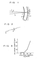
- a conventional color picture tube as shown in Fig. 1, three electron beams 1 to 3 from electron guns (not shown) are correctly radiated onto red, green and blue phosphors 7 to 9 coated on the inner surface of a panel 6 through apertures 5 regularly formed in a shadow mask 4. The phosphors 7 to 9 then emit red, green and blue light to form a color image.
- a shadow mask in a color picture tube of this type must satisfy certain specific requirements. That is, small apertures must be correctly formed in a regular pattern.
- the shadow mask must be curved in a predetermined radius of curvature. The distance (to be referred to as the g value hereinafter) between the shadow mask and the inner surface of the panel must be maintained at a predetermined value.
- the electron beams which pass through the apertures formed in the shadow mask comprise 1/3 or less of the electron beams originally emitted by the electron guns.
- the remaining electron beams bombard against the shadow mask which is, in some cases, thereby heated to a temperature of up to 80°C.
- the shadow mask thermally expands to have a g value different from the predetermined g value, thus causing the dome phenomenon.
- the dome phenomenon occurs, the color purity of the color picture tube is degraded.
- JP-A-42-25446, JP-A-50-58977 and JP-A-50-68650 propose the use of a material which has a small coefficient of thermal expansion, such as an iron-nickel alloy, as the material of a shadow mask.
- this proposal has not yet led to a practical use of such a material in a shadow mask.
- One of the reasons which prevents the use of such a material is the difficulty in working a metal sheet consisting of an iron-nickel alloy.
- the curved surface of the shadow mask must be controlled with high precision.
- the allowable error in a radius of curvature R of 1,000 mm is as small as ⁇ 5 mm.
- An iron-nickel type alloy has an extremely high modulus of elasticity and a high tensile strength after annealing as compared to conventional alloys containing iron as a major component. Accordingly, the iron-nickel type alloy has an inferior curved surface formability by pressing or the like. For example, when a local collapse is formed upon curing an iron-nickel sheet of 0.2 mm thickness to the radius of curvature R as shown in Fig. 2, the degradation in the color purity of the color picture tube is considered negligible if the collapsing quantity d remains 20 pm or less.
- Fig. 3 shows the collapsing quantity d vs yield point strength characteristics of the material of a 14" type shadow mask. It is seen from the graph shown in Fig.
- a shadow mask consisting of an iron-nickel type alloy has a yield point strength (curve b) as shown in Fig. 4, which is significantly higher than that (curve a) of a shadow mask consisting of a conventional AI-killed decarbonized steel in the case where both are annealed in hydrogen in an annealing furnace generally used for the conventional AI-killed decarbonized steel. Even if a shadow mask consisting of an iron-nickel type alloy is annealed at a high temperature of 900°C, the yield point strength is only lowered to 29 to 30 kg/mm 2 .
- Document FR-A-2 231 101 discloses a color picture tube comprising a shadow mask which is formed of a nickel-iron alloy containing 0.1 to 0.5% by weight of manganese.
- a method for manufacturing a color picture tube comprising the steps of: forming a number of apertures in a sheet consisting of an Invar type iron alloy; annealing said sheet in a vacuum of not more than 13,3 Pa (10- 1 Torr) at a temperature of not lower than 1,000°C, so as to reduce a content of manganese in said iron alloy to less than 0.1 % by weight, and to render an austenite grain number both within and at surfaces of said sheet to be not more than 7, said austenite grain number being defined by JIS G 0551 of the Japanese Industrial Standards; forming said sheet after annealing to form a shadow mask; and opposing said shadow mask at a small gap therefrom against a phosphor screen formed on an inner surface of a panel.
- the austenite grain number defined by JIS G 0551 means a grain number representing the size of the austenite crystal grains which is determined by a solid solubilization temperature and a time for maintaining such a solubilization temperature when a steel is heated to a temperature higher than the transformation point or to a temperature of heat treatment for solid solubilization for the purpose of annealing, normalizing and the like.
- Grain number (N) and the number (n) of crystal grains per unit sectional area of mm 2 hold the following relation: Accordingly, when N is 7, n is 1024. When N is 1, n is 16. Thus, the grain size increases proportionally to a decrease in the grain number (N).
- Table 1 shows the composition (% by weight; before annealing) of an Invar alloy used in the Example of the present invention and a conventional AI-killed decarbonized steel.
- Fig. 5 shows the yield point strength as a function of the annealing temperature when a shadow mask sheet consisting of 36Ni Invar alloy having the composition as shown in Table 1 above was heated in a conventional annealing step in a hydrogen atmosphere in an annealing furnace.
- the yield point strength is only reduced to 24 kg/mm 2 .
- extrapolation of the results shown in the graph shown in Fig. 5 reveals that the annealing temperature must fall within the range of 1,500 to 1,700°C.
- the Invar alloy has a melting point of 1,440 to 1,455°C, simple heating to a temperature within the above-mentioned range cannot be performed.
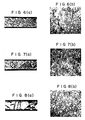
- Figs. 6 to 8 are photomicrographs showing the crystal structure of sample sheets made of an Invar alloy when the annealing was effected in a hydrogen atmosphere 1,000°C, 1,100°C and 1,200°C, respectively, for 10 minutes. The thickness of each sheet was 0.2 mm.
- Figs. 6(a) to 8(a) show sections and Figs. 6(b) to 8(b) show surfaces of the sheets.
- the grain size increases with an increase in the annealing temperature.
- the crystal grains within the sheet had a grain number of 7 as defined by JIS G 0551 when the annealing temperature was 1,000°C, and a grain number of 7 or less when the annealing temperature was 1,100°C and 1,200°C, respectively.
- the grain size within the sheet is seen to increase.
- the grains at the surface of the sheet hardly grow at all and had a grain number of 8 or more even when the annealing temperature was 1,200°C.
- the retarded growth of the crystal grains at the surface is associated with the yield point strength.
- the difference between the growth of crystal grains within and at the surfaces of the sheet is considered to be attributable to slight segregation of impurities in the direction of thickness of the sheet, particularly at the grain boundaries in the vicinity of the surface of the sheet.
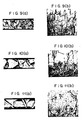
- Figs. 9 to 11 show photomicrographs showing the crystal structure of sample sheets made of an Invar alloy when the sheets were annealed in a vacuum of 0,133 Pa (10- 3 Torr) at 1,000°C, 1,100°C and 1,200°C, respectively, for 10 minutes.
- the thickness of each sheet was 0.2 mm.
- Figs. 9(a) to 11(a) show sections while Figs. 9(b) to 11(b) show surfaces of the sheets.
- crystal grains grow well both within and at the surfaces of the sheets.
- the crystal grains at the surface of the sheet had a grain number of 7 or less, which was the same as that of the grains within the sheet.
- the annealing temperature of about 1,200°C is practical, which results in a grain number of about 3.
- Fig. 12 shows the yield point strength as a function of the annealing temperature used during annealing under vacuum conditions as defined above of an Invar alloy sheet for a shadow mask.
- a yield point strength of 20 kg/mm 2 which is practically satisfactory for curved surface formation, may be obtained by annealing at a temperature higher than 1,000°C.
- Table 2 shows the results of an analysis of impurities in a surface layer (layer having a thickness of 1/20 mm or less) which are considered to prevent satisfactory growth of the crystal grains at the surface of the sheet.
- manganese (Mn) is reduced to about 1/10 its original amount, and phosphorus (P) and sulfur (S) are reduced to undetectable levels.
- Manganese is included in the sheet in order to allow a sheet for a shadow mask to be rolled to a predetermined thickness of 0.1 to 0.3 mm.
- the sheet generally contains 0.3 to 0.5% by weight of manganese.
- the rolling property of the sheet is degraded and cracking tends to occur.
- manganese is not required.
- the presence of manganese impairs the curved surface formability.
- the rolling property of the sheet is considered to be improved by the addition of manganese for the following reasons.
- oxides and the like of the impurities which tend to be formed during annealing in an atmosphere are hardly formed in the surface layer of the sheet.
- crystal grains grow at the same rate both within and in the vicinites of the surfaces of the sheet.
- a color picture tube having a shadow mask prepared in this manner has a coefficient of thermal expansion which is as small as 1 x 10- 6 /deg. to 2 x 10- 6 /deg. at temperatures within the range of 0 to 100°C.
- Mn, Cr, Cu, C and the like increase the coefficient of thermal expansion of Invar alloy. Accordingly, the reduction due to annealing in the amount of Mn is also preferable in this context.
- the above Example is described with reference to a case wherein the sheet for a shadow mask is annealed in a vacuum of 0,133 Pa (10- 3 Torr). However, it was confirmed that a similar effect may be obtained if the vacuum pressure remains at 13,3 Pa (10-' Torr) or less.
- the residual gas in the atmosphere at this vacuum pressure may be an oxidizing gas, a reducing gas, or an inert gas. If the pressure is increased above this critical value, evaporation of the impurities is prevented, and good effect is not obtained.
- the material of the sheet for a shadow mask according to the present invention is not limited to a 36% Ni Invar alloy. Similar effects may be obtained with iron-nickel type alloys such as 42% Ni alloy, a Super Invar obtained by the addition of cobalt to an Fe-Ni alloy, and the like.
- the present invention provides a color picture tube wherein curved surface formability of a shadow mask consisting of an iron-nickel type alloy is improved, and deformation of the shadow mask is prevented, so that the problem of degradation in color purity is eliminated.
Landscapes
- Engineering & Computer Science (AREA)
- Manufacturing & Machinery (AREA)
- Electrodes For Cathode-Ray Tubes (AREA)
- Heat Treatment Of Sheet Steel (AREA)
Description
- The present invention relates to a color picture tube and, more particularly, to a shadow mask thereof and to a method for manufacturing the same.
- In a conventional color picture tube as shown in Fig. 1, three electron beams 1 to 3 from electron guns (not shown) are correctly radiated onto red, green and
blue phosphors 7 to 9 coated on the inner surface of a panel 6 throughapertures 5 regularly formed in a shadow mask 4. Thephosphors 7 to 9 then emit red, green and blue light to form a color image. - A shadow mask in a color picture tube of this type must satisfy certain specific requirements. That is, small apertures must be correctly formed in a regular pattern. The shadow mask must be curved in a predetermined radius of curvature. The distance (to be referred to as the g value hereinafter) between the shadow mask and the inner surface of the panel must be maintained at a predetermined value.
- When the color picture tube is operated, the electron beams which pass through the apertures formed in the shadow mask comprise 1/3 or less of the electron beams originally emitted by the electron guns. The remaining electron beams bombard against the shadow mask which is, in some cases, thereby heated to a temperature of up to 80°C. As a result, the shadow mask thermally expands to have a g value different from the predetermined g value, thus causing the dome phenomenon. When the dome phenomenon occurs, the color purity of the color picture tube is degraded. The material which is conventionally used for a shadow mask and which contains pure iron as a major component, such as AI-killed decarbonized steel, has a coefficient of thermal expansion of about 12 x 10-6/deg. at 0 to 100°C. This material is thus easily vulnerable to the dome phenomenon.
- In view of this problem, JP-A-42-25446, JP-A-50-58977 and JP-A-50-68650 propose the use of a material which has a small coefficient of thermal expansion, such as an iron-nickel alloy, as the material of a shadow mask. However, this proposal has not yet led to a practical use of such a material in a shadow mask. One of the reasons which prevents the use of such a material is the difficulty in working a metal sheet consisting of an iron-nickel alloy. In order that the g value fall within a predetermined allowable range, the curved surface of the shadow mask must be controlled with high precision. The allowable error in a radius of curvature R of 1,000 mm is as small as ±5 mm.
- An iron-nickel type alloy has an extremely high modulus of elasticity and a high tensile strength after annealing as compared to conventional alloys containing iron as a major component. Accordingly, the iron-nickel type alloy has an inferior curved surface formability by pressing or the like. For example, when a local collapse is formed upon curing an iron-nickel sheet of 0.2 mm thickness to the radius of curvature R as shown in Fig. 2, the degradation in the color purity of the color picture tube is considered negligible if the collapsing quantity d remains 20 pm or less. Fig. 3 shows the collapsing quantity d vs yield point strength characteristics of the material of a 14" type shadow mask. It is seen from the graph shown in Fig. 3, that the yield point strength must be suppressed to 20 kg/mm2 or less in order to maintain the collapsing quantity d at 20 um or less. However, a shadow mask consisting of an iron-nickel type alloy has a yield point strength (curve b) as shown in Fig. 4, which is significantly higher than that (curve a) of a shadow mask consisting of a conventional AI-killed decarbonized steel in the case where both are annealed in hydrogen in an annealing furnace generally used for the conventional AI-killed decarbonized steel. Even if a shadow mask consisting of an iron-nickel type alloy is annealed at a high temperature of 900°C, the yield point strength is only lowered to 29 to 30 kg/mm2. Referring to Fig. 3, since no clear boundary was obtained for the yield point strength of the iron-nickel type alloy, a tensile strength after 0.2% elongation is plotted instead. Since a shadow mask consisting of an iron-nickel type alloy has a small coefficient of thermal expansion, degradation in color purity due to a high coefficient of thermal expansion is substantially eliminated. However, degradation in color purity due to deformation and a large collapsing quantity upon curved surface formation still remains.
- Document FR-A-2 231 101 discloses a color picture tube comprising a shadow mask which is formed of a nickel-iron alloy containing 0.1 to 0.5% by weight of manganese.
- It is an object of the present invention to provide a color picture tube having a shadow mask which has a small coefficient of thermal expansion and good curved surface formability, and wherein degradation in color purity due to deformation is eliminated.
- According to an aspect of the present invention, there is provided a color picture tube comprising a shadow mask which is formed to oppose, at a small gap therefrom, a phosphor screen formed on an inner surface of a panel, wherein said shadow mask comprises a sheet of a nickel-containing iron alloy containing manganese of the Invar (= trade name) type, said color picture tube being characterized in that said iron alloy contains less than 0.1 % by weight of manganese, and has an austenite grain number of not more than 7 both within and at surfaces of said sheet, wherein said austenite grain number is defined by JIS G 0551 of the Japanese Industrial Standards.
- According to another aspect of the present invention, there is also provided a method for manufacturing a color picture tube, comprising the steps of: forming a number of apertures in a sheet consisting of an Invar type iron alloy; annealing said sheet in a vacuum of not more than 13,3 Pa (10-1 Torr) at a temperature of not lower than 1,000°C, so as to reduce a content of manganese in said iron alloy to less than 0.1 % by weight, and to render an austenite grain number both within and at surfaces of said sheet to be not more than 7, said austenite grain number being defined by JIS G 0551 of the Japanese Industrial Standards; forming said sheet after annealing to form a shadow mask; and opposing said shadow mask at a small gap therefrom against a phosphor screen formed on an inner surface of a panel.
- In this specification, the austenite grain number defined by JIS G 0551 means a grain number representing the size of the austenite crystal grains which is determined by a solid solubilization temperature and a time for maintaining such a solubilization temperature when a steel is heated to a temperature higher than the transformation point or to a temperature of heat treatment for solid solubilization for the purpose of annealing, normalizing and the like. Grain number (N) and the number (n) of crystal grains per unit sectional area of mm2 hold the following relation:

- This invention can be more fully understood from the following detailed description when taken in conjunction with the accompanying drawings, in which:
- Fig. 1 is a representation for explaining the mode of operation of a color picture tube;
- Fig. 2 is a schematic representation of the main part of a shadow mask for explaining deformation therein;
- Fig. 3 is a graph showing the collapsing quantity as a function of the yield point strength of a shadow mask sheet;
- Figs. 4 and 5 are graphs showing the yield point strength as a function of the annealing temperature of a shadow mask sheet;
- Figs. 6(a) to 8(a) and 6(b) to 8(b) are photomicrographs of sections and surfaces, respectively, of a crystal structure of a shadow mask sheet prepared by a conventional method, the magnification in Figs. 6(a) to 8(a) being 200 times and that in Figs. 6(b) to 8(b) being 240 times;
- Figs. 9(a) to 11(a) and 9(b) to 11(b) are photomicrographs of sections and surfaces, respectively, of a crystal structure of a shadow mask sheet prepared by a method used in the Example of the present invention, the magnification in Figs. 9(a) to 11 (a) being 200 times and that in Figs. 9(b) to 11(b) being 240 times; and
- Fig. 12 is a graph showing the yield point strength as a function of the annealing temperature of the shadow mask sheet prepared in the Example of the present invention.
- The present invention will now be described with reference to an Example wherein an Invar alloy, which contains as a major component an iron-nickel type alloy, is used as a material for a shadow mask. Since the structure of a color picture tube of the present invention is basically the same as that shown in Fig. 1, a detailed description thereof will be omitted.
- Table 1 below shows the composition (% by weight; before annealing) of an Invar alloy used in the Example of the present invention and a conventional AI-killed decarbonized steel.

- Fig. 5 shows the yield point strength as a function of the annealing temperature when a shadow mask sheet consisting of 36Ni Invar alloy having the composition as shown in Table 1 above was heated in a conventional annealing step in a hydrogen atmosphere in an annealing furnace. As may be seen from Fig. 5, even if the sheet is annealed at a temperature as high as 1,200°C, the yield point strength is only reduced to 24 kg/mm2. Accordingly, in order to suppress the yield point strength to 20 kg/mm2 or less which is satisfactory for curved surface formation, extrapolation of the results shown in the graph shown in Fig. 5, reveals that the annealing temperature must fall within the range of 1,500 to 1,700°C. However, since the Invar alloy has a melting point of 1,440 to 1,455°C, simple heating to a temperature within the above-mentioned range cannot be performed.
- Figs. 6 to 8 are photomicrographs showing the crystal structure of sample sheets made of an Invar alloy when the annealing was effected in a hydrogen atmosphere 1,000°C, 1,100°C and 1,200°C, respectively, for 10 minutes. The thickness of each sheet was 0.2 mm.
- Figs. 6(a) to 8(a) show sections and Figs. 6(b) to 8(b) show surfaces of the sheets. As may be seen from the photographs in Figs. 6 to 8, the grain size increases with an increase in the annealing temperature. The crystal grains within the sheet had a grain number of 7 as defined by JIS G 0551 when the annealing temperature was 1,000°C, and a grain number of 7 or less when the annealing temperature was 1,100°C and 1,200°C, respectively. Thus, the grain size within the sheet is seen to increase. However, the grains at the surface of the sheet hardly grow at all and had a grain number of 8 or more even when the annealing temperature was 1,200°C.
- The retarded growth of the crystal grains at the surface is associated with the yield point strength. The difference between the growth of crystal grains within and at the surfaces of the sheet is considered to be attributable to slight segregation of impurities in the direction of thickness of the sheet, particularly at the grain boundaries in the vicinity of the surface of the sheet.
- In the following Example, the sheet was annealed in a vacuum. Figs. 9 to 11 show photomicrographs showing the crystal structure of sample sheets made of an Invar alloy when the sheets were annealed in a vacuum of 0,133 Pa (10-3 Torr) at 1,000°C, 1,100°C and 1,200°C, respectively, for 10 minutes. The thickness of each sheet was 0.2 mm. Figs. 9(a) to 11(a) show sections while Figs. 9(b) to 11(b) show surfaces of the sheets. As may be seen from Figs. 9 to 11, according to this annealing method, crystal grains grow well both within and at the surfaces of the sheets. When the sheet was annealed at a temperature of 1,000°C, the crystal grains at the surface of the sheet had a grain number of 7 or less, which was the same as that of the grains within the sheet. The annealing temperature of about 1,200°C is practical, which results in a grain number of about 3.
- Fig. 12 shows the yield point strength as a function of the annealing temperature used during annealing under vacuum conditions as defined above of an Invar alloy sheet for a shadow mask. A yield point strength of 20 kg/mm2, which is practically satisfactory for curved surface formation, may be obtained by annealing at a temperature higher than 1,000°C.
- Table 2 below shows the results of an analysis of impurities in a surface layer (layer having a thickness of 1/20 mm or less) which are considered to prevent satisfactory growth of the crystal grains at the surface of the sheet.

- As may be seen from Table 2 above, impurities other than iron and nickel in the sheet are mostly decreased after annealing in a vacuum. In particular, manganese (Mn) is reduced to about 1/10 its original amount, and phosphorus (P) and sulfur (S) are reduced to undetectable levels. Manganese is included in the sheet in order to allow a sheet for a shadow mask to be rolled to a predetermined thickness of 0.1 to 0.3 mm. The sheet generally contains 0.3 to 0.5% by weight of manganese.
- When the amount of manganese is less than the lower limit given above, the rolling property of the sheet is degraded and cracking tends to occur. However, after rolling, manganese is not required. In particular, in the case of an iron-nickel type alloy, the presence of manganese impairs the curved surface formability. The rolling property of the sheet is considered to be improved by the addition of manganese for the following reasons. When a sheet for a shadow mask containing impurities such as manganese is annealed in a vacuum, manganese, phosphorus, sulfur and so on which have high vapor pressures are vaporized through grain boundaries to facilitate growth of crystal grains. In addition to this, oxides and the like of the impurities which tend to be formed during annealing in an atmosphere are hardly formed in the surface layer of the sheet. Thus, crystal grains grow at the same rate both within and in the vicinites of the surfaces of the sheet.
- When a sheet for a shadow mask consisting of an Invar alloy, which was obtained by annealing in a vacuum and had a yield point strength of 20 kg/mm2 or less, was formed into a predetermined shape, there occurred no problem in curved surface formability. When the amount of manganese in the sheet after annealing in the vacuum exceeded 0.1% by weight, the curved surface formability of the sheet was confirmed to be impaired. A color picture tube having a shadow mask prepared in this manner has a coefficient of thermal expansion which is as small as 1 x 10⁻⁶/deg. to 2 x 10⁻⁶/deg. at temperatures within the range of 0 to 100°C. Accordingly, such a color picture tube will not suffer from the problem of degradation in color purity due to thermal expansion of the shadow mask and due to mechanical deformation of the shadow mask. In general, Mn, Cr, Cu, C and the like increase the coefficient of thermal expansion of Invar alloy. Accordingly, the reduction due to annealing in the amount of Mn is also preferable in this context.
- The above Example is described with reference to a case wherein the sheet for a shadow mask is annealed in a vacuum of 0,133 Pa (10-3 Torr). However, it was confirmed that a similar effect may be obtained if the vacuum pressure remains at 13,3 Pa (10-' Torr) or less. The residual gas in the atmosphere at this vacuum pressure may be an oxidizing gas, a reducing gas, or an inert gas. If the pressure is increased above this critical value, evaporation of the impurities is prevented, and good effect is not obtained. The material of the sheet for a shadow mask according to the present invention is not limited to a 36% Ni Invar alloy. Similar effects may be obtained with iron-nickel type alloys such as 42% Ni alloy, a Super Invar obtained by the addition of cobalt to an Fe-Ni alloy, and the like.
- In summary, the present invention provides a color picture tube wherein curved surface formability of a shadow mask consisting of an iron-nickel type alloy is improved, and deformation of the shadow mask is prevented, so that the problem of degradation in color purity is eliminated.
Claims (2)
Applications Claiming Priority (6)
| Application Number | Priority Date | Filing Date | Title |
|---|---|---|---|
| JP13572182A JPS5927434A (en) | 1982-08-05 | 1982-08-05 | Color picture tube |
| JP135721/82 | 1982-08-05 | ||
| JP13572282A JPS5927435A (en) | 1982-08-05 | 1982-08-05 | Color picture tube |
| JP13572082A JPS5927433A (en) | 1982-08-05 | 1982-08-05 | Manufacture of shadow mask |
| JP135720/82 | 1982-08-05 | ||
| JP135722/82 | 1982-08-05 |
Publications (2)
| Publication Number | Publication Date |
|---|---|
| EP0101919A1 EP0101919A1 (en) | 1984-03-07 |
| EP0101919B1 true EP0101919B1 (en) | 1986-09-24 |
Family
ID=27317137
Family Applications (1)
| Application Number | Title | Priority Date | Filing Date |
|---|---|---|---|
| EP83107286A Expired EP0101919B1 (en) | 1982-08-05 | 1983-07-25 | Color picture tube and method for manufacturing the same |
Country Status (4)
| Country | Link |
|---|---|
| US (1) | US4708680A (en) |
| EP (1) | EP0101919B1 (en) |
| DE (1) | DE3366460D1 (en) |
| HK (1) | HK109290A (en) |
Families Citing this family (8)
| Publication number | Priority date | Publication date | Assignee | Title |
|---|---|---|---|---|
| JPS59200721A (en) * | 1983-04-27 | 1984-11-14 | Toshiba Corp | Manufacture of shadow mask |
| US4612061A (en) * | 1984-03-15 | 1986-09-16 | Kabushiki Kaisha Toshiba | Method of manufacturing picture tube shadow mask |
| JPS6176651A (en) * | 1984-09-21 | 1986-04-19 | Toshiba Corp | Picture tube |
| US4751424A (en) * | 1987-02-27 | 1988-06-14 | Rca Licensing Corporation | Iron-nickel alloy shadow mask for a color cathode-ray tube |
| CA1319589C (en) * | 1988-08-19 | 1993-06-29 | Masaomi Tsuda | Method of producing fe-ni series alloys having improved effect for restraining streaks during etching |
| FR2641796B1 (en) * | 1988-08-19 | 1993-01-08 | Nippon Yakin Kogyo Co Ltd | PROCESS FOR PRODUCING FE-NI-B SERIES ALLOYS HAVING IMPROVED MODERATOR EFFECT OF THE PRESENCE OF TRAILS DURING ENGRAVING |
| JP2000017393A (en) * | 1998-04-30 | 2000-01-18 | Dainippon Printing Co Ltd | Color CRT shadow mask |
| KR100648712B1 (en) * | 2000-01-03 | 2006-11-23 | 삼성에스디아이 주식회사 | Colored cathode ray tube |
Family Cites Families (11)
| Publication number | Priority date | Publication date | Assignee | Title |
|---|---|---|---|---|
| US3642595A (en) * | 1969-09-23 | 1972-02-15 | Us Air Force | Thermal grain refinement of maraging steel |
| FR2231101A1 (en) * | 1973-05-23 | 1974-12-20 | Metallgesellschaft Ag | Iron-nickel alloys - use as shadow masks for colour television |
| JPS5524227B2 (en) * | 1973-08-08 | 1980-06-27 | ||
| DE2350366A1 (en) * | 1973-10-08 | 1975-04-17 | Metallgesellschaft Ag | Lens mask for colour television tubes - fitted with non-circular or slotted apertures |
| US3909311A (en) * | 1974-08-05 | 1975-09-30 | Hitachi Ltd | Shadow mask for use in color picture tube and method for fabricating same |
| JPS607343B2 (en) * | 1978-10-18 | 1985-02-23 | 日新製鋼株式会社 | Manufacturing method of shadow mask for color television cathode ray tube |
| JPS5569238A (en) * | 1978-11-15 | 1980-05-24 | Nisshin Steel Co Ltd | Steel for shadow mask of color television braun tube |
| US4210843A (en) * | 1979-04-03 | 1980-07-01 | Zenith Radio Corporation | Color CRT shadow mask and method of making same |
| JPS5943974B2 (en) * | 1979-08-22 | 1984-10-25 | 日本鋼管株式会社 | How to make a shadow mask |
| DE3124366A1 (en) * | 1981-06-20 | 1982-12-30 | Hoechst Ag, 6000 Frankfurt | N-OXACYCLYL-ALKYLPIPERIDIN DERIVATIVES, METHOD FOR THE PRODUCTION THEREOF, PHARMACEUTICAL PREPARATIONS CONTAINING IT AND THE USE THEREOF |
| JPS59200721A (en) * | 1983-04-27 | 1984-11-14 | Toshiba Corp | Manufacture of shadow mask |
-
1983
- 1983-07-25 DE DE8383107286T patent/DE3366460D1/en not_active Expired
- 1983-07-25 EP EP83107286A patent/EP0101919B1/en not_active Expired
-
1986
- 1986-01-13 US US06/818,269 patent/US4708680A/en not_active Expired - Lifetime
-
1990
- 1990-12-27 HK HK1092/90A patent/HK109290A/en not_active IP Right Cessation
Also Published As
| Publication number | Publication date |
|---|---|
| EP0101919A1 (en) | 1984-03-07 |
| US4708680A (en) | 1987-11-24 |
| DE3366460D1 (en) | 1986-10-30 |
| HK109290A (en) | 1991-01-04 |
Similar Documents
| Publication | Publication Date | Title |
|---|---|---|
| US4536226A (en) | Method of manufacturing a shadow mask for a color cathode ray tube | |
| JP2007231423A (en) | Method for producing an iron / nickel alloy shadow mask | |
| US4612061A (en) | Method of manufacturing picture tube shadow mask | |
| US4708680A (en) | Color picture tube and method for manufacturing the same | |
| KR0135060B1 (en) | Shadow mask plate material and shadow mask | |
| EP0176344B1 (en) | Colour picture tube | |
| EP0627494B1 (en) | Alloy sheet for shadow mask and method for manufacturing thereof | |
| KR930004684B1 (en) | Color CRT | |
| JPS5927435A (en) | Color picture tube | |
| US5578898A (en) | Shadow mask and cathode ray tube | |
| KR960010427B1 (en) | Method of annealing an aperture shadow mask for a color cathode ray tube | |
| KR20040045877A (en) | FeNi BASE ALLOY FOR SHADOW MASK RAW MATERIAL EXCELLENT IN CORROSION RESISTANCE AND SHADOW MASK MATERIAL | |
| JP2669789B2 (en) | In-pipe parts | |
| JPH0676645B2 (en) | Material for pipe parts and manufacturing method thereof | |
| JPS6142838A (en) | Color picture tube | |
| JPS61218050A (en) | Material for the parts of color television picture tube and their manufacture | |
| JPH10219409A (en) | Inner shield material for magnetic shield and its manufacturing method | |
| JP3469559B2 (en) | Fe-Ni-Co alloy for flat masks with excellent low thermal expansion after blackening | |
| JPS643022B2 (en) | ||
| JPH0687398B2 (en) | Method for manufacturing shed mask | |
| JPH10214578A (en) | Heat shrink band | |
| KR930007092B1 (en) | Manufacturing method of Fe-Ni alloy material for shadow mask | |
| JPH0798982B2 (en) | Manufacturing method of in-pipe parts | |
| JP2001011574A (en) | Hot rolled steel sheet for TV cathode ray tube frame and method of manufacturing the same | |
| JPH0610323B2 (en) | Material for low thermal expansion type shadow mask and its manufacturing method |
Legal Events
| Date | Code | Title | Description |
|---|---|---|---|
| PUAI | Public reference made under article 153(3) epc to a published international application that has entered the european phase |
Free format text: ORIGINAL CODE: 0009012 |
|
| 17P | Request for examination filed |
Effective date: 19830822 |
|
| AK | Designated contracting states |
Designated state(s): DE FR GB |
|
| RAP1 | Party data changed (applicant data changed or rights of an application transferred) |
Owner name: KABUSHIKI KAISHA TOSHIBA |
|
| GRAA | (expected) grant |
Free format text: ORIGINAL CODE: 0009210 |
|
| AK | Designated contracting states |
Kind code of ref document: B1 Designated state(s): DE FR GB |
|
| REF | Corresponds to: |
Ref document number: 3366460 Country of ref document: DE Date of ref document: 19861030 |
|
| ET | Fr: translation filed | ||
| PLBE | No opposition filed within time limit |
Free format text: ORIGINAL CODE: 0009261 |
|
| STAA | Information on the status of an ep patent application or granted ep patent |
Free format text: STATUS: NO OPPOSITION FILED WITHIN TIME LIMIT |
|
| 26N | No opposition filed | ||
| REG | Reference to a national code |
Ref country code: GB Ref legal event code: 746 Effective date: 19990216 |
|
| REG | Reference to a national code |
Ref country code: FR Ref legal event code: D6 |
|
| REG | Reference to a national code |
Ref country code: GB Ref legal event code: IF02 |
|
| PGFP | Annual fee paid to national office [announced via postgrant information from national office to epo] |
Ref country code: FR Payment date: 20020709 Year of fee payment: 20 |
|
| PGFP | Annual fee paid to national office [announced via postgrant information from national office to epo] |
Ref country code: GB Payment date: 20020724 Year of fee payment: 20 |
|
| PGFP | Annual fee paid to national office [announced via postgrant information from national office to epo] |
Ref country code: DE Payment date: 20020731 Year of fee payment: 20 |
|
| PG25 | Lapsed in a contracting state [announced via postgrant information from national office to epo] |
Ref country code: GB Free format text: LAPSE BECAUSE OF EXPIRATION OF PROTECTION Effective date: 20030724 |
|
| REG | Reference to a national code |
Ref country code: GB Ref legal event code: PE20 |