EP0101883A1 - Method for acoustical position deviation measurement - Google Patents
Method for acoustical position deviation measurement Download PDFInfo
- Publication number
- EP0101883A1 EP0101883A1 EP83107061A EP83107061A EP0101883A1 EP 0101883 A1 EP0101883 A1 EP 0101883A1 EP 83107061 A EP83107061 A EP 83107061A EP 83107061 A EP83107061 A EP 83107061A EP 0101883 A1 EP0101883 A1 EP 0101883A1
- Authority
- EP
- European Patent Office
- Prior art keywords
- ship
- relay
- acoustic
- board
- response
- Prior art date
- Legal status (The legal status is an assumption and is not a legal conclusion. Google has not performed a legal analysis and makes no representation as to the accuracy of the status listed.)
- Granted
Links
Images


Classifications
-
- G—PHYSICS
- G01—MEASURING; TESTING
- G01S—RADIO DIRECTION-FINDING; RADIO NAVIGATION; DETERMINING DISTANCE OR VELOCITY BY USE OF RADIO WAVES; LOCATING OR PRESENCE-DETECTING BY USE OF THE REFLECTION OR RERADIATION OF RADIO WAVES; ANALOGOUS ARRANGEMENTS USING OTHER WAVES
- G01S15/00—Systems using the reflection or reradiation of acoustic waves, e.g. sonar systems
- G01S15/87—Combinations of sonar systems
- G01S15/876—Combination of several spaced transmitters or receivers of known location for determining the position of a transponder or a reflector
-
- G—PHYSICS
- G01—MEASURING; TESTING
- G01S—RADIO DIRECTION-FINDING; RADIO NAVIGATION; DETERMINING DISTANCE OR VELOCITY BY USE OF RADIO WAVES; LOCATING OR PRESENCE-DETECTING BY USE OF THE REFLECTION OR RERADIATION OF RADIO WAVES; ANALOGOUS ARRANGEMENTS USING OTHER WAVES
- G01S15/00—Systems using the reflection or reradiation of acoustic waves, e.g. sonar systems
- G01S15/87—Combinations of sonar systems
- G01S15/874—Combination of several spaced transponders or reflectors of known location for determining the position of a receiver
Definitions
- the present invention relates to an acoustic deviation measurement device, intended mainly for measuring the position deviation of a ship relative to a fixed point on the bottom of the water; the result of the measurement is supplied to a system for dynamic positioning of the ship relative to said point.
- the invention also relates to a method of implementing the device.
- an acoustic transceiver E ' is placed under the ship and interrogates answering machines A', B ', C' placed at the bottom of the water near the fixed point.
- the devices which have just been described cannot be used when the ship is itself a significant source of noise (ship or drilling platform for example) and that the sea depth exceeds 3000 meters.
- the signal received by the on-board hydrophone greatly attenuated by its long journey in the water, is dominated by the surrounding noise so that if no modification is made to the device, the processing of the signals becomes impossible.
- a first modification envisaged is to increase the power of the responder (s); However, if an answering machine of the current type at 25 kHz requires a power of 4 kW when operating at 3000 meters deep, it requires a power of 2000 kW at 6000 meters deep, knowing that the attenuation of a sound signal is 7 dB / km; indeed, compared to a source placed at 3000 meters, a source at 6000 meters provides on the surface a signal whose attenuation, expressed in dB is 20 log 6000 (divergence), increased by 7 x 3, or about 27 dB . Providing the responder (s) with a power of the order of a thousand kW is not possible, if we know that the installations must be able to operate for several months without interruption.
- a second modification envisaged is to use directional responders operating at a lower frequency (for example 10 to 12 kHz), for which the propagation takes place with a lower attenuation - (1.5 dB / km).
- the aims of the present invention are therefore to make acoustic deviation measurements for noisy ships and large bottoms (more than 3000 meters and in particular 6000 meters deep), without modifying the existing devices and without providing them with a significant increase in power.
- the subject of the present invention is a device for measuring acoustic deviation intended for measuring the deviations taken by a ship with respect to the vertical of a fixed point of the bottom of the water, comprising, fixed under the ship, a acoustic emitter and at least three receivers arranged at the vertices of a plane polygon, further comprising, placed at the bottom of the water in the vicinity of said fixed point and at the vertices of a polygon at least three acoustic transceivers characterized in that it comprises immersed in near the ship and at a depth at which the ship's own noise is very attenuated, a relay acoustic transceiver receiving waves from the on-board transmitter and transmitting in response to the on-board receivers acoustic signals processed by an organ calculation which deduces the differences in the various acoustic paths between the relay transceiver and the on-board receivers, said background transceivers, transmitting in response to the on-board transmitter and successively, thanks to
- the background transceivers are provided with means of inhibition for given times after a transmission.
- they have a threshold below which they emit no response.
- the relay transceiver is directional downward so as to have a strong attenuation for the signals coming from the top.
- Background transmitters only respond to reception of their own code or a given frequency equal to that to which they transmit in response.
- the relay transceiver responds to reception of the codes of the background transceivers as well as to reception of the transmission frequency of these background transceivers.
- the relay transceiver outputs a signal at a frequency different from the transmission frequency of the background transmitters.
- the invention also relates to a method for implementing the above device.
- FIG. 3 is an explanatory diagram of the invention which shows the various constituent elements of the device of the invention and which illustrates its method of implementation.
- the vessel N is, for example, a vessel (or a drilling platform) associated with dynamic anchoring means which require knowledge for their implementation, at close time intervals (for example of the order of second) of its position relative to a bottom point, which for example is the entry P of a wellbore.
- the device of the invention comprises three series of organs:
- hydrophones There are at least three acoustic receivers (hydrophones) arranged in a horizontal triangle H1, H2, H3. In ships where there are already four hydrophones arranged in a rectangle, three hydrophones will be used in normal service, the fourth being used as a backup in the event of failure of one of the other three.
- hydrophones ensure the detection of the arrival time of acoustic pulses of given shape emitted at a given frequency f1 (for example 32 kHz).
- At least one acoustic transmitter I Under the ship is placed at least one acoustic transmitter I. It is an interrogation transducer emitting an audible signal constituting an interrogation code and produced by an appropriate combination of two or three frequencies (7, 9 and 11 kHz for example). Some ships are fitted with two transducers of the aforementioned type. In this case, only one will be used in normal operation, the second being used as a backup in case of failure of the first.
- At the bottom of the sea are arranged at least three acoustic responders A, B, C respectively responding to an interrogation by code a, b and c. They are arranged in a triangle in the vicinity of point P.
- the sides of the triangle are approximately equal and of length preferably between 5 and 8% of the depth of the sea. For a depth of 6000 meters, sides will be taken between 300 and 500 meters.
- the acoustic responders A, B, C are placed by dropping from the ship or from an auxiliary ship. We assume that the distances AB, BC and CA are known (we will show later how we can access this knowledge).
- an acoustic relay transceiver R is arranged. This transmitter will preferably be submerged at a depth h close to 7% of the depth of the sea at the location considered, which for a depth of 6000 meters, leads to placing the relay transceiver at about 400 meters from the level. of the sea.
- the suspension is made either by means of a buoy attached to the ship at about 200 meters, or (case of the figure) to a crane of the boat.
- a buoy attached to the ship at about 200 meters, or (case of the figure) to a crane of the boat.
- responders A, B and C are assumed to be known (lengths of the sides of the triangle, orientation relative to the north); we will see later how to reach this knowledge.
- the transducer I emits one of the codes a, b or c, for example the code a.
- Relay R detects code a and responds with a transmission at frequency f1.
- the responses (paths 1, 2 and 3 in Figure 3) are detected by the hydrophones H1, H2 and H3 and from these responses the distances RH1, RH2 and RH3 are calculated. Knowing moreover the orientation of the ship, the coordinates of point R are determined without ambiguity. (The calculation is the same as that performed with a classic short base as in Figure 1).
- Responder A detects its code a and in response sends a pulse to f2, which triggers responses at frequency f2 from the other two hydrophones B and C.
- the responses, sent with the timers specific to each background transmitter, are received by the relay R which, in response, retransmits at the frequency f1; one of the hydrophones (H1 in the case of the figure) receives this retransmission (path 4 of FIG. 3) and transmits from the ship to the computer which deduces the differences in the paths RB-RA, RC-RA, RB-RC and consequently the lengths of the edges of the RABC pyramid, knowing the depth h of immersion of the relay and the depth H of the seabed.
- the device of the invention makes it possible to solve the problem posed by the noise of the ship.
- the device of the invention makes it possible to obtain a position measurement approximately every second; the device operates as long as the ship does not deviate by more than 300 meters + 10% of the sea depth, which makes the device applicable for all types of known operations, in particular for dynamic anchoring above a set point.
- the device only requires conventional equipment that has already been tested.
- responders A, B and C cannot respond to signals emitted by one of their neighbors and reflected on the surface of the sea.
- the travel time of such signals is much greater than the duration of inhibition of the responders; but the level of these signals is however much lower than the operating threshold of the responders, due to the attenuation due to the long journey in the water.
- Relay R cannot respond to an emission from A or B and reflected on the surface of the sea because of the directivity of the transducer with which it is equipped and which attenuates by at least 30dB an already weakened signal by 5dB compared to direct arrival.
- Another relay R ' (not shown) is used for this, arranged at a known distance from R and in a known RR' orientation.
- the characteristics of the pyramid R'ABC are then measured using the transmitter I, and as indicated in the description of the operation of the device of the invention.
- the end of the drill string can be fitted with a hydrophone 0 capturing the emissions at f2 resulting from the interrogation of one of the hydrophones A, B or C.
- Hydrophone 0 connected by cable to the vessel then transmits signals corresponding to the differences in journey times OA-OB, OA-OC, OB-OC.
Abstract
L'invention a pour objet un dispositif de mesure d'écartométrie acoustique destiné à mesurer les écarts pris par un navire N par rapport à la verticale d'un point fixe (P) du fond de l'eau, comprenant, fixés sous le navire, un organe émetteur (I) acoustique et au moins trois récepteurs (H1, H2, H3) disposés aux sommets d'un polygone plan, comprenant en outre, placés au fond de l'eau au voisinage dudit point fixe (P), et aux sommets d'un polygone au moins trois émetteurs-récepteurs (A, B, C) acoustiques, caractérisé par le fait qu'il comprend, immergé à proximité du navire et à une profondeur à laquelle les bruits propres du navire sont très atténués, un émetteur-récepteur acoustique (R) relais recevant des ondes de l'émetteur de bord (I) et émettant en réponse en direction des recepteurs de bord (H1, H2, H3) des signaux acoustiques traités par un organe de calcul qui en déduit les écarts des divers trajets acoustiques (RH1, RH2, RH3) entre l'émetteur-récepteur relais (R) et les récepteurs embarqués (H1, H2, H3), lesdits émetteurs-récepteurs de fond (A, B, C) émettant en réponse à l'émetteur de bord (I) et successivement, grâce à des temporisations prédéterminées, des signaux acoustiques séquentiels qui sont reçus par l'émetteur-récepteur relais (R) et qui sont réémis par celui-ci après amplification, vers l'un des récepteurs de bord (H1), les signaux reçus étant traités par l'organe de calcul qui en déduit les différences des temps de trajet (RA, RB, RC) entre le relais (R) et les émetteurs récepteurs de fond (A, B, C), les deux jeux de différences précités étant traités par l'organe de calcul pour élaborer l'écart du navire par rapport à la verticale dudit point fixe. Application à l'ancrage dynamique des navires.The subject of the invention is an acoustic deviation measurement device intended to measure the deviations taken by a ship N with respect to the vertical of a fixed point (P) of the water bottom, comprising, fixed under the ship , an acoustic emitting member (I) and at least three receivers (H1, H2, H3) disposed at the vertices of a plane polygon, further comprising, placed at the bottom of the water in the vicinity of said fixed point (P), and at the vertices of a polygon at least three acoustic transceivers (A, B, C), characterized in that it comprises, immersed close to the ship and at a depth at which the ship's own noise is very attenuated, an acoustic transceiver (R) relay receiving waves from the on-board transmitter (I) and transmitting in response towards the on-board receivers (H1, H2, H3) acoustic signals processed by a calculation unit which deduces therefrom the deviations of the various acoustic paths (RH1, RH2, RH3) between the relay transceiver (R) and receives them on-board urs (H1, H2, H3), said bottom transceivers (A, B, C) transmitting in response to the on-board transmitter (I) and successively, thanks to predetermined time delays, sequential acoustic signals which are received by the relay transceiver (R) and which are retransmitted by it after amplification, to one of the on-board receivers (H1), the signals received being processed by the calculation unit which deduces the differences therefrom travel times (RA, RB, RC) between the relay (R) and the background transmitters-receivers (A, B, C), the two sets of differences mentioned above being processed by the calculation unit to work out the difference of the ship with respect to the vertical of said fixed point. Application to the dynamic anchoring of ships.
Description
La présente invention est relative à un dispositif d'écartométrie acoustique, destiné principalement à mesurer l'écart de position d'un navire par rapport à un point fixe du fond de l'eau ; le résultat de la mesure est fourni à un système de positionnement dynamique du navire par rapport audit point. L'invention est également relative à un procédé de mise en oeuvre du dispositif.The present invention relates to an acoustic deviation measurement device, intended mainly for measuring the position deviation of a ship relative to a fixed point on the bottom of the water; the result of the measurement is supplied to a system for dynamic positioning of the ship relative to said point. The invention also relates to a method of implementing the device.
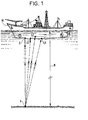
Les dispositifs d'écartométrie acoustique connus comprennent essentiellement (figure 1) un émetteur E d'ondes acoustiques placé sur le navire N et émettant vers le fond en direction d'un répondeur acoustique S placé au fond de l'eau au point fixe ou à son voisinage. Le répondeur S émet, en réponse aux signaux sonores reçus, une impulsion qui est reçue par un groupe d'hydrophones L1, L2, L3 disposés sous le navire selon un polygone. La mesure des différences de temps de parcours des trajets acoustiques SL1, SL2, SL3 séparant le répondeur du fond des hydrophones de bord permet, connaissant en outre l'une au moins des distances L1 L2, L2 L3, L1 L3 séparant les hydrophones ou la profondeur H de l'eau, de déterminer l'écart entre la verticale passant par l'émetteur de bord et le répondeur du fond. On se référera pour plus de détail sur le calcul aux publications ci-après :
- - Système d'ancrage dynamique du PELICAN. Colloque GRETSI, Nice 1973, par Claude LEROY.
- - Localisation sous-marine précise dans les trois dimensions. Colloque GRETSI, Nice 1973 par Claude LEROY.
- - Acoustic measuring system and its performances. Preprints of the 1974 OTC Conférence Vol 1 6-8 Mai 1974. Houston Texas par Claude DI GIACOMO, Claude LEROY et Jean PROST.
- - PELICAN dynamic anchoring system. GRETSI conference, Nice 1973, by Claude LEROY.
- - Precise underwater location in three dimensions. GRETSI conference, Nice 1973 by Claude LEROY.
- - Acoustic measuring system and its performances. Preprints of the 1974 OTC Conférence Vol 1 May 6-8, 1974. Houston Texas by Claude DI GIACOMO, Claude LEROY and Jean PROST.
Dans d'autres dispositifs d'écartométrie connus (figure 2), un émetteur récepteur acoustique E' est placé sous le navire et interroge des répondeurs A', B', C' disposés au fond de l'eau au voisinage du point fixe. La mesure des écarts de trajet E'A', E'B', E'C' conduit aux mêmes résultats que précédemment.In other known deviation measurement devices (FIG. 2), an acoustic transceiver E 'is placed under the ship and interrogates answering machines A', B ', C' placed at the bottom of the water near the fixed point. The measurement of the path deviations E'A ', E'B', E'C 'leads to the same results as above.
Les dispositifs qui viennent d'être décrits sont inutilisables lorsque le navire est lui-même une source importante de bruit (navire ou plate-forme de forage par exemple) et que la profondeur de la mer dépasse 3000 mètres.The devices which have just been described cannot be used when the ship is itself a significant source of noise (ship or drilling platform for example) and that the sea depth exceeds 3000 meters.
En effet, le signal reçu par le ou les hydrophones de bord, très atténué par son long trajet dans l'eau, est dominé par le bruit environnant de telle sorte que si aucune modification n'est apportée au dispositif, l'exploitation des signaux devient impossible.Indeed, the signal received by the on-board hydrophone (s), greatly attenuated by its long journey in the water, is dominated by the surrounding noise so that if no modification is made to the device, the processing of the signals becomes impossible.
Une première modification envisagée est d'augmenter la puissance du (ou des) répondeurs ; or si un répondeur de type courant à 25 kHz nécessite une puissance de 4 kW lorsqu'il fonctionne à 3000 mètres de profondeur, il exige une puissance de 2000 kW à 6000 mètres de profondeur, sachant que l'atténuation d'un signal sonore est de 7 dB/km ; en effet, par rapport à une source placée à 3000 mètres, une source à 6000 mètres fournit en surface un signal dont l'affaiblissement, exprimé en dB est de 20 log 6000 (divergence), augmenté de 7 x 3, soit environ 27 dB. Doter le (ou les) répondeurs d'une puissance de l'ordre du millier de kW n'est pas envisageable, si on sait que les installations doivent pouvoir fonctionner plusieurs mois sans interruption.A first modification envisaged is to increase the power of the responder (s); However, if an answering machine of the current type at 25 kHz requires a power of 4 kW when operating at 3000 meters deep, it requires a power of 2000 kW at 6000 meters deep, knowing that the attenuation of a sound signal is 7 dB / km; indeed, compared to a source placed at 3000 meters, a source at 6000 meters provides on the surface a signal whose attenuation, expressed in dB is 20 log 6000 (divergence), increased by 7 x 3, or about 27 dB . Providing the responder (s) with a power of the order of a thousand kW is not possible, if we know that the installations must be able to operate for several months without interruption.
Une seconde modification envisagée est d'utiliser des répondeurs directifs fonctionnant à plus basse fréquence, (par exemple 10 à 12 kHz), pour lesquels la propagation se fait avec une atténuation plus faible - (1,5 dB/km).A second modification envisaged is to use directional responders operating at a lower frequency (for example 10 to 12 kHz), for which the propagation takes place with a lower attenuation - (1.5 dB / km).
Cette solution n'est pas souhaitable, car elle nécessite des études importantes de mise au point et de fabrication d'un nouveau répondeur et conduit à une précision de mesure inférieure.This solution is not desirable, because it requires significant studies to develop and manufacture a new transponder and leads to lower measurement accuracy.
Par ailleurs, elle nécessite le remplacement des hydrophones existants, ce qui revient à rendre périmés les matériels existants.Furthermore, it requires the replacement of existing hydrophones, which amounts to making existing equipment obsolete.
Les buts de la présente invention sont donc de faire des mesures d'écartométrie acoustique pour des navires bruyants et des fonds importants (plus de 3000 mètres et en particulier 6000 Mètres de profondeur), sans modifier les appareils existants et sans les doter d'un accroissement de puissance important.The aims of the present invention are therefore to make acoustic deviation measurements for noisy ships and large bottoms (more than 3000 meters and in particular 6000 meters deep), without modifying the existing devices and without providing them with a significant increase in power.
La présente invention a pour objet un dispositif de mesure d'écar- tométrie acoustique destiné à mesurer les écarts pris par un navire par rapport à la verticale d'un point fixe du fond de l'eau, comprenant, fixés sous le navire, un organe émetteur acoustique et au moins trois récepteurs disposés aux sommets d'un polygone plan, comprenant en outre, placés au fond de l'eau au voisinage dudit point fixe et aux sommets d'un polygone au moins trois émetteurs-récepteurs acoustiques caractérisé par le fait qu'il comprend immergé à proximité du navire et à une profondeur à laquelle les bruits propres du navire sont très atténués, un émetteur-récepteur acoustique relais recevant des ondes de l'émetteur de bord et émettant en réponse en direction des récepteurs de bord des signaux acoustiques traités par un organe de calcul qui en déduit les écarts des divers trajets acoustiques entre l'émetteur-récepteur relais et les récepteurs embarqués, lesdits émetteurs-récepteurs de fond, émettant en réponse à l'émetteur de bord et successivement, grâce à des temporisations prédéterminées, des signaux acoustiques, séquentiels qui sont reçus par l'émetteur-récepteur relais et qui sont réémis par celui-ci après amplification, vers l'un des récepteurs de bord, les signaux reçus étant traités par l'organe de calcul qui en déduit les différences des temps de trajet entre le relais et les émetteurs récepteurs de fond, les deux jeux de différences précités étant traités par l'organe de calcul pour élaborer l'écart du navire par rapport à la verticale dudit point fixe.The subject of the present invention is a device for measuring acoustic deviation intended for measuring the deviations taken by a ship with respect to the vertical of a fixed point of the bottom of the water, comprising, fixed under the ship, a acoustic emitter and at least three receivers arranged at the vertices of a plane polygon, further comprising, placed at the bottom of the water in the vicinity of said fixed point and at the vertices of a polygon at least three acoustic transceivers characterized in that it comprises immersed in near the ship and at a depth at which the ship's own noise is very attenuated, a relay acoustic transceiver receiving waves from the on-board transmitter and transmitting in response to the on-board receivers acoustic signals processed by an organ calculation which deduces the differences in the various acoustic paths between the relay transceiver and the on-board receivers, said background transceivers, transmitting in response to the on-board transmitter and successively, thanks to predetermined time delays, signals acoustic, sequential signals which are received by the relay transceiver and which are retransmitted by the latter after amplification, towards one of the on-board receivers, the signals received and ant processed by the calculating unit which deduces therefrom the differences in the journey times between the relay and the downhole transceivers, the two aforementioned sets of differences being processed by the calculating body to work out the deviation of the ship from vertical to said fixed point.
Avantageusement, les émetteurs-récepteurs de fond sont munis de moyens d'inhibition pendant des temps donnés après une émission. De plus ils sont dotés d'un seuil au-dessous duquel ils n'émettent aucune réponse.Advantageously, the background transceivers are provided with means of inhibition for given times after a transmission. In addition, they have a threshold below which they emit no response.
L'émetteur-récepteur relais est directif vers le bas de manière à posséder une forte atténuation pour les signaux venant du haut.The relay transceiver is directional downward so as to have a strong attenuation for the signals coming from the top.
Les émetteurs-récepteurs de fond ne répondent qu'à réception d'un code qui leur est propre ou d'une fréquence donnée égale à celle à laquelle ils émettent en réponse.Background transmitters only respond to reception of their own code or a given frequency equal to that to which they transmit in response.
L'émetteur-récepteur relais répond à réception des codes des émetteurs-récepteurs de fond ainsi qu'à réception de la fréquence d'émission de ces émetteurs-récepteurs de fond.The relay transceiver responds to reception of the codes of the background transceivers as well as to reception of the transmission frequency of these background transceivers.
L'émetteur-récepteur relais émet en réponse un signal à une fréquence différente de la fréquence d'émission des émetteurs-récepteurs de fond.The relay transceiver outputs a signal at a frequency different from the transmission frequency of the background transmitters.
L'invention concerne également un procédé pour la mise en oeuvre du dispositif ci-dessus.The invention also relates to a method for implementing the above device.
L'invention est précisée par la description ci-après d'un exemple préféré de réalisation de l'invention en référence au dessin ci annexé dans lequel :
- - les figures 1 et 2 sont des illustrations des dispositifs connus d'écartométrie
- - la figure 3 est un schéma montrant les positions des divers éléments du dispositif de l'invention avec figuration des trajets des signaux émis.
- - Figures 1 and 2 are illustrations of known devices for deviation measurement
- - Figure 3 is a diagram showing the positions of the various elements of the device of the invention with figuration of the paths of the signals transmitted.
La figure 3 est un schéma explicatif de l'invention qui montre les divers éléments constitutifs du dispositif de l'invention et qui illustre son procédé de mise en oeuvre.FIG. 3 is an explanatory diagram of the invention which shows the various constituent elements of the device of the invention and which illustrates its method of implementation.
Le navire N est par exemple un bâtiment (ou une plate-forme de forage) associé à des moyens d'ancrage dynamique qui nécessitent pour leur mise en oeuvre la connaissance, à des intervalles de temps rapprochés (par exemple de l'ordre de la seconde) de sa position par rapport à un point de fond, qui par exemple est l'entrée P d'un puits de forage.The vessel N is, for example, a vessel (or a drilling platform) associated with dynamic anchoring means which require knowledge for their implementation, at close time intervals (for example of the order of second) of its position relative to a bottom point, which for example is the entry P of a wellbore.
On rappelle que les conditions d'exploitation contiennent deux contraintes irréductibles :
- a/ le bateau émet du bruit à un niveau élevé notamment par ses moteurs de positionnement et d'entraînement du train de tiges qui viennent s'ajouter au bruit de la mer.
- b/ la profondeur est supérieure à 3000 mètres.
- a / the boat emits noise at a high level, in particular through its positioning and rod train motors which add to the noise of the sea.
- b / the depth is greater than 3000 meters.
Le dispositif de l'invention comprend trois séries d'organes :The device of the invention comprises three series of organs:
Il y a au moins trois récepteurs acoustiques (hydrophones) disposés selon un triangle horizontal H1, H2, H3. Dans les navires où il existe déjà quatre hydrophones disposés en rectangle, on utilisera trois hydrophones en service normal, le quatrième étant utilisé en secours en cas de panne de l'un des trois autres.There are at least three acoustic receivers (hydrophones) arranged in a horizontal triangle H1, H2, H3. In ships where there are already four hydrophones arranged in a rectangle, three hydrophones will be used in normal service, the fourth being used as a backup in the event of failure of one of the other three.
Ces hydrophones assurent la détection de l'instant d'arrivée d'impulsions acoustiques de forme donnée émises à une fréquence donnée f1 (par exemple 32 kHz).These hydrophones ensure the detection of the arrival time of acoustic pulses of given shape emitted at a given frequency f1 (for example 32 kHz).
Sous le navire est placé au moins un émetteur acoustique I. Il s'agit d'un transducteur d'interrogation émettant un signal sonore constituant un code d'interrogation et réalisé par une combinaison appropriée de deux ou trois fréquences (7, 9 et 11 kHz par exemple). Certains navires sont équipés de deux transducteurs du type précité. Dans ce cas un seul sera utilisé en fonctionnement normal, le second étant utilsé en secours en cas de panne du premier.Under the ship is placed at least one acoustic transmitter I. It is an interrogation transducer emitting an audible signal constituting an interrogation code and produced by an appropriate combination of two or three frequencies (7, 9 and 11 kHz for example). Some ships are fitted with two transducers of the aforementioned type. In this case, only one will be used in normal operation, the second being used as a backup in case of failure of the first.
Nous désignerons par a, b, c trois codes utilisés par le transducteur I.We will designate by a, b, c three codes used by the transducer I.
Au fond de la mer sont disposés au moins trois répondeurs acoustiques A, B, C répondant respectivement à une interrogation par code a, b et c. Ils sont disposés selon un triangle au voisinage du point P.At the bottom of the sea are arranged at least three acoustic responders A, B, C respectively responding to an interrogation by code a, b and c. They are arranged in a triangle in the vicinity of point P.
Les côtés du triangle sont à peu près égaux et de longueur comprise de préférence entre 5 et 8% de la profondeur de la mer. Pour une profondeur de 6000 mètres, on prendra des côtés entre 300 et 500 mètres. Les répondeurs acoustiques A, B, C sont placés par largage depuis le navire ou depuis un navire auxiliaire. On suppose que les distances AB, BC et CA sont connues (on montrera plus loin comment on peut avoir accès à cette connaissance).The sides of the triangle are approximately equal and of length preferably between 5 and 8% of the depth of the sea. For a depth of 6000 meters, sides will be taken between 300 and 500 meters. The acoustic responders A, B, C are placed by dropping from the ship or from an auxiliary ship. We assume that the distances AB, BC and CA are known (we will show later how we can access this knowledge).
Les caractéristiques acoustiques des répondeurs A, B, C sont les suivantes
- A/ ils répondent par une impulsion de niveau et forme déterminée à une fréquence donnée f2 (par exemple 25 kHz) dans les deux cas suivants :
- 1. réception de leur code propre d'interrogation a, b, c, comme il a déjà été fait mention plus haut.
- 2. détection, au-dessus d'un seuil donné d'une impulsion à la fréquence f2 émise par l'un quelconques de leurs voisins A, B, C.
- B/ Une fois une impulsion émise pour l'une des deux raisons énoncées en A/, les répondeurs sont rendus inactifs pendant une durée donnée fixe (par exemple une seconde) imposée par les dimensions maximales du polygone ABC.
- C/ l'émission à la fréquence f2 d'une impulsion se fait avec un certain retard par rapport à l'instant d'arrivée de la cause qui l'a déclenchée ; les divers répondeurs ont des temps de retard différents (tA pour A, tB pour B, tC pour C) de telle aorte que les réponses soient émisent selon une séquence déterminée permettant l'identification ultérieure des impulsions.
- A / they respond with a level and shape pulse determined at a given frequency f2 (for example 25 kHz) in the following two cases:
- 1. receipt of their own interrogation code a, b, c, as already mentioned above.
- 2. detection, above a given threshold of a pulse at the frequency f2 emitted by any one of their neighbors A, B, C.
- B / Once an impulse is emitted for one of the two reasons stated in A /, the responders are made inactive for a given fixed duration (for example one second) imposed by the maximum dimensions of the polygon ABC.
- C / the emission at the frequency f2 of a pulse is made with a certain delay compared to the instant of arrival of the cause which started it; the various responders have different delay times (tA for A, tB for B, tC for C) such that the responses are emitted according to a determined sequence allowing the subsequent identification of the impulses.
A une distance du navire où le bruit du navire est très atténué, est disposé un émetteur-récepteur acoustique R de relais. Cet émetteur sera de préférence immergé à une profondeur h voisine de 7% de la profondeur de la mer à l'endroit considéré, ce qui pour une profondeur de 6000 mètres, conduit à placer l'émetteur-récepteur relais à environ 400 mètres du niveau de la mer.At a distance from the ship where the noise from the ship is very attenuated, an acoustic relay transceiver R is arranged. This transmitter will preferably be submerged at a depth h close to 7% of the depth of the sea at the location considered, which for a depth of 6000 meters, leads to placing the relay transceiver at about 400 meters from the level. of the sea.
La suspension est faite soit au moyen d'une bouée rattachée au navire à 200 mètres environ, soit (cas de la figure) à une grue du bateau. On peut même envisager, dans le cas d'un navire de forage, de fixer l'émetteur-récepteur relais sur un arceau maintenu autour du train de tiges de forage tout en laissant à ce dernier sa liberté de rotation.The suspension is made either by means of a buoy attached to the ship at about 200 meters, or (case of the figure) to a crane of the boat. One can even consider, in the case of a drilling vessel, to fix the relay transceiver on a roll bar maintained around the drill string while leaving the latter its freedom of rotation.
Le relais comprend à sa partie supérieure un répondeur acoustique et à sa partie inférieure un hydrophone. Ces éléments sont agencés pour fonctionner de la manière suivante :
- - le relais répond par une impulsion à la fréquence f1 sur réception d'un quelconque des codes a, b et o. Celle-ci est émise avec un léger retard connu to.
- - le relais répond par une impulsion à la fréquence f1, avec le même retard to, à la détection de chaque impulsion à la fréquence f2.
- - the relay responds with a pulse at frequency f1 on receipt of any of the codes a, b and o. This is issued with a slight delay known to.
- - the relay responds with a pulse at frequency f1, with the same delay to, to the detection of each pulse at frequency f2.
En cours de fonctionnement la position des répondeurs A, B et C est supposée connue (longueurs des cotés du triangle, orientation par rapport au nord) ; on verra plus loin comment parvenir à cette connaissance.During operation the position of responders A, B and C is assumed to be known (lengths of the sides of the triangle, orientation relative to the north); we will see later how to reach this knowledge.
Le transducteur I émet l'un des codes a, b ou c, par exemple le code a.The transducer I emits one of the codes a, b or c, for example the code a.
Le relais R détecte le code a et répond par une émission à la fréquence f1. Les réponses (trajets 1, 2 et 3 de la figure 3) sont détectées par les hydrophones H1, H2 et H3 et à partir de ces réponses le calcul des distances RH1, RH2 et RH3 est effectué. Connaissant par ailleurs l'orientation du navire, les coordonnés du point R sont déterminées sans ambiguité. (Le calcul est le même que celui effectué avec une base courte classique comme dans la figure 1).Relay R detects code a and responds with a transmission at frequency f1. The responses (paths 1, 2 and 3 in Figure 3) are detected by the hydrophones H1, H2 and H3 and from these responses the distances RH1, RH2 and RH3 are calculated. Knowing moreover the orientation of the ship, the coordinates of point R are determined without ambiguity. (The calculation is the same as that performed with a classic short base as in Figure 1).
Le répondeur A détecte son code a et en réponse émet une impulsion à f2, qui déclenche les réponses à la fréquence f2 des deux autres hydrophones B et C.Responder A detects its code a and in response sends a pulse to f2, which triggers responses at frequency f2 from the other two hydrophones B and C.
Les réponses, émises avec les temporisations propres à chaque émetteur de fond, sont reçues par le relais R qui, en réponse, réémet à la fréquence f1 ; l'un des hydrophones (H1 dans le cas de la figure) reçoit cette réémission (trajet 4 de la figure 3) et transmet du navire au calculateur qui en déduit les différences des trajets RB-RA, RC-RA, RB-RC et par suite les longueurs des arêtes de la pyramide RABC, connaissant la profondeur h d'immersion du relais et la profondeur H du fond de la mer.The responses, sent with the timers specific to each background transmitter, are received by the relay R which, in response, retransmits at the frequency f1; one of the hydrophones (H1 in the case of the figure) receives this retransmission (path 4 of FIG. 3) and transmits from the ship to the computer which deduces the differences in the paths RB-RA, RC-RA, RB-RC and consequently the lengths of the edges of the RABC pyramid, knowing the depth h of immersion of the relay and the depth H of the seabed.
Connaissant ainsi la position du relais R par rapport au navire d'une part,- et par rapport au fond d'autre part, on obtient la position du navire par rapport au fond.Knowing thus the position of the relay R relative to the ship on the one hand, - and relative to the bottom on the other hand, we obtain the position of the ship relative to the bottom.
Le dispositif de l'invention permet de résoudre le problème posé par le bruit du navire.The device of the invention makes it possible to solve the problem posed by the noise of the ship.
On a vu plus haut que passer de 3000 à 6000 mètres de hauteur d'eau faisait perdre 27dB sur le signal reçu pour une impulsion sonore à 25 kHz. En fait c'est le rapport signal/bruit qu'il convient de préserver pour assurer la mesure qui était possible à 3000 mètres. Or le bruit (pouvant atteindre 40dB de plus que celui de la mer force 6) est essentiellement dû au navire. Dans la situation classique les hydrophones sont à environ 40 mètres de profondeur, le bruit sera réduit de ![]()
![]()
D'autre part, le signal aura gagné en niveau ![]()
![]()
Le dispositif de l'invention permet d'obtenir une mesure de position toutes les secondes environ ; le dispositif fonctionne tant que le navire ne s'écarte pas de plus de 300 mètres + 10% de la profondeur de la mer, ce qui rend le dispositif applicable pour tous types d'opérations connues, en particulier pour l'ancrage dynamique au-dessus d'un point de consigne.The device of the invention makes it possible to obtain a position measurement approximately every second; the device operates as long as the ship does not deviate by more than 300 meters + 10% of the sea depth, which makes the device applicable for all types of known operations, in particular for dynamic anchoring above a set point.
Le dispositif ne nécessite, pour sa mise en oeuvre que du matériel classique ayant été déjà éprouvé.For its implementation, the device only requires conventional equipment that has already been tested.
On notera que les répondeurs A, B et C ne peuvent répondre sur des signaux émis par un de leurs voisins et réfléchis à la surface de la mer.It will be noted that the responders A, B and C cannot respond to signals emitted by one of their neighbors and reflected on the surface of the sea.
Le temps de parcours de tels signaux est bien supérieur à la durée d'inhibition des répondeurs ; mais le niveau de ces signaux est en revanche bien inférieur au seuil de fonctionnement des répondeurs, en raison de l'affaiblissement dû au long parcours dans l'eau.The travel time of such signals is much greater than the duration of inhibition of the responders; but the level of these signals is however much lower than the operating threshold of the responders, due to the attenuation due to the long journey in the water.
Le relais R ne peut répondre à une émission issue de A ou B et réfléchie à la surface de la mer en raison de la directivité du transducteur dont il est équipé et qui atténue d'au moins 30dB un signal déjà affaibli de 5dB par rapport à l'arrivée directe.Relay R cannot respond to an emission from A or B and reflected on the surface of the sea because of the directivity of the transducer with which it is equipped and which attenuates by at least 30dB an already weakened signal by 5dB compared to direct arrival.
On a dit plus haut que les coordonnées de A, B et C étaient connues. On les obtient de la manière suivante : le navire étant·supposé immobilisé pendant le temps de mesure, on interroge successivement, à l'aide de l'émetteur I, les répondeurs A et B. Soit H1 l'hydrophone de bord utilisé en réception.We said above that the coordinates of A, B and C were known. They are obtained in the following way: the ship being · supposed to be immobilized during the measurement time, we interrogate successively, using the transmitter I, the responders A and B. Let H1 be the on-board hydrophone used for reception .
Les temps de parcours respectifs des signaux allant en A, parcourant AB, allant en B et parcourant BA sont mesurés et sont liés par les relations suivantes.![]()
![]()
![]()
![]()

![]()
![]()
![]()
![]()
On reprend les mêmes mesures pour les côtés BC et CA.The same measurements are taken for the BC and CA sides.
Pour parfaire l'étalonnage, il faut encore disposer de l'orientation du triangle par rapport à une direction connue comme celle du nord.To perfect the calibration, it is still necessary to have the orientation of the triangle relative to a direction known as that of north.
On utilise pour cela un autre relais R' (non représenté) disposé à une distance connu de R et selon une orientation RR' connue.Another relay R '(not shown) is used for this, arranged at a known distance from R and in a known RR' orientation.
On mesure alors à l'aide de l'émetteur I, et comme indiqué dans la description du fonctionnement du dispositif de l'invention, les caractéristiques de la pyramide R'ABC.The characteristics of the pyramid R'ABC are then measured using the transmitter I, and as indicated in the description of the operation of the device of the invention.
Le calcul des longueurs RA et RB ainsi que R'A et R'B permet de positionner le triangle ABC par rapport à la ligne RR'.The calculation of the lengths RA and RB as well as R'A and R'B makes it possible to position the triangle ABC with respect to the line RR '.
En réalité, pour réduire les erreurs, on ne procède pas à une seule mesure mais à plusieurs mesures qui sont traitées par des méthodes statistiques.In reality, to reduce errors, we do not perform a single measurement but several measurements which are processed by statistical methods.
Pour la rentrée d'un outil dans un puits de forage P déjà existant, on peut munir l'extrémité du train de tiges d'un hydrophone 0 captant les émissions à f2 résultant de l'interrogation d'un des hydrophones A, B ou C. L'hydrophone 0 relié par câble au navire transmet alors des signaux correspondant aux différences des temps de trajet OA-OB, OA-OC, OB-OC.For the retraction of a tool into an already existing borehole P, the end of the drill string can be fitted with a hydrophone 0 capturing the emissions at f2 resulting from the interrogation of one of the hydrophones A, B or C. Hydrophone 0 connected by cable to the vessel then transmits signals corresponding to the differences in journey times OA-OB, OA-OC, OB-OC.
On en déduit OA, OB et OC ce qui permet de corriger la position du train de tiges par rapport au puits.OA, OB and OC are deduced therefrom, which makes it possible to correct the position of the drill string relative to the well.
Claims (7)
Applications Claiming Priority (2)
| Application Number | Priority Date | Filing Date | Title |
|---|---|---|---|
| FR8212742A FR2530823B1 (en) | 1982-07-21 | 1982-07-21 | ACOUSTIC ECARTOMETRY MEASURING DEVICE AND METHOD FOR ITS IMPLEMENTATION |
| FR8212742 | 1982-07-21 |
Publications (2)
| Publication Number | Publication Date |
|---|---|
| EP0101883A1 true EP0101883A1 (en) | 1984-03-07 |
| EP0101883B1 EP0101883B1 (en) | 1988-02-24 |
Family
ID=9276175
Family Applications (1)
| Application Number | Title | Priority Date | Filing Date |
|---|---|---|---|
| EP83107061A Expired EP0101883B1 (en) | 1982-07-21 | 1983-07-19 | Method for acoustical position deviation measurement |
Country Status (4)
| Country | Link |
|---|---|
| US (1) | US4590591A (en) |
| EP (1) | EP0101883B1 (en) |
| FR (1) | FR2530823B1 (en) |
| NO (1) | NO159623C (en) |
Cited By (1)
| Publication number | Priority date | Publication date | Assignee | Title |
|---|---|---|---|---|
| GB2186367A (en) * | 1985-12-31 | 1987-08-12 | Eliahu Igal Zeevi | Ultrasonic position location |
Families Citing this family (7)
| Publication number | Priority date | Publication date | Assignee | Title |
|---|---|---|---|---|
| US4813025A (en) * | 1987-06-12 | 1989-03-14 | David B. Rowland | Safety alert and locating system |
| US5009225A (en) * | 1989-11-30 | 1991-04-23 | Boehringer Mannheim Corporation | Personal ventilating system |
| US5659520A (en) * | 1995-04-24 | 1997-08-19 | Sonatech, Inc. | Super short baseline navigation using phase-delay processing of spread-spectrum-coded reply signals |
| WO2004097350A2 (en) * | 2003-04-28 | 2004-11-11 | The Board Of Trustees Of The University Of Illinois | Room volume and room dimension estimation |
| US20040213415A1 (en) * | 2003-04-28 | 2004-10-28 | Ratnam Rama | Determining reverberation time |
| US8220618B2 (en) * | 2009-02-27 | 2012-07-17 | Neopost Technologies | Conveyor chain and conveyor for gripping and conveying paper material |
| WO2011084483A2 (en) | 2009-12-16 | 2011-07-14 | Shb Instruments, Inc. | Underwater acoustic navigation systems and methods |
Citations (3)
| Publication number | Priority date | Publication date | Assignee | Title |
|---|---|---|---|---|
| FR2091906A1 (en) * | 1970-04-15 | 1971-01-21 | Inst Francais Du Petrole | |
| US4229809A (en) * | 1979-01-29 | 1980-10-21 | Sperry Corporation | Acoustic under sea position measurement system |
| GB2089043A (en) * | 1980-12-10 | 1982-06-16 | Chevron Res | Determination of the Location of a Submerged Marine Seismic Streamer |
-
1982
- 1982-07-21 FR FR8212742A patent/FR2530823B1/en not_active Expired
-
1983
- 1983-07-19 NO NO832622A patent/NO159623C/en unknown
- 1983-07-19 EP EP83107061A patent/EP0101883B1/en not_active Expired
- 1983-07-21 US US06/515,831 patent/US4590591A/en not_active Expired - Fee Related
Patent Citations (3)
| Publication number | Priority date | Publication date | Assignee | Title |
|---|---|---|---|---|
| FR2091906A1 (en) * | 1970-04-15 | 1971-01-21 | Inst Francais Du Petrole | |
| US4229809A (en) * | 1979-01-29 | 1980-10-21 | Sperry Corporation | Acoustic under sea position measurement system |
| GB2089043A (en) * | 1980-12-10 | 1982-06-16 | Chevron Res | Determination of the Location of a Submerged Marine Seismic Streamer |
Non-Patent Citations (2)
| Title |
|---|
| THE OIL AND GAS JOURNAL, vol. 62, no. 38, 21 septembre 1964, pages 196-199, Tulsa, Okla., USA * |
| THE REVIEW OF SCIENTIFIC INSTRUMENTS, vol. 37, no. 11, novembre 1966, pages 1450-1455, New York, USA * |
Cited By (2)
| Publication number | Priority date | Publication date | Assignee | Title |
|---|---|---|---|---|
| GB2186367A (en) * | 1985-12-31 | 1987-08-12 | Eliahu Igal Zeevi | Ultrasonic position location |
| GB2186367B (en) * | 1985-12-31 | 1990-10-17 | Eliahu Igal Zeevi | Distance measuring apparatus |
Also Published As
| Publication number | Publication date |
|---|---|
| NO159623C (en) | 1989-01-18 |
| FR2530823B1 (en) | 1985-12-06 |
| EP0101883B1 (en) | 1988-02-24 |
| US4590591A (en) | 1986-05-20 |
| FR2530823A1 (en) | 1984-01-27 |
| NO832622L (en) | 1984-01-23 |
| NO159623B (en) | 1988-10-10 |
Similar Documents
| Publication | Publication Date | Title |
|---|---|---|
| FR2533706A1 (en) | ASSEMBLY AND METHOD FOR LOCATING A TOWED MARINE OBJECT | |
| EP0084468B1 (en) | Acoustical positioning system | |
| EP0267840B1 (en) | Method and apparatus for determining the position of submerged objects with respect to the ship trawling them | |
| FR2545226A1 (en) | METHOD FOR DETERMINING THE POSITION OF A SEISMIC PULSE RECEIVER IMMERSAL CABLE, WHICH IS TRAILERED BY A BUILDING CREATING THESE IMPULSES | |
| WO1985005696A1 (en) | Method for instantaneous acoustical logging in a bore well | |
| FR2495783A1 (en) | APPARATUS AND METHOD FOR DETERMINING THE POSITION OF A IMMERED MARINE FLUTE AND TRAILERED BY AN EXPLORATION VESSEL | |
| EP3469400B1 (en) | Device and method for positioning an underwater device | |
| FR2538562A1 (en) | METHOD AND APPARATUS FOR DETECTING FRACTURES BY ULTRASONIC ULTRASONIC ULTRASONIC ALTERNATIVE THERAPY OF A MATERIAL OR FORMATION | |
| FR2519424A1 (en) | ACOUSTIC TELEMETRY METHOD FOR DETERMINING THE RELATIVE POSITION OF AN IMMERSION OBJECT IN RELATION TO A VEHICLE AND DEVICE FOR IMPLEMENTING IT | |
| EP0101883A1 (en) | Method for acoustical position deviation measurement | |
| FR2643463A1 (en) | Method and device for determining the position of an underwater object in relation to an absolute frame of reference, and using a relay station providing a frame of reference in the surface | |
| CA1096032A (en) | Determination of dimensional characteristics of the submerged part of icebergs | |
| EP0093767B1 (en) | Method for determining source and receiver statics in marine seismic exploration | |
| EP0247949B1 (en) | Method and system for locating and correcting the orientation of an autonomous mobile object and of a non-autonomous mobile object | |
| EP0243240B1 (en) | Partially transportable and re-usable acoustical route-plotting device | |
| FR2772931A1 (en) | System for monitoring the placement of a seismic cable, from a ship, onto the sea bed. | |
| CA2004055C (en) | Method and apparatus to receive and transmit signals in wells, especially horizontal wells | |
| FR2590032A1 (en) | Acoustic method for locating underwater objects | |
| FR2785993A1 (en) | System for locating submerged objects towed by a line, used e.g. for ship navigation, includes beacons and GPS system to enable a precise fix of the submerged object | |
| EP1691214B1 (en) | System for determining the absolute position of a towed or self-propelled submarine engine | |
| JP7188717B1 (en) | Sludge thickness measuring method and sludge thickness measuring device | |
| EP3176069B1 (en) | Method and system for locating an anchor link of a boat | |
| JPH04138008A (en) | Method of confirming position of submarine cable | |
| JPS59221611A (en) | Wave height measuring method | |
| FR2703469A1 (en) | Method for detecting the existence of an azimuthal anisotropy in a subsoil layer and determining its direction |
Legal Events
| Date | Code | Title | Description |
|---|---|---|---|
| PUAI | Public reference made under article 153(3) epc to a published international application that has entered the european phase |
Free format text: ORIGINAL CODE: 0009012 |
|
| AK | Designated contracting states |
Designated state(s): DE FR GB IT NL |
|
| 17P | Request for examination filed |
Effective date: 19840906 |
|
| 17Q | First examination report despatched |
Effective date: 19860514 |
|
| GRAA | (expected) grant |
Free format text: ORIGINAL CODE: 0009210 |
|
| AK | Designated contracting states |
Kind code of ref document: B1 Designated state(s): FR GB IT |
|
| ITF | It: translation for a ep patent filed |
Owner name: JACOBACCI & PERANI S.P.A. |
|
| GBT | Gb: translation of ep patent filed (gb section 77(6)(a)/1977) | ||
| PLBE | No opposition filed within time limit |
Free format text: ORIGINAL CODE: 0009261 |
|
| STAA | Information on the status of an ep patent application or granted ep patent |
Free format text: STATUS: NO OPPOSITION FILED WITHIN TIME LIMIT |
|
| 26N | No opposition filed | ||
| PGFP | Annual fee paid to national office [announced via postgrant information from national office to epo] |
Ref country code: GB Payment date: 19910625 Year of fee payment: 9 |
|
| PGFP | Annual fee paid to national office [announced via postgrant information from national office to epo] |
Ref country code: FR Payment date: 19910712 Year of fee payment: 9 |
|
| ITTA | It: last paid annual fee | ||
| PG25 | Lapsed in a contracting state [announced via postgrant information from national office to epo] |
Ref country code: GB Effective date: 19920719 |
|
| GBPC | Gb: european patent ceased through non-payment of renewal fee |
Effective date: 19920719 |
|
| PG25 | Lapsed in a contracting state [announced via postgrant information from national office to epo] |
Ref country code: FR Effective date: 19930331 |
|
| REG | Reference to a national code |
Ref country code: FR Ref legal event code: ST |