EP0101628B1 - Pump station and method of manufacturing the same - Google Patents
Pump station and method of manufacturing the same Download PDFInfo
- Publication number
- EP0101628B1 EP0101628B1 EP83201090A EP83201090A EP0101628B1 EP 0101628 B1 EP0101628 B1 EP 0101628B1 EP 83201090 A EP83201090 A EP 83201090A EP 83201090 A EP83201090 A EP 83201090A EP 0101628 B1 EP0101628 B1 EP 0101628B1
- Authority
- EP
- European Patent Office
- Prior art keywords
- concrete
- wall
- mould wall
- mould
- pump station
- Prior art date
- Legal status (The legal status is an assumption and is not a legal conclusion. Google has not performed a legal analysis and makes no representation as to the accuracy of the status listed.)
- Expired
Links
Images


Classifications
-
- F—MECHANICAL ENGINEERING; LIGHTING; HEATING; WEAPONS; BLASTING
- F04—POSITIVE - DISPLACEMENT MACHINES FOR LIQUIDS; PUMPS FOR LIQUIDS OR ELASTIC FLUIDS
- F04D—NON-POSITIVE-DISPLACEMENT PUMPS
- F04D29/00—Details, component parts, or accessories
- F04D29/40—Casings; Connections of working fluid
Definitions
- This invention relates to a pump station comprising a pump housing which has a suction casing, a suction mouth and a volute of concrete arranged in a concrete substructure of said pump station.
- Such a pump station is known in the art, e.g. from US-A-1107591, and is provided with pumps of high yield and relatively low lift, for example, condenser cooling water circulation pumps, main docks pumps, irrigation and draining pumps, crude water take-up pumps for drinking water supplies and effluent outlet pumps in sewage purification plants.
- pumps of high yield and relatively low lift for example, condenser cooling water circulation pumps, main docks pumps, irrigation and draining pumps, crude water take-up pumps for drinking water supplies and effluent outlet pumps in sewage purification plants.
- Such a pump station has the advantage that its pump is corrosion-resistant.
- the mould required for casting the concrete is complicated and expensive due to the complicated form of the volute and can be used only once.
- the manufacture of the casing and the removal thereof after cure of the concrete are time-consuming operations.
- the invention has for its object to provide a pump station with a concrete pump housing, which is free of said disadvantages. According to the invention this is achieved by providing the pump housing with a prefabricated, thin-walled volute mould wall of reinforced concrete, which mould wall is embedded in the concrete structure.
- the invention further provides mould wall parts for manufacturing a pump station of the invention, which is characterized in that the mould wall parts comprise parts of a prefabricated thin-walled volute mould wall of reinforced concrete.
- the dimensions and the weight of the mould wall parts are determined by the requirements of transportability and ease of handling during mounting operations. Therefore, the largest width should preferably not exceed 2.50 metres and the weight should not be more than 5000 kg a piece.
- the wall thickness of the mould wall parts is such that the mould wall can resist the pressure of the concrete to be cast for completion of the concrete construction. The order of magnitude of the wall thickness may be about 10 cm.
- Such mould wall parts can be simply manufactured with the aid of re-usable moulds in a manner known per se in concrete constructions.
- the invention further provides a method for the manufacture of a pump station, as claimed in claims 9-12 and as will be apparent from the following description.
- the pump station 1 of Figures 1 and 2 has a concrete substructure 2 comprising two identical pump housings 3 for pumps 4.
- This pump station for example of a draining mill, comprises pumps 4 of large dimensions having a high yield with a low lift.
- Each pump 4 has a pump housing 3 comprising a suction casing 5, a suction mouth 6, a volute 7 and an effluent channel 8.
- a rotating impeller 9 is mounted in the pump housing by means of a bearing 10. The impeller 9 is driven by a motor 12 via driving gear 11.
- volute 7, but preferably the suction mouth 6 and the suction casing 5 as well are prefabricated in parts.
- Mould wall parts defining the space traversed by the fluid and serving, in addition, as lost casing elements are prefabricated first and are then assembled and mounted in place. Thereupon they are embedded in the concrete 13 of the substructure 2, after ensuring that reinforcing elements 14 of the mould walls are connected with reinforcing elements 15 of the remaining substructure 2.
- the volute mould wall 16 has internally the shape of a volute, a tongue 19 thereof being lined with a metal tongue element 20.
- the volute has furthermore an effluent piece 21.
- other metal parts such as a foundation cover may be embedded.
- the volute mould wall 16 comprises two mould wall parts 22 and 23, which are readily transportable, for example, along the road, and for this purpose they have a width a of 2.5 metres or less. Moreover the weight of these mould wall parts 22 and 23 does not exceed 5000 kg so that they can still be handled by simple lift and transport means.
- the wall thickness b of the mould wall parts 22 and 23 is limited to, for example, 10 cm, which is sufficient to resist the pressure of the concrete 13 of the substructure 2 to be cast after the volute mould wall 16 has been mounted.
- the suction mouth mould wall 17 and the suction casing mould wall 18 each comprise two mould wall parts 24, 25 and 26, 27 respectively.
- the mould wall parts 22, 23, 24, 25, 26, 27 are interconnected in pairs, i.e. pulled one against the other with the aid of tie means 28 ( Figure 7) formed by steel brackets 29 and 30 welded to reinforcing elements 14 of the mould wall parts and drawn towards one another by means of a bolt 31 and a nut 32.
- volute mould wall 16, the suction mouth mould wall 17 and the suction casing mould wall 18 are all assembled by means of such tie means.
- Reinforcing elements 14 projecting out of the concrete 33 of the mould wall parts 22 to 27 are connected with reinforcing elements 15 for the concrete 13 of the concrete substructure 2.
- concrete 13 is cast around the mould wall parts 22 to 27 to complete the concrete substructure 2.
- the location of the partitions in the mould walls is arbitrary both in a horizontal and in a vertical plane. Therefore, such partitions may be different from those shown herein.
Landscapes
- Engineering & Computer Science (AREA)
- Mechanical Engineering (AREA)
- General Engineering & Computer Science (AREA)
- Structures Of Non-Positive Displacement Pumps (AREA)
- Manufacture Of Motors, Generators (AREA)
- Blow-Moulding Or Thermoforming Of Plastics Or The Like (AREA)
Abstract
Description
- This invention relates to a pump station comprising a pump housing which has a suction casing, a suction mouth and a volute of concrete arranged in a concrete substructure of said pump station.
- Such a pump station is known in the art, e.g. from US-A-1107591, and is provided with pumps of high yield and relatively low lift, for example, condenser cooling water circulation pumps, main docks pumps, irrigation and draining pumps, crude water take-up pumps for drinking water supplies and effluent outlet pumps in sewage purification plants. Such a pump station has the advantage that its pump is corrosion-resistant. However, the mould required for casting the concrete is complicated and expensive due to the complicated form of the volute and can be used only once. Moreover, the manufacture of the casing and the removal thereof after cure of the concrete are time-consuming operations.
- The invention has for its object to provide a pump station with a concrete pump housing, which is free of said disadvantages. According to the invention this is achieved by providing the pump housing with a prefabricated, thin-walled volute mould wall of reinforced concrete, which mould wall is embedded in the concrete structure.
- It is noted that from US-A-1504737 a pump housing is known having a spiral inlet conduit or a volute, which comprises a metal wall embedded in concrete of a substructure. This housing is not corrosion-resistant or would be expensive when it had to be made from corrosion-resistant metal.
- The invention further provides mould wall parts for manufacturing a pump station of the invention, which is characterized in that the mould wall parts comprise parts of a prefabricated thin-walled volute mould wall of reinforced concrete. The dimensions and the weight of the mould wall parts are determined by the requirements of transportability and ease of handling during mounting operations. Therefore, the largest width should preferably not exceed 2.50 metres and the weight should not be more than 5000 kg a piece. The wall thickness of the mould wall parts is such that the mould wall can resist the pressure of the concrete to be cast for completion of the concrete construction. The order of magnitude of the wall thickness may be about 10 cm. Such mould wall parts can be simply manufactured with the aid of re-usable moulds in a manner known per se in concrete constructions.
- In pump stations comprising a plurality of identical pumps the expensive and time-consuming manufacture of casings is thus avoided and, in addition, an identical and accurate design of the pump housings is ensured, which is particularly important for the hydraulic properties of the pumps. A further advantage resides in fact that the mould wall parts, which will contact the medium to be pumped with their inner sides, can be made from high-quality concrete, whereas the remainder of the concrete construction may be of a different quality.
- The invention further provides a method for the manufacture of a pump station, as claimed in claims 9-12 and as will be apparent from the following description.
- The invention will now be described in more detail with reference to the drawings which are given by way of example and should not be considered to be limitative for the various embodiments of a pump housing construction in accordance with the invention.
- The drawings show in:
- Figures 1 and 2 a vertical and a horizontal sectional view respectively of a pump station comprising two pump housings embodying the invention,
- Figure 3 is a vertical sectional view of a pump and a pump housing of Figure 1,
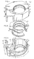
- Figures 4 and 5 a perspective plan view and a bottom view respectively of a volute mould wall of the pump housing of Figure 1,
- Figure 6 a fragmentary, perspective plan view of a suction mouth mould wall of a pump housing of Fig. 1,
- Figure 7 on an enlarged scale tie means for interconnecting mould wall parts in the direction of arrow VII in Figure 4, and
- Figure 8 a perspective view of a suction casing mould wall of a pump housing of Figure 1.
- The
pump station 1 of Figures 1 and 2 has aconcrete substructure 2 comprising two identical pump housings 3 for pumps 4. - This
pump station 1, for example of a draining mill, comprises pumps 4 of large dimensions having a high yield with a low lift. Each pump 4 has a pump housing 3 comprising a suction casing 5, a suction mouth 6, a volute 7 and aneffluent channel 8. A rotating impeller 9 is mounted in the pump housing by means of abearing 10. The impeller 9 is driven by amotor 12 viadriving gear 11. - In the manufacture of the pump housing 3, at least the volute 7, but preferably the suction mouth 6 and the suction casing 5 as well, are prefabricated in parts. Mould wall parts defining the space traversed by the fluid and serving, in addition, as lost casing elements are prefabricated first and are then assembled and mounted in place. Thereupon they are embedded in the
concrete 13 of thesubstructure 2, after ensuring that reinforcingelements 14 of the mould walls are connected with reinforcingelements 15 of theremaining substructure 2. - The following mould wall parts are shown:
- - a
volute mould wall 16 in Figures 4 and 5, - - a
suction mouth wall 17 in Figure 6, and - - a suction
casing mould wall 18 in Figure 8. - The
volute mould wall 16 has internally the shape of a volute, atongue 19 thereof being lined with ametal tongue element 20. The volute has furthermore an effluent piece 21. In a different embodiment other metal parts such as a foundation cover may be embedded. - The
volute mould wall 16 comprises twomould wall parts mould wall parts mould wall parts concrete 13 of thesubstructure 2 to be cast after thevolute mould wall 16 has been mounted. The suctionmouth mould wall 17 and the suctioncasing mould wall 18 each comprise twomould wall parts - The
mould wall parts steel brackets elements 14 of the mould wall parts and drawn towards one another by means of abolt 31 and anut 32. - The
volute mould wall 16, the suctionmouth mould wall 17 and the suctioncasing mould wall 18 are all assembled by means of such tie means. - Reinforcing
elements 14 projecting out of theconcrete 33 of themould wall parts 22 to 27 are connected with reinforcingelements 15 for theconcrete 13 of theconcrete substructure 2. Thereupon,concrete 13 is cast around themould wall parts 22 to 27 to complete theconcrete substructure 2. The location of the partitions in the mould walls is arbitrary both in a horizontal and in a vertical plane. Therefore, such partitions may be different from those shown herein.
Claims (13)
Priority Applications (1)
| Application Number | Priority Date | Filing Date | Title |
|---|---|---|---|
| AT83201090T ATE19678T1 (en) | 1982-08-12 | 1983-07-22 | PUMPING STATION AND MOLDING PARTS AND PROCESS FOR THEIR MANUFACTURE. |
Applications Claiming Priority (2)
| Application Number | Priority Date | Filing Date | Title |
|---|---|---|---|
| NL8203179A NL8203179A (en) | 1982-08-12 | 1982-08-12 | PUMP HOUSING, MOLDING OF A SHAPE FOR A PUMP HOUSING AND METHOD FOR MANUFACTURING A PUMP HOUSING. |
| NL8203179 | 1982-08-12 |
Publications (3)
| Publication Number | Publication Date |
|---|---|
| EP0101628A1 EP0101628A1 (en) | 1984-02-29 |
| EP0101628B1 true EP0101628B1 (en) | 1986-05-07 |
| EP0101628B2 EP0101628B2 (en) | 1996-03-13 |
Family
ID=19840133
Family Applications (1)
| Application Number | Title | Priority Date | Filing Date |
|---|---|---|---|
| EP83201090A Expired - Lifetime EP0101628B2 (en) | 1982-08-12 | 1983-07-22 | Pump station and method of manufacturing the same |
Country Status (7)
| Country | Link |
|---|---|
| US (2) | US4869643A (en) |
| EP (1) | EP0101628B2 (en) |
| JP (1) | JPS5949398A (en) |
| AT (1) | ATE19678T1 (en) |
| CA (1) | CA1221877A (en) |
| DE (1) | DE3363392D1 (en) |
| NL (1) | NL8203179A (en) |
Families Citing this family (9)
| Publication number | Priority date | Publication date | Assignee | Title |
|---|---|---|---|---|
| NL8203179A (en) * | 1982-08-12 | 1984-03-01 | Stork Pompen | PUMP HOUSING, MOLDING OF A SHAPE FOR A PUMP HOUSING AND METHOD FOR MANUFACTURING A PUMP HOUSING. |
| US5304034A (en) * | 1989-02-02 | 1994-04-19 | Stork Pompen B.V. | Method for constructing a pumping installation |
| NL193699B (en) * | 1989-02-02 | 2000-03-01 | Stork Pompen | Method for building up a pump installation and formwork used in the method. |
| DE19811598C2 (en) * | 1998-03-17 | 1999-12-23 | Siemens Ag | Cooling water pump and process for its manufacture |
| FR2793183B1 (en) * | 1999-05-03 | 2001-07-27 | Alstom | METHOD FOR MANUFACTURING A VOLUME PUMP BODY AND CORRESPONDING VOLUME PUMP BODY |
| DE10003517C2 (en) * | 2000-01-27 | 2001-11-22 | Siemens Ag | Operating building for a plant and method for operating an operating building |
| CN101358601B (en) * | 2007-08-02 | 2010-12-22 | 上海阿波罗机械股份有限公司 | Concrete spiral casing seawater circulation pump for nuclear plant |
| DE102009053879A1 (en) * | 2009-11-20 | 2011-05-26 | Voith Patent Gmbh | Tidal power plant and process for its preparation |
| SI3735529T1 (en) | 2019-03-13 | 2023-01-31 | Natel Energy, Inc. | Hydraulic turbine |
Family Cites Families (13)
| Publication number | Priority date | Publication date | Assignee | Title |
|---|---|---|---|---|
| US2687280A (en) * | 1954-08-24 | Pump-turbine | ||
| US841496A (en) * | 1906-02-20 | 1907-01-15 | William G Fargo | Penstock. |
| US1107591A (en) | 1913-05-17 | 1914-08-18 | Olier Centrifugal Pump And Machine Company D | Pump construction. |
| US1254417A (en) * | 1915-10-04 | 1918-01-22 | George A Leonard | Masonry wall construction. |
| US1608259A (en) * | 1917-07-24 | 1926-11-23 | Taylor Harvey Birchard | Hydraulic turbine |
| US1504737A (en) | 1921-07-01 | 1924-08-12 | Allis Chalmers Mfg Co | Hydraulic turbine |
| FR735684A (en) * | 1931-07-16 | 1932-11-14 | Sulzer Ag | Centrifugal machine with sheet metal volute casing |
| FR1038221A (en) * | 1951-06-08 | 1953-09-25 | Removable cylindrical silo-mold with prefabricated elements | |
| US3842562A (en) * | 1972-10-24 | 1974-10-22 | Larsen V Co | Interlocking precast concrete slabs |
| JPS5936719Y2 (en) * | 1980-05-26 | 1984-10-09 | 株式会社クボタ | Concrete casing of large vertical shaft pump |
| NL8203179A (en) * | 1982-08-12 | 1984-03-01 | Stork Pompen | PUMP HOUSING, MOLDING OF A SHAPE FOR A PUMP HOUSING AND METHOD FOR MANUFACTURING A PUMP HOUSING. |
| US4792282A (en) * | 1987-06-03 | 1988-12-20 | A. Janet Jordan | Liquid pump |
| JPH0781164A (en) * | 1993-06-30 | 1995-03-28 | Casio Comput Co Ltd | Electronic device with printer |
-
1982
- 1982-08-12 NL NL8203179A patent/NL8203179A/en not_active Application Discontinuation
-
1983
- 1983-07-22 AT AT83201090T patent/ATE19678T1/en not_active IP Right Cessation
- 1983-07-22 DE DE8383201090T patent/DE3363392D1/en not_active Expired
- 1983-07-22 EP EP83201090A patent/EP0101628B2/en not_active Expired - Lifetime
- 1983-07-29 US US06/518,676 patent/US4869643A/en not_active Expired - Lifetime
- 1983-08-09 CA CA000434187A patent/CA1221877A/en not_active Expired
- 1983-08-11 JP JP58147272A patent/JPS5949398A/en active Granted
-
1989
- 1989-08-16 US US07/394,478 patent/US5035574A/en not_active Expired - Lifetime
Also Published As
| Publication number | Publication date |
|---|---|
| DE3363392D1 (en) | 1986-06-12 |
| NL8203179A (en) | 1984-03-01 |
| US4869643A (en) | 1989-09-26 |
| EP0101628A1 (en) | 1984-02-29 |
| JPH0243040B2 (en) | 1990-09-26 |
| CA1221877A (en) | 1987-05-19 |
| JPS5949398A (en) | 1984-03-21 |
| EP0101628B2 (en) | 1996-03-13 |
| ATE19678T1 (en) | 1986-05-15 |
| US5035574A (en) | 1991-07-30 |
Similar Documents
| Publication | Publication Date | Title |
|---|---|---|
| EP0101628B2 (en) | Pump station and method of manufacturing the same | |
| US8628066B2 (en) | Cooling tower and method of constructing same | |
| RU2213273C2 (en) | Cooling water pump and method of its manufacture | |
| BRPI0711618A2 (en) | Method for the manufacture of a decanter and a decanter | |
| US5304034A (en) | Method for constructing a pumping installation | |
| US11988013B2 (en) | Wall assemblies, systems, and methods thereof | |
| JPH04103286U (en) | Suction stage of multistage circulation pump | |
| EP4390002A1 (en) | Concrete element, process for producing concrete element and formwork for casting concrete element | |
| EP0459034A1 (en) | Method for constructing a pumping installation and pumping installation manufactured according to the method | |
| JP2017002688A (en) | Bottom slab construction method and bottom slab structure | |
| JPS6310243B2 (en) | ||
| CN109469189B (en) | Assembled concrete prestress mould pressing box pump rainwater collecting tank and construction method thereof | |
| JP3530826B2 (en) | Simple rainwater pumping station | |
| JP2949341B1 (en) | Underwater girder construction method | |
| CN220469242U (en) | Module building Liang Moke and concrete beam | |
| FI75204B (en) | Pumping station | |
| CN213478778U (en) | Pumping system of irrigation and water conservancy irrigation pump station | |
| US6561754B1 (en) | Inlet structure for pump installations | |
| CN214423348U (en) | A throw stone mud jacking sand-free concrete small pile for road bed | |
| CN223256111U (en) | Water intake head box body component | |
| SU1013609A1 (en) | Device for underwater concreting | |
| JP2787114B2 (en) | Vertical pump with double spiral wound casing | |
| JP2903752B2 (en) | Submersible motor pump equipment | |
| JP2568930Y2 (en) | underwater pump | |
| CN118148082A (en) | Construction method of gold-coated silver concrete structure |
Legal Events
| Date | Code | Title | Description |
|---|---|---|---|
| PUAI | Public reference made under article 153(3) epc to a published international application that has entered the european phase |
Free format text: ORIGINAL CODE: 0009012 |
|
| 17P | Request for examination filed |
Effective date: 19831124 |
|
| AK | Designated contracting states |
Designated state(s): AT BE CH DE FR GB IT LI LU NL SE |
|
| GRAA | (expected) grant |
Free format text: ORIGINAL CODE: 0009210 |
|
| ITF | It: translation for a ep patent filed | ||
| AK | Designated contracting states |
Kind code of ref document: B1 Designated state(s): AT BE CH DE FR GB IT LI LU NL SE |
|
| REF | Corresponds to: |
Ref document number: 19678 Country of ref document: AT Date of ref document: 19860515 Kind code of ref document: T |
|
| REF | Corresponds to: |
Ref document number: 3363392 Country of ref document: DE Date of ref document: 19860612 |
|
| ET | Fr: translation filed | ||
| PG25 | Lapsed in a contracting state [announced via postgrant information from national office to epo] |
Ref country code: LU Free format text: LAPSE BECAUSE OF NON-PAYMENT OF DUE FEES Effective date: 19860731 |
|
| PLBI | Opposition filed |
Free format text: ORIGINAL CODE: 0009260 |
|
| 26 | Opposition filed |
Opponent name: KLEIN, SCHANZLIN & BECKER AG Effective date: 19870128 |
|
| NLR1 | Nl: opposition has been filed with the epo |
Opponent name: KLEIN, SCHANZLIN & BECKER AG |
|
| PLAB | Opposition data, opponent's data or that of the opponent's representative modified |
Free format text: ORIGINAL CODE: 0009299OPPO |
|
| R26 | Opposition filed (corrected) |
Opponent name: KSB AKTIENGESELLSCHAFT Effective date: 19870128 |
|
| NLXE | Nl: other communications concerning ep-patents (part 3 heading xe) |
Free format text: IN PAT.BUL.08/87,PAGE 1097:CORR.:KSB AKTIENGESELLSCHAFT |
|
| ITTA | It: last paid annual fee | ||
| EAL | Se: european patent in force in sweden |
Ref document number: 83201090.4 |
|
| ITF | It: translation for a ep patent filed | ||
| PUAH | Patent maintained in amended form |
Free format text: ORIGINAL CODE: 0009272 |
|
| STAA | Information on the status of an ep patent application or granted ep patent |
Free format text: STATUS: PATENT MAINTAINED AS AMENDED |
|
| 27A | Patent maintained in amended form |
Effective date: 19960313 |
|
| AK | Designated contracting states |
Kind code of ref document: B2 Designated state(s): AT BE CH DE FR GB IT LI LU NL SE |
|
| REG | Reference to a national code |
Ref country code: CH Ref legal event code: AEN Free format text: AUFRECHTERHALTUNG DES PATENTES IN GEAENDERTER FORM |
|
| NLR2 | Nl: decision of opposition | ||
| ET3 | Fr: translation filed ** decision concerning opposition | ||
| NLR3 | Nl: receipt of modified translations in the netherlands language after an opposition procedure | ||
| APAC | Appeal dossier modified |
Free format text: ORIGINAL CODE: EPIDOS NOAPO |
|
| APAC | Appeal dossier modified |
Free format text: ORIGINAL CODE: EPIDOS NOAPO |
|
| REG | Reference to a national code |
Ref country code: GB Ref legal event code: IF02 |
|
| PGFP | Annual fee paid to national office [announced via postgrant information from national office to epo] |
Ref country code: GB Payment date: 20020724 Year of fee payment: 20 |
|
| PGFP | Annual fee paid to national office [announced via postgrant information from national office to epo] |
Ref country code: SE Payment date: 20020726 Year of fee payment: 20 Ref country code: FR Payment date: 20020726 Year of fee payment: 20 Ref country code: AT Payment date: 20020726 Year of fee payment: 20 |
|
| PGFP | Annual fee paid to national office [announced via postgrant information from national office to epo] |
Ref country code: NL Payment date: 20020730 Year of fee payment: 20 |
|
| PGFP | Annual fee paid to national office [announced via postgrant information from national office to epo] |
Ref country code: DE Payment date: 20020731 Year of fee payment: 20 |
|
| PGFP | Annual fee paid to national office [announced via postgrant information from national office to epo] |
Ref country code: CH Payment date: 20020802 Year of fee payment: 20 |
|
| PGFP | Annual fee paid to national office [announced via postgrant information from national office to epo] |
Ref country code: BE Payment date: 20020919 Year of fee payment: 20 |
|
| PG25 | Lapsed in a contracting state [announced via postgrant information from national office to epo] |
Ref country code: LI Free format text: LAPSE BECAUSE OF EXPIRATION OF PROTECTION Effective date: 20030721 Ref country code: GB Free format text: LAPSE BECAUSE OF EXPIRATION OF PROTECTION Effective date: 20030721 Ref country code: CH Free format text: LAPSE BECAUSE OF EXPIRATION OF PROTECTION Effective date: 20030721 |
|
| PG25 | Lapsed in a contracting state [announced via postgrant information from national office to epo] |
Ref country code: NL Free format text: LAPSE BECAUSE OF EXPIRATION OF PROTECTION Effective date: 20030722 Ref country code: AT Free format text: LAPSE BECAUSE OF EXPIRATION OF PROTECTION Effective date: 20030722 |
|
| REG | Reference to a national code |
Ref country code: GB Ref legal event code: PE20 |
|
| REG | Reference to a national code |
Ref country code: CH Ref legal event code: PL |
|
| NLV7 | Nl: ceased due to reaching the maximum lifetime of a patent |
Effective date: 20030722 |
|
| EUG | Se: european patent has lapsed | ||
| APAH | Appeal reference modified |
Free format text: ORIGINAL CODE: EPIDOSCREFNO |