EP0101425B1 - Scherkraftlastzelle - Google Patents
Scherkraftlastzelle Download PDFInfo
- Publication number
- EP0101425B1 EP0101425B1 EP83850209A EP83850209A EP0101425B1 EP 0101425 B1 EP0101425 B1 EP 0101425B1 EP 83850209 A EP83850209 A EP 83850209A EP 83850209 A EP83850209 A EP 83850209A EP 0101425 B1 EP0101425 B1 EP 0101425B1
- Authority
- EP
- European Patent Office
- Prior art keywords
- recess
- shear
- load
- load cell
- section
- Prior art date
- Legal status (The legal status is an assumption and is not a legal conclusion. Google has not performed a legal analysis and makes no representation as to the accuracy of the status listed.)
- Expired
Links
- 230000007935 neutral effect Effects 0.000 claims description 29
- 210000004027 cell Anatomy 0.000 description 156
- 230000035945 sensitivity Effects 0.000 description 30
- 238000005452 bending Methods 0.000 description 28
- 230000002411 adverse Effects 0.000 description 27
- 238000005259 measurement Methods 0.000 description 17
- 238000010586 diagram Methods 0.000 description 14
- 239000002131 composite material Substances 0.000 description 8
- 238000005303 weighing Methods 0.000 description 8
- 230000000694 effects Effects 0.000 description 6
- 238000004519 manufacturing process Methods 0.000 description 6
- 230000006835 compression Effects 0.000 description 5
- 238000007906 compression Methods 0.000 description 5
- 239000000463 material Substances 0.000 description 5
- 238000013461 design Methods 0.000 description 4
- 238000002474 experimental method Methods 0.000 description 4
- 238000010276 construction Methods 0.000 description 3
- 230000007423 decrease Effects 0.000 description 3
- 238000011068 loading method Methods 0.000 description 3
- 238000012986 modification Methods 0.000 description 2
- 230000004048 modification Effects 0.000 description 2
- 238000013459 approach Methods 0.000 description 1
- 210000003850 cellular structure Anatomy 0.000 description 1
- 230000008859 change Effects 0.000 description 1
- 238000005553 drilling Methods 0.000 description 1
- 230000009467 reduction Effects 0.000 description 1
- 230000004044 response Effects 0.000 description 1
- 238000012360 testing method Methods 0.000 description 1
- 238000004078 waterproofing Methods 0.000 description 1
Images


Classifications
-
- G—PHYSICS
- G01—MEASURING; TESTING
- G01G—WEIGHING
- G01G3/00—Weighing apparatus characterised by the use of elastically-deformable members, e.g. spring balances
- G01G3/12—Weighing apparatus characterised by the use of elastically-deformable members, e.g. spring balances wherein the weighing element is in the form of a solid body stressed by pressure or tension during weighing
- G01G3/14—Weighing apparatus characterised by the use of elastically-deformable members, e.g. spring balances wherein the weighing element is in the form of a solid body stressed by pressure or tension during weighing measuring variations of electrical resistance
- G01G3/1402—Special supports with preselected places to mount the resistance strain gauges; Mounting of supports
- G01G3/1404—Special supports with preselected places to mount the resistance strain gauges; Mounting of supports combined with means to connect the strain gauges on electrical bridges
-
- G—PHYSICS
- G01—MEASURING; TESTING
- G01L—MEASURING FORCE, STRESS, TORQUE, WORK, MECHANICAL POWER, MECHANICAL EFFICIENCY, OR FLUID PRESSURE
- G01L1/00—Measuring force or stress, in general
- G01L1/20—Measuring force or stress, in general by measuring variations in ohmic resistance of solid materials or of electrically-conductive fluids; by making use of electrokinetic cells, i.e. liquid-containing cells wherein an electrical potential is produced or varied upon the application of stress
- G01L1/22—Measuring force or stress, in general by measuring variations in ohmic resistance of solid materials or of electrically-conductive fluids; by making use of electrokinetic cells, i.e. liquid-containing cells wherein an electrical potential is produced or varied upon the application of stress using resistance strain gauges
- G01L1/2206—Special supports with preselected places to mount the resistance strain gauges; Mounting of supports
- G01L1/2243—Special supports with preselected places to mount the resistance strain gauges; Mounting of supports the supports being parallelogram-shaped
Definitions
- This invention relates to a shear beam load cell and, more particularly, to a low-cost shear beam load cell with reduced sensitivity to adverse load conditions.
- Strain gage devices have proven effective for various industrial applications, such as for measuring axial load forces on equipment shafts, bending stresses on track rails for weighing railway cars, and the like.
- U.S. Patent Nos. 3,151,306 and 3,937,075 disclose strain gage devices adapted to measure axial load forces.
- strain gage device One particular type of strain gage device has now received significant recognition for industrial weighing applications.
- This device is commonly referred to as a shear beam load cell because it employs strain gages positioned to measure shear in a beam-shaped cell and connected to an appropriate electrical circuit for sensing the strain caused by the stresses of shear imposed on the beam, and thereby produce readings which are proportional to a load to be measured applied substantially perpendicular to the longitudinal direction of the beam.
- the shear beam load cell can measure both large and small loads, is accurate and can be used in many different industrial weighing environments.
- the shear beam load cell is also low-profile, small in size, and has low sensitivity to change in point-of-load application and to adverse side forces. Examples of shear-responsive strain gage weighing devices are disclosed in U.S. Patent Nos. 3,554,025; 3,734,216 and 3,448,424.
- shear beam load cells Despite the numerous advantages of shear beam load cells over other types of strain gage load cells and weighing devices, there remain problems with and disadvantages of the known shear beam load cells, particularly costs due to the components used in the load cell and the assembly of same, and accuracy in measuring the load applied to the shear beam load cell. Such problems are inherent to the design of the conventional shear beam load cell. For example, in order to properly measure the shear strain caused by the stresses in the beam of the conventional load cell, it has been necessary to place strain gages on opposite sides of the beam, each gage oriented essentially at 45 degrees to the longitudinal neutral axis of the beam.
- the positioning of the strain gages on the opposite sides of the load cell is critical to measurement accuracy because the load cell typically receives adverse twisting moments of torsion during the load application, thereby effecting proper measurement.
- the strain gages are precisely positioned on the opposite sides of the shear beam and have exactly the same strain sensitivity, the torsional effects are cancelled.
- precise perfect balancing is difficult to obtain.
- prior efforts to improve load measurement accuracy in the conventional shear beam cell design have resulted in higher costs. Reversely, prior efforts to lower the costs of a shear beam load cell have resulted in reduced load measurement accuracy.
- a recess is formed in the cantilevered beam free end in the load- measuring direction, with the force of the load being applied to a load bearing surface within the recess.
- the load bearing surface within the recess is located in proximity to the longitudinal neutral axis of the shear beam, thus minimizing the moment arm and the twisting moment of an adverse side force affecting the shear beam load cell.
- this load cell design has reduced load measurement inaccuracy that is due to imperfect positioning of the strain gages on opposite sides of the shear beam and which commonly occurs in manufacturing such load cells.
- the symmetrical I-shaped beam cross-section improves the functioning of the shear beam load cell.
- the shear strain is highest and relatively uniform in the web area. Therefore, the I-beam configuration is useful for the purpose of maximizing shear related stresses at a location where bending related stresses are relatively low. Shear strain measurement is thus maximized with the load cell being less sensitive to changes in the point of load application.
- precise positioning of the strain gages must be made in the diametrically-opposed holes of the symmetrical I-beam cross-section in order that they exactly cancel out the effects of twisting moments or torsion from adverse side forces or an off-centered load received by the load cell.
- the conventional shear beam load cells are still plagued by sensitivity to adverse torsion and twisting moments due to off-centered loads and/ or adverse side forces, and still require costly construction to contain or improve measurement accuracy, due to the components and assembly of same. That is, two sets of composite strain gage devices still have to be used, be precisely positioned on each side of the shear beam, and be of the same strain sensitivity to exactly cancel the effect on the other side of the beam. As noted previously, such precise, perfect positioning is difficult to obtain as a practical matter in mass production of these load cells. To the extent precise positioning is being attempted, the costs of manufacturing such shear beam load cells increases tremendously. Even with good positioning of the two opposing strain gage devices, other factors, such as temperature variations in the shear beam, continue to adversely affect proper cancellation.
- a new type of shear beam load cell is desired which maintains all of the advantages of a shear beam load cell over other weighing devices, yet which is lower in cost, simpler in construction and more economical to assemble, and improves the accuracy of the load measurement by minimizing significantly the sensitivity to torque and off-centered loads, temperature variations in the shear beam, and the like, over the conventional shear beam load cell.
- a specific object of this invention is to provide a shear beam load cell which does not require use of two separate strain gage sensing devices located on diametrically opposed sides of the shear beam to measure the shear strain corresponding to the load, thereby resulting in a fewer components, easier assembled, simpler and less costly shear beam load cell.
- Yet another object of this invention is to provide a shear beam load cell which is not affected by temperature variations between opposing sides of the shear beam on which two strain gage sensing devices are positioned, thereby resulting in a more accurate shear beam load cell having less sensitivity to such temperature variations.
- the shear beam load cell comprises: (1) a beam member, most frequently a cantilevered beam member, having-(a) a first deflectable weigh portion for receiving a load force to be measured, (b) a second relatively rigid support portion for supporting the beam member, and (c) recesses formed in opposing sides of the first weigh portion for defining an unsymmetrical I-shaped transverse cross-section, wherein the recesses have dimensions such that the bottom wall surface of one of the recesses is insensitive to torsion; and (2) strain gage sensing means positioned in the recess on the bottom wall surface insensitive to torsion for measuring the shear strain corresponding to the load force received by the first weigh portion.
- the strain gage sensing means positioned in the recess on the bottom wall surface insensitive to torsion comprises four strain gages mounted at 45° and 135° angles symmetrically to or along the longitudinal neutral axis of the first weigh portion, each gage respectively connected to the four different arms of a full Wheatstone bridge circuit for electrically measuring the principal tensile and compressive shear strains corresponding to the load force.
- only one strain gage sensing means is required in the one recess at the bottom surface insensitive to torsion for proper and accurate measurement of the shear strain corresponding to the load force.
- the recess with the bottom surface insensitive to torsion has a depth longer than the other recess. In yet another embodiment, the recess with the bottom surface insensitive to torsion has a height smaller than the other recess.
- the present invention achieves a low-cost shear beam load cell by using a single strain gage sensing device with yet a more accurate measurement of the load force by reducing sensitivity to adverse torque forces and off-centered loads.
- the shear beam load cell generally comprises a beam member and strain gage sensing means.
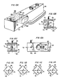
- the beam member is a cantilevered beam member 42 having a first free and deflectable weigh section 44 for receiving at one end thereof the force of a load to be measured, designated by the letter F (Fig. 10D).
- the beam member 42 also has a second section 46 for mounting beam member 42 to a foundation or other like securing surface, such as by high strength bolts 48.
- Elongated blind recesses 50 and 52 are formed in opposing sides of the cantilevered weigh section 44, as illustrated in Figs. 10A, 10B, 10C and 10D.
- the recesses 50 and 52 have dimensions for defining an unsymmetrical I-shaped transverse cross-section such that the bottom wall surface of one of the recesses is made insensitive to torsion.
- bottom surface insensitive to torsion is used herein, including the claims, to mean that a strain gage sensing means mounted on that bottom surface of the recess will be insensitive to strain measured by it that is caused by stresses associated with torsional forces.
- the recesses 50 and 52 are formed along the length of the weigh section 44 of beam member 42 at a location between the mounting section 46 and the point on the weight section 44 at which the load F is applied.
- the load measuring direction generally extends substantially perpendicular to the longitudinal axis 54 of the beam weigh section 44.
- the unsymmetrical I-shaped cross-section formed by the recesses 50 and 52 generally defines a flat web 56 vertically disposed between the recesses and having side walls forming bottom surfaces 58 and 60, respectively, of the recesses 50 and 52.
- the flat web 56 is in a plane substantially parallel to the longitudinal neutral axis 54 of the weigh section 44 and substantially parallel to the load F applied to the weigh section 44.
- a hole 62 is provided at the forward end of the weigh section 44 in the load measuring direction for receiving a load force therein.
- the unsymmetrical I-shaped transverse cross-section is configured, as best seen in Figs. 10B and 14A, such that the recess 52 is formed with the bottom surface 60 insensitive to torsion by having a depth a 2 longer than the depth a 1 of the other recess 50.
- the unsymmetrical I-shaped transverse cross-section is configured, as best seen in Figs. 10C and 14B, such that the recess 52 with the bottom surface insensitive to torsion has a height h 2 shorter than the height h 1 of the other recess 50.
- the load cell of this invention further comprises a strain gage sensing means positioned in the recess on the bottom wall surface insensitive to torsion for measuring the shear strain corresponding to the load F.
- the strain gage sensing means comprises a composite strain gage device that need be positioned in only the one recess on the bottom wall surface which is insensitive to torsion for properly and accurately measuring the shear strains corresponding to the magnitude of the load F applied to the load cell.
- the strain gage sensing means comprises a single composite strain gage device 64 mounted on the bottom wall surface 60 of the recess 52.
- the strain gage device comprises four strain gages 66, 68, 70, and 72 positioned on surface 60 at 45° and 135° angles symmetrically to the longitudinal neutral axis 54 of the weigh section 44. These gages are electrically connected together in the four arms of a full Wheatstone bridge circuit for measuring the principal shear strains caused by the stresses associated with the load F applied to the weigh section 44 of beam member 42.
- the connection of the four strain gages in the Wheatstone bridge circuit is illustrated in Figs. 11A through 11 D.
- Figs. 11A-11D also indicate the compressive and tensile strain measured by strain gages 66, 68, 70, and 72 in response to a load F (Fig. 11 A), an axial force f A (Fig. 11B), a side force f s (Fig. 11C), and a twisting moment m T (Fig. 11 D).
- the single strain gage device 64 provided in recess 52 on bottom wall surface 60 which is made insensitive to torsion requires no cancellation of those strains due to the stresses associated with torsion, i.e., twisting moment M T or an off-centered load F,, as in the prior art shear beam load cell, because the strain measured by the strain gages of device 64 is zero.
- This invention thus provides a new type of shear beam load cell which is not only low in manufacturing cost but one which also has significantly reduced sensitivity to adverse torsion conditions. To appreciate the significance of this new type of shear beam load cell over the conventional load cells, reference is again made to the prior art load cell depicted in Figs. 1A-1C.
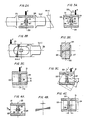
- the prior art shear beam load cell of Figs. 1A-1C employs a beam member 20 having a cantilevered beam end 21 and a mounting end 22.
- Identically dimensioned recesses 23 and 24 are provided on diametrically opposite sides of cantilevered beam end 21 for forming a symmetrical I-shaped cross-section, as best seen in Fig. 1 B, between the securing end 22 and a load receiving hole 25 in which the force of a load F is applied.
- the recesses 23 and 24 there are respectively mounted two composite strain gage devices 26 and 27.
- the devices 26 and 27 also respectively comprise at least two strain gages 28, 29 and 30, 31 oriented at 45° and 135° angles symmetrically to the longitudinal neutral axis 32 of the cantilevered beam member 20, as illustrated in Figs. 1C and 6B.
- the pairs of strain gages 28, 29, and 30,31, on the opposing sides of the symmetrical I-shaped beam cross-section are then electrically connected together in the four arms of a full Wheatstone bridge circuit as illustrated in Figs. 7A-7D for measuring the principal shear strains due to the stresses associated with the load F applied to the weigh end 21.
- Figs. 7A-7D also indicate the compressive and tensile strains measured by the strain gages 28, 29, 30, and 31 caused by stresses associated with to a force F (Fig. 7A), an axial force f A (Fig. 7B), a side force f s (Fig. 7C), and a twisting moment M T (Fig. 7D).
- Fig. 2A shows the shear stresses (s.s) and bending stresses (b.s.) distributed, along the symmetrical I-beam cross-section, wherein the shear stresses are highest in the web section of the I-beam cross-section and the bending stresses are theoretically zero at the longitudinal neutral axis along the web of the I-beam cross-section where the strain gages are mounted.
- the stresses on a shear beam load cell are not limited to those of pure load which is to be measured. There is most generally stresses caused by torsion and adverse forces, such as from an off-centered load F, illustrated in Fig. 3A, a side force f s illustrated in Fig. 4A, and/or a twisting moment M T illustrated in Fig. 5A.
- the additional compressive and tensile strain due to stresses along the symmetrical I-shaped cross-section associated with such adverse forces and torsion on the I-beam cross-section are respectively shown in Figs. 3B, 4B, and 5B.
- the I-beam cross-section was significant to reduce sensitivity to adverse side forces because the strain gages 27-31 are mounted on opposite sides of the web 34 close to the neutral plane of the beam in the center of the web of the symmetrical I-beam cross-section as seen in Figs. 3A, 4A, and 5A.
- Figs. 6A and 6B illustrate the load cell having a symmetrical I-beam cross section and strain gage devices 26 and 27 in the identically-dimensioned recesses 23 and 24 on opposite sides of the web with a pure load F, an axial force f A , a side force f s , and a twisting moment M T applied to the beam member 20.
- Fig. 6A and 6B illustrate the load cell having a symmetrical I-beam cross section and strain gage devices 26 and 27 in the identically-dimensioned recesses 23 and 24 on opposite sides of the web with a pure load F, an axial force f A , a side force f s , and a twisting moment M T applied to the beam member 20.
- FIG. 6B shows the positioning of the strain gages 28-31 with strain gages 28 and 29 shown on one side of the web in recess 23 at 45° and 135° angles to the longitudinal neutral axis of the cantilevered end 21 and the comparable component of strain gages 30 and 31 in the opposite recess 24 formed at 45° and 135° angles to the longitudinal neutral axis of the cantilevered end 21.
- the two pairs of strain gages 28, 29, and 30, 31, respectively are mounted in the recesses symmetrically relative to each other on opposite sides of the beam in such a way that the two strain gages in each pair 28, 29, and 30, 31, respectively, are affected by the deformations of the beam material in two mutually perpendicular directions forming an angle at 45° to the longitudinal axis of the beam.
- the two strain gages 28 and 31 are affected by compression or negative tension, whereas the two other strain gages 29 and 30 are affected by tension in the beam material.
- the strain gages 28-31 must then be electrically connected together in the four branches of the Wheatstone bridge circuit as shown in Figs. 7A-7D.
- the bridge has one diagonal connected to a voltage source and its other diagonal connected to a voltage measuring instrument 35.
- the two gages 29 and 30 affected by tension (+) are connected in two opposite branches of the bridge, whereas the two gages 28 and 31 affected by compression or negative tension (-) are connected in the other opposite branches of the bridge.
- R equals the resistance of the strain gages 28, 29, 30, and 31, which resistances R are conventionally made equal
- Ar represents the increase in resistance in the respective strain gages associated with a stress measurement, then the following formula applies: and. when then
- the shear strains associated with a load F can be measured but only with the pair of strain gage devices 26 and 27 having the same strain sensitivity and precisely and symmetrically arranged on opposite sides of the web of the symmetrical I-shaped cross-section to exactly cancel the effects of the strain due to adverse stresses.
- Such exact positioning of the strain gages 28-31 symmetrically in both recesses 23 and 24 on the opposite sides of the web 34 is difficult to obtain as a practical matter in mass producing such load cells. If a precise mounting of the strain gages 28-31 is provided, then there are generally high costs in manufacturing the load cells. Even with good positioning of the strain gages, temperature variations on opposite sides of the web and in the load cell continue to adversely affect proper cancellation.
- Fig. 9B The compressive strain measured by the gages 37-40 when an axial force f A is applied to the load cell is depicted in Fig. 9B. It can be seen that the compressive strain is cancelled by the circuit. Similarly, as shown in Fig. 9C, the compressive strain caused by stresses associated with a side force f s are cancelled by the Wheatstone bridge circuit. However, as shown in Fig. 9D, the compressive and tensile strain due to shear stresses associated with a twisting moment M T , or torsion, are not cancelled by the Wheatstone bridge circuit and instead a signal output is produced.
- this shear beam load cell configuration of Figs. 8A and 8B has a high sensitivity to strain associated with torsion or a twisting moment M T which affects the accurate measurement of the load F applied to the shear beam load cell.
- M T twisting moment
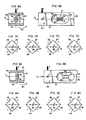
- a single composite strain gage device 64 is mounted on the bottom wall surface 60 of the recess 52, as best seen in Figs. 10B and 10C.
- the four strain gages 66, 68, 70, and 72 of device 64 are electrically connected together in the four arms of a full Wheatstone bridge circuit, as best seen in Figs. 11A-11D.
- a single strain gage sensing device 64 positioned on surface 60 could accurately measure the shear strain corresponding to the load F applied to the cantilevered beam member 42 without significant sensitivity to strain associated with a twisting moment and an adverse side force.
- the neutral axis of torsion and centroidal axis do not coincide with the center line running through the web of an unsymmetrical I-beam cross-section.
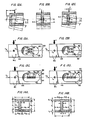
- Figs. 12A, 12B, and 12C a U-shaped unsymmetrical channel is depicted with the centroid (C.) for the channel cross-section located at a point between the U-shaped channel and the shear center (S.C.) located at a point to the left of the U-shaped channel.
- the shear center is the point through which the plane of loading must pass to get simple bending without torsion. If a force (f) is applied at a distance (e) away from the shear center along the plane containing the centroid, there is both a component of bending deflection as well as rotation of the U-shaped channel.
- FIGs. 12B and 12C an unsymmetrical I-shaped cross-section is depicted where the centroid is located along a plane substantially coinciding to the one surface of the web of the I-shaped cross-section, the shear center being located leftwardly of the centroid. If a force (f) is applied along the plane containing the shear center, there is simple bending deflection as shown in Fig. 12B. If a force (f) is applied at a distance (e) away from the shear center along the plane containing the centroid, there is both a component of bending deflection as well as rotation of the unsymmetrical I-beam cross-section, as illustrated in Fig. 12C.
- Example 1 it can be seen from Example 1 that by varying the ratio in the heights of the two recesses 50 and 52 in the above-noted manner, and as depicted in Fig. 14B, the plane containing the centroid of the unsymmetrical I-beam cross-section can substantially coincide to the bottom wall surface 60 of recess 52.
- the depth a 2 of the recess 52 would be greater than the depth a 1 of recess 50 and increased in the manner described above in order for the plane containing the centroid of the unsymmetrical I-beam section to coincide to the bottom surface 60 of the recess 52.
- Example 3 It can be seen from Example 3 that the distance (e) from the shear center (S.C.) to the centroid (C.) located on the bottom wall surface 60 of the recess 52 is significantly greater than in Examples 1 and 2. Thus, the dimensional proportions set forth in Example 3 are not as practical as those set forth in Examples 1 and 2 because of increased stresses due to greater torsion when applying the load F.
- the recesses 50 and 52 can have predetermined dimensions such that the bottom wall surface 60 in recess 52 of the shear beam load cell coincides substantially to the plane containing the centroids along the longitudinal direction of the unsymmetrical I-beam cross-section.
- recess surface 60 should be insensitive to torsion and side forces because of the neutral axis of torsion and the principal plane of bending falling within the plane containing the centroids.
- the recess 52 has a depth longer than the depth of recess 50. In another embodiment, the recess 52 has a height shorter than the height of recess 50.
- a single composite strain gage device 64 comprising strain gages 66, 68, 70, and 72 is mounted on wall surface 60, as shown in Fig. 10D and described earlier, with the gages then connected together in the arms of a full Wheatstone bridge circuit.
- the two gages 66 and 72, affected by tension (+), are connected in opposite branches of the bridge, whereas the gages 68 and 70, affected by compression or negative tension (-), are connected in the other opposite branches of the bridge.
- the shear beam load cell in accordance with the invention, thus more accurately measures the shear strain associated with the load F to be measured.
- the transverse moment sensitivity was less than 0.01 percent per 1/8th inch in transverse point-of-load movement when an off-centered load was applied. This is in contrast to transverse moment sensitivity typically between 0.02 and 0.03 percent per 1/8th inch transverse point-of-load movement in a conventional shear beam load cell (assuming accurate positioning of the pairs of strain gage sensing devices symmetrically on opposite sides of the web of the symmetrical I-beam cross-section).
- strain gages 66, 68, 70, and 72 of the strain gage device 64 in recess 52 are illustrated in Fig. 10D
- other arrangements of the strain gages can be provided as illustrated in Figs. 13A, 13B, 13C and 13D.
- strain gages 66, 68, 70, and 72 remain in symmetry above and below the longitudinal neutral axis 54, but are placed in different 45° and 135° angle orientation in comparison to the arrangement shown in Fig. 10B.
- the pairs of gages 66, 72 and 68, 70 are connected in the opposite branches of the full Wheatstone bridge to achieve the same results as shown in Figs. 11A-11B.
- FIGS. 13A and 13D show the strain gages 66, 68, 70, and 72 mounted along the longitudinal neutral axis 54 but are again connected together in the arms of a full Wheatstone bridge circuit in such a manner to provide the same measurements as depicted in Figs. 11A-11D.
- the embodiment of the load cell of Fig. 10A was formed with elongated blind recesses for defining the unsymmetrical I-beam transverse cross-section on which the strain gage device 64 was mounted.
- the strain gage device 64 was mounted.
- the centroidal axis and the neutral axis of torsion would fall in a plane coinciding to the plane of the bottom wall surface 60 of the recess 52.
- the load F was also applied at the end of the cantilevered beam section 42, as illustrated in Fig. 10D, at a distance sufficiently away from the recesses 50 and 52 so that there would be no spurious stress concentrations at the edges of the I-beam cross-section resulting from proximity of the load F.
- a single composite strain gage device 64 is mounted again only in the recess 52 which is to have a bottom surface 60 made insensitive to torsion.
- the strain gages 66, 68, 70, and 72 must now be mounted into a smaller circular recess, the bottom wall surface of the recess may not coincide exactly with a plane that is insensitive to torsion. That is, the dimensions of the unsymmetrical I-shaped cross-section taken along sectional lines a ⁇ e shown in Fig. 15B will vary, and a true continuous uniformly-dimensional I-beam section does not exist as in an elongated recess.
- dimensions of the recesses 50 and 52 can first be determined in accordance with the formulas described earlier with the gages 66, 68, 70, and 72 of the gage device 64 mounted on bottom wall surface 60 of recess 52 and connected together in the arms of the Wheatstone bridge circuit. Measurement is then made to determine if the sensitivity of the gages to the stresses associated with torsion or a twisting moment and a side force are zero. If not, adjustments are necessary and changes are made in the dimensions of the unsymmetrical I-beam cross-section to shift the neutral surface to the desired position. For example, additional material can be removed from the web 56 at the bottom surface 60 of recess 52 opposite to recess 50.
- the load cell is again tested to determine if the readings of the gages become insensitive to torsion from twisting moments and bending from side forces.
- additional material could be removed from the flanges 74 in the recess 50 opposite the recess 52 in which the gages are mounted to accommodate the same adjustments; this would be a preferable approach because the gages can remain mounted in recess 52.
- shear beam load cells of this exact configuration can be mass produced using numerical control or other automated drilling machinery and the like.
- shear beam load cell in accordance with the invention.
- the shear beam load cell could take the form of a device for weighing railway cars comprising a rail supported at both ends, with strain gages positioned in unsymmetrical recesses in the rail and located at a distance between the end supports. This would be in contrast to a cantilevered beam member having a free end deflectable weigh section with a section securely mounted to a foundation by bolts or the like.
- the shear beam load cell could take the form of a double shear beam as disclosed by the inventor in U.S. Patent No. 4,037,469.
- the shear beam load cell can be provided with a hole at the forward end thereof in the load measuring direction with a load application force receiving surface in the hole, as further disclosed by the inventor in U.S. Patent No. 3,960,228.
- shear beam load cell in accordance with the invention, can be used in all of the typical applications and loading methods used in the industry.
- Such loading methods and applications include a shear beam load cell having a suspended load assembly, a load button, or a load bearing support member to which a load is applied with the support member being positioned in the load hole of the cell.
Landscapes
- Physics & Mathematics (AREA)
- General Physics & Mathematics (AREA)
- Measurement Of Force In General (AREA)
Claims (23)


Applications Claiming Priority (2)
| Application Number | Priority Date | Filing Date | Title |
|---|---|---|---|
| US06/406,550 US4459863A (en) | 1982-08-09 | 1982-08-09 | Shear beam load cell |
| US406550 | 2003-04-03 |
Publications (3)
| Publication Number | Publication Date |
|---|---|
| EP0101425A2 EP0101425A2 (de) | 1984-02-22 |
| EP0101425A3 EP0101425A3 (en) | 1985-04-24 |
| EP0101425B1 true EP0101425B1 (de) | 1988-12-14 |
Family
ID=23608459
Family Applications (1)
| Application Number | Title | Priority Date | Filing Date |
|---|---|---|---|
| EP83850209A Expired EP0101425B1 (de) | 1982-08-09 | 1983-08-04 | Scherkraftlastzelle |
Country Status (3)
| Country | Link |
|---|---|
| US (1) | US4459863A (de) |
| EP (1) | EP0101425B1 (de) |
| DE (1) | DE3378696D1 (de) |
Families Citing this family (27)
| Publication number | Priority date | Publication date | Assignee | Title |
|---|---|---|---|---|
| US4657097A (en) * | 1984-02-13 | 1987-04-14 | Reliance Electric Company | Load cell |
| US4558756A (en) * | 1984-04-23 | 1985-12-17 | Toledo Transducers, Inc. | Cantilever support beam assembly for a load cell and the like |
| US4666003A (en) * | 1985-09-17 | 1987-05-19 | Stress-Tek, Inc. | On-board load cell |
| US4702329A (en) * | 1986-03-04 | 1987-10-27 | Click Billy J | Load cell |
| US4694921A (en) * | 1986-10-20 | 1987-09-22 | Butler Manufacturing Company | Shear beam weigh axle transducer |
| US4775018A (en) * | 1987-02-03 | 1988-10-04 | Kroll William P | Load cell assembly |
| SE459212C (sv) * | 1988-03-10 | 1994-02-07 | Stefan Valdemarsson | Anordning för mätning och/eller registrering av mekaniska krafter |
| DE4034629A1 (de) | 1990-10-31 | 1992-05-07 | Philips Patentverwaltung | Scheibenfoermiger messwertaufnehmer fuer eine waegezelle |
| US5220971A (en) * | 1991-09-24 | 1993-06-22 | Sensortronics | Shear beam, single-point load cell |
| US5831221A (en) * | 1994-10-13 | 1998-11-03 | Future Sysems, Inc. | Caster mounted weighing system |
| US5823278A (en) * | 1994-10-13 | 1998-10-20 | Future Systems, Inc. | Caster mounted weighing system |
| EP0773434B1 (de) * | 1995-10-10 | 2002-08-07 | Hottinger Baldwin Messtechnik Gmbh | Kraftaufnehmer |
| GB9912486D0 (en) * | 1999-05-29 | 1999-07-28 | Taylor Egbert H & Co Ltd | Weighing device |
| EP1189046A3 (de) * | 2000-09-19 | 2003-08-06 | Siemens Aktiengesellschaft | Biege- und torsionsmomentunempfindlicher Querkraftsensor |
| US7100458B2 (en) * | 2003-05-22 | 2006-09-05 | Crane Nuclear, Inc. | Flexure system for strain-based instruments |
| DE102004047508B3 (de) * | 2004-09-28 | 2006-04-20 | Hottinger Baldwin Messtechnik Gmbh | Messgrößenaufnehmer |
| DE102005057473B4 (de) * | 2005-11-30 | 2012-09-20 | Schenk Process Gmbh | Verfahren und Vorrichtung zur Erfassung von auf eine Schiene einwirkenden Kräften |
| US8276466B2 (en) * | 2010-03-31 | 2012-10-02 | Kulite Semiconductor Products, Inc. | Two or three-axis shear load cell |
| CN104350366A (zh) * | 2012-05-25 | 2015-02-11 | 株式会社日立制作所 | 力学量测量装置 |
| US9709436B2 (en) * | 2013-03-15 | 2017-07-18 | Illinois Tool Works Inc. | Load cell that is symmetrical about a central vertical axis |
| DE102013012507B4 (de) * | 2013-07-26 | 2016-06-16 | Hottinger Baldwin Messtechnik Gmbh | Stabförmiger Kraftaufnehmer mit vereinfachtem Abgleich |
| US9874485B2 (en) * | 2013-09-26 | 2018-01-23 | Fisher Controls International Llc | Valve stem connector with integrated stem force measurement |
| RU179728U1 (ru) * | 2017-12-27 | 2018-05-23 | Алексей Викторович Курбаков | Датчик усилия тензометрический |
| CN110987132B (zh) * | 2019-12-27 | 2025-04-22 | 陕西四维衡器科技有限公司 | 双输出剪切梁式称重传感器及载荷位置检测方法 |
| CN112924009A (zh) * | 2021-01-18 | 2021-06-08 | 梅特勒-托利多(常州)测量技术有限公司 | 剪切梁称重传感器、称重系统以及称重传感方法 |
| CN113340394B (zh) * | 2021-04-27 | 2022-06-07 | 湖北天瑞电子股份有限公司 | 一种整体剪切梁式传感器 |
| CN113324689B (zh) * | 2021-05-25 | 2022-08-26 | 重庆大学 | 剪切侧向力实时测量装置及测量方法 |
Citations (9)
| Publication number | Priority date | Publication date | Assignee | Title |
|---|---|---|---|---|
| US3151306A (en) * | 1961-08-25 | 1964-09-29 | Baldwin Lima Hamilton Corp | Electrical strain transducer |
| US3448424A (en) * | 1967-01-17 | 1969-06-03 | Blh Electronics | Shear-responsive force transducers |
| US3554025A (en) * | 1967-02-08 | 1971-01-12 | Bofors Ab | Force measuring device |
| US3734216A (en) * | 1970-09-21 | 1973-05-22 | Conrail Ab | Weighing device |
| US3937075A (en) * | 1973-10-16 | 1976-02-10 | U.S. Philips Corporation | Transducer comprising strain gauges |
| US3960228A (en) * | 1974-05-31 | 1976-06-01 | Transearch Ab | Shear beam load cell |
| US4037469A (en) * | 1975-08-11 | 1977-07-26 | Transrail Ab | Force measuring apparatus |
| US4237727A (en) * | 1979-04-30 | 1980-12-09 | Hottinger Baldwin Measurements, Inc. | Mechanical moment sensitivity compensation in shear beam transducers |
| US4282748A (en) * | 1979-06-27 | 1981-08-11 | Hottinger Baldwin Measurements, Inc. | Mechanical moment sensitivity compensation in shear beam transducers |
Family Cites Families (6)
| Publication number | Priority date | Publication date | Assignee | Title |
|---|---|---|---|---|
| GB903941A (en) * | 1959-07-14 | 1962-08-22 | Vyzk A Zkusebni Letecky Ustav | Improvements in or relating to strain measuring devices |
| FR1358105A (fr) * | 1963-05-28 | 1964-04-10 | Philips Nv | Organe de mesure pour un dynamomètre |
| US3520182A (en) * | 1967-06-05 | 1970-07-14 | Kelk Ltd George | Load cells |
| SE354119B (de) * | 1970-06-01 | 1973-02-26 | Bofors Ab | |
| US3949603A (en) * | 1974-07-01 | 1976-04-13 | Hottinger Baldwin Measurements | Strain gage transducer |
| US4364279A (en) * | 1980-12-31 | 1982-12-21 | Allegany Technology, Inc. | Shear beam load cell system |
-
1982
- 1982-08-09 US US06/406,550 patent/US4459863A/en not_active Expired - Lifetime
-
1983
- 1983-08-04 EP EP83850209A patent/EP0101425B1/de not_active Expired
- 1983-08-04 DE DE8383850209T patent/DE3378696D1/de not_active Expired
Patent Citations (9)
| Publication number | Priority date | Publication date | Assignee | Title |
|---|---|---|---|---|
| US3151306A (en) * | 1961-08-25 | 1964-09-29 | Baldwin Lima Hamilton Corp | Electrical strain transducer |
| US3448424A (en) * | 1967-01-17 | 1969-06-03 | Blh Electronics | Shear-responsive force transducers |
| US3554025A (en) * | 1967-02-08 | 1971-01-12 | Bofors Ab | Force measuring device |
| US3734216A (en) * | 1970-09-21 | 1973-05-22 | Conrail Ab | Weighing device |
| US3937075A (en) * | 1973-10-16 | 1976-02-10 | U.S. Philips Corporation | Transducer comprising strain gauges |
| US3960228A (en) * | 1974-05-31 | 1976-06-01 | Transearch Ab | Shear beam load cell |
| US4037469A (en) * | 1975-08-11 | 1977-07-26 | Transrail Ab | Force measuring apparatus |
| US4237727A (en) * | 1979-04-30 | 1980-12-09 | Hottinger Baldwin Measurements, Inc. | Mechanical moment sensitivity compensation in shear beam transducers |
| US4282748A (en) * | 1979-06-27 | 1981-08-11 | Hottinger Baldwin Measurements, Inc. | Mechanical moment sensitivity compensation in shear beam transducers |
Also Published As
| Publication number | Publication date |
|---|---|
| EP0101425A2 (de) | 1984-02-22 |
| EP0101425A3 (en) | 1985-04-24 |
| DE3378696D1 (en) | 1989-01-19 |
| US4459863A (en) | 1984-07-17 |
Similar Documents
| Publication | Publication Date | Title |
|---|---|---|
| EP0101425B1 (de) | Scherkraftlastzelle | |
| CA1047055A (en) | Constant moment weigh scale with floating flexure beam | |
| US4128001A (en) | Parallel beam load cell insensitive to point of application of load | |
| US3927560A (en) | Moment desensitization of load cells | |
| US4064744A (en) | Strain sensorextensiometer | |
| US3376537A (en) | Shear strain load cell | |
| AU2013361804B2 (en) | Load cell with inclination compensation | |
| US3949603A (en) | Strain gage transducer | |
| CN106404130B (zh) | 称重传感器组件及称重方法 | |
| US5925832A (en) | Torsional sensing load cell | |
| US4454769A (en) | Radial force measuring cell | |
| US4558756A (en) | Cantilever support beam assembly for a load cell and the like | |
| US4506746A (en) | Gaged plate transducer weighing apparatus | |
| US11092477B2 (en) | Planar load cell assembly | |
| US4385527A (en) | Aircraft weighing systems | |
| US20220011150A1 (en) | Planar load cell assembly | |
| AU626680B2 (en) | Strain gauge weighing device | |
| US4522066A (en) | Temperature-compensated extensometer | |
| EP0114530B1 (de) | Waage mit einer Kraftmesszelle | |
| US5295399A (en) | Force moment sensor | |
| US3772912A (en) | Load cell comprising two mutually movable members in a measuring direction | |
| US4580645A (en) | Constant moment weigh scale with misalignment compensator | |
| RU2145700C1 (ru) | Грузоприемное устройство весов | |
| USRE32002E (en) | Constant moment weigh scale with floating flexure beam | |
| EP3990874A1 (de) | Planare lastzellenanordnung |
Legal Events
| Date | Code | Title | Description |
|---|---|---|---|
| PUAI | Public reference made under article 153(3) epc to a published international application that has entered the european phase |
Free format text: ORIGINAL CODE: 0009012 |
|
| AK | Designated contracting states |
Designated state(s): CH DE FR GB LI NL SE |
|
| PUAL | Search report despatched |
Free format text: ORIGINAL CODE: 0009013 |
|
| AK | Designated contracting states |
Designated state(s): CH DE FR GB LI NL SE |
|
| 17P | Request for examination filed |
Effective date: 19850829 |
|
| 17Q | First examination report despatched |
Effective date: 19870506 |
|
| GRAA | (expected) grant |
Free format text: ORIGINAL CODE: 0009210 |
|
| AK | Designated contracting states |
Kind code of ref document: B1 Designated state(s): CH DE FR GB LI NL SE |
|
| PG25 | Lapsed in a contracting state [announced via postgrant information from national office to epo] |
Ref country code: NL Effective date: 19881214 Ref country code: LI Effective date: 19881214 Ref country code: FR Free format text: THE PATENT HAS BEEN ANNULLED BY A DECISION OF A NATIONAL AUTHORITY Effective date: 19881214 Ref country code: CH Effective date: 19881214 |
|
| REF | Corresponds to: |
Ref document number: 3378696 Country of ref document: DE Date of ref document: 19890119 |
|
| REG | Reference to a national code |
Ref country code: CH Ref legal event code: PL |
|
| EN | Fr: translation not filed | ||
| NLV1 | Nl: lapsed or annulled due to failure to fulfill the requirements of art. 29p and 29m of the patents act | ||
| PGFP | Annual fee paid to national office [announced via postgrant information from national office to epo] |
Ref country code: DE Payment date: 19890809 Year of fee payment: 7 |
|
| PGFP | Annual fee paid to national office [announced via postgrant information from national office to epo] |
Ref country code: GB Payment date: 19890831 Year of fee payment: 7 |
|
| PLBE | No opposition filed within time limit |
Free format text: ORIGINAL CODE: 0009261 |
|
| STAA | Information on the status of an ep patent application or granted ep patent |
Free format text: STATUS: NO OPPOSITION FILED WITHIN TIME LIMIT |
|
| 26N | No opposition filed | ||
| PG25 | Lapsed in a contracting state [announced via postgrant information from national office to epo] |
Ref country code: GB Effective date: 19900804 |
|
| GBPC | Gb: european patent ceased through non-payment of renewal fee | ||
| PG25 | Lapsed in a contracting state [announced via postgrant information from national office to epo] |
Ref country code: DE Effective date: 19910501 |
|
| PGFP | Annual fee paid to national office [announced via postgrant information from national office to epo] |
Ref country code: SE Payment date: 19910802 Year of fee payment: 9 |
|
| PG25 | Lapsed in a contracting state [announced via postgrant information from national office to epo] |
Ref country code: SE Effective date: 19920805 |
|
| EUG | Se: european patent has lapsed |
Ref document number: 83850209.4 Effective date: 19930307 |