EP0101346A2 - Hydraulisches Werkzeug - Google Patents
Hydraulisches Werkzeug Download PDFInfo
- Publication number
- EP0101346A2 EP0101346A2 EP83401453A EP83401453A EP0101346A2 EP 0101346 A2 EP0101346 A2 EP 0101346A2 EP 83401453 A EP83401453 A EP 83401453A EP 83401453 A EP83401453 A EP 83401453A EP 0101346 A2 EP0101346 A2 EP 0101346A2
- Authority
- EP
- European Patent Office
- Prior art keywords
- hydraulic
- chassis
- wheels
- pressure generator
- machine according
- Prior art date
- Legal status (The legal status is an assumption and is not a legal conclusion. Google has not performed a legal analysis and makes no representation as to the accuracy of the status listed.)
- Withdrawn
Links
- 238000006073 displacement reaction Methods 0.000 claims description 9
- 238000012423 maintenance Methods 0.000 abstract description 2
- 238000010586 diagram Methods 0.000 description 2
- 238000010276 construction Methods 0.000 description 1
- 230000009347 mechanical transmission Effects 0.000 description 1
Images


Classifications
-
- B—PERFORMING OPERATIONS; TRANSPORTING
- B60—VEHICLES IN GENERAL
- B60K—ARRANGEMENT OR MOUNTING OF PROPULSION UNITS OR OF TRANSMISSIONS IN VEHICLES; ARRANGEMENT OR MOUNTING OF PLURAL DIVERSE PRIME-MOVERS IN VEHICLES; AUXILIARY DRIVES FOR VEHICLES; INSTRUMENTATION OR DASHBOARDS FOR VEHICLES; ARRANGEMENTS IN CONNECTION WITH COOLING, AIR INTAKE, GAS EXHAUST OR FUEL SUPPLY OF PROPULSION UNITS IN VEHICLES
- B60K17/00—Arrangement or mounting of transmissions in vehicles
- B60K17/04—Arrangement or mounting of transmissions in vehicles characterised by arrangement, location or kind of gearing
- B60K17/14—Arrangement or mounting of transmissions in vehicles characterised by arrangement, location or kind of gearing the motor of fluid or electric gearing being disposed in, or adjacent to, traction wheel
-
- B—PERFORMING OPERATIONS; TRANSPORTING
- B62—LAND VEHICLES FOR TRAVELLING OTHERWISE THAN ON RAILS
- B62D—MOTOR VEHICLES; TRAILERS
- B62D53/00—Tractor-trailer combinations; Road trains
- B62D53/02—Tractor-trailer combinations; Road trains comprising a uniaxle tractor unit and a uniaxle trailer unit
Definitions
- the present invention relates to a hydraulic machine equipped with a hydraulic pressure generator group used to propel the machine and to supply hydraulic power to hydraulic tools.
- a hydraulic machine equipped with a hydraulic pressure generator group used to propel the machine and to supply hydraulic power to hydraulic tools.
- Such a machine is in particular intended for mobile railway maintenance sites.
- hydraulic tools such as: drills, screwdrivers, screwdrivers, chainsaws, impact wrenches. These hydraulic tools are then connected to a hydraulic pressure generator group which must generally be moved to monitor the site.
- Known generators are not very suitable for traveling.
- the present invention relates to a machine equipped with a hydraulic pressure generator group which is self-powered, the group serving both to propel the machine and to supply hydraulic power to the tools.
- This machine is provided with wheels driven by hydraulic motors which provide a significant torque which allows the easy crossing of obstacles.
- the machine is provided with a braking system which cooperates with the hydraulic motors so as to control the differences in the rotational speeds between the wheels (in the event of resistance on a wheel for example).
- the chassis of the machine allows the wheels to follow the movements of the ground although the hydraulic motors are fixedly mounted on this chassis.
- the machine equipped with a hydraulic pressure generator group, is essentially characterized in that this group is mounted on a wheeled vehicle and that at least two of the wheels of this vehicle are each driven .by a hydraulic motor powered by said pressure generator group.
- the machine comprises braking members acting independently on the wheels driven by said hydraulic motors.
- the motors are mounted on the chassis of the vehicle which consists of a half-chassis carried by two wheels and another half-chassis carried by two other wheels, these two half-chassis being coupled together. one to the other by a central articulation allowing the relative rotation of the two half-chassis around a vertical axis and a horizontal axis, hydraulic means controlling the relative orientation of the two half-chassis around the vertical axis .
- the machine comprises a group generally having hydraulic pressure 1 constituted by pumps 12, 13, 14 driven by a heat engine 11.
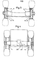
- This group 1 is mounted on a self-propelled vehicle comprising a chassis 2 carried by a train of front wheels 3 and by a train of rear wheels 4. These wheels can be coupled to railway wheels, coaxial, so as to allow rail- road.
- the chassis consists of a half-chassis 21 carried by the wheels 3 and a half-chassis 22 carried by the wheels 4. These half-chassis are coupled to each other by a central articulation 23.
- the half-frame 21 which will be called half-engine chassis carries group 1.
- the wheels 3 of the carrier half-chassis are directly driven by motors 5 which are each coupled to a wheel.
- the hub of each wheel is fixed on the output shaft of a motor 5 which is fixed to a flange of the half-chassis.
- the rear wheels 4, non-driving, are mounted by means of bearings on the half-chassis fuses 22.
- the central articulation 23 is a clevis articulation comprising a lever 231 joined so as to be able to pivot about a vertical axis to a fork 232 secured to the half-frame 21.
- This lever is joined by 233 with a horizontal axis at the allows articulation cylindrical / semi-chassis 22. This articulation / relative rotation of the two half-chassis around a vertical axis and around a horizontal axis by the axis 233.
- the end of the lever 231 is coupled to the rod of a steering cylinder 6, the cylinder of which is coupled by an articulation to the half-frame 21.
- the outputs and re-entries of the rod of this cylinder determine the relative orientation of the two half chassis 21 and 22.
- Brakes 7 are provided for braking the drive wheels 3 independently of one another. These brakes are of the jaw type, the jaws being maneuvered by hydraulic cylinders 71. By acting on one or the other of the brakes, it is possible to control the differences in rotation of the hydraulic motors.
- the hydraulic pressure generator group supplies the hydraulic motors 5 and connections 91 to which hydraulic tools can be connected. Furthermore, it supplies hydraulic power to the brake cylinders 71 and for the control of the steering cylinder 6.
- the pressure generator group 1 consists of a heat engine 11 driving a variable displacement pump 12 and constant displacement pumps 13, 14.
- the variable displacement pump 12 supplies the hydraulic motors 5 in parallel and d on the other hand of the fittings 91, the supply being controlled by a distributor 98 alternately towards the motors or the fittings.
- the steering control cylinder 6 is supplied by means of a manually controlled steering device 93 itself supplied by a constant displacement pump 13.
- This device 93 with manual control is operated by a steering wheel placed on the switchboard of the machine so that it can be maneuvered by the operator.
- This device 93 is mounted on a slide of the engine half-chassis so as to be able to slide linearly by acting on the flywheel. It is connected to the control lever of the variable displacement pump 12 by a mechanical transmission. In this way, by linearly moving the device 93 by the handwheel, the operator controls the flow rate of the pump 12.
- Each brake cylinder 71 can be supplied independently by the distributor 94 supplied by a pump 14.
- the constant displacement pump (s) 13, 14 supply fittings, not shown, to which hydraulic tools working at constant speed can be connected.
- the vehicle could include a system for changing the wheel spacing.
Landscapes
- Engineering & Computer Science (AREA)
- Chemical & Material Sciences (AREA)
- Combustion & Propulsion (AREA)
- Transportation (AREA)
- Mechanical Engineering (AREA)
- Motor Power Transmission Devices (AREA)
- Arrangement Or Mounting Of Propulsion Units For Vehicles (AREA)
- Control Of Fluid Gearings (AREA)
- Auxiliary Drives, Propulsion Controls, And Safety Devices (AREA)
Applications Claiming Priority (2)
| Application Number | Priority Date | Filing Date | Title |
|---|---|---|---|
| FR8212440A FR2530197A1 (fr) | 1982-07-16 | 1982-07-16 | Groupe hydraulique auto-propulse |
| FR8212440 | 1982-07-16 |
Publications (2)
| Publication Number | Publication Date |
|---|---|
| EP0101346A2 true EP0101346A2 (de) | 1984-02-22 |
| EP0101346A3 EP0101346A3 (de) | 1985-06-19 |
Family
ID=9276021
Family Applications (1)
| Application Number | Title | Priority Date | Filing Date |
|---|---|---|---|
| EP83401453A Withdrawn EP0101346A3 (de) | 1982-07-16 | 1983-07-13 | Hydraulisches Werkzeug |
Country Status (3)
| Country | Link |
|---|---|
| EP (1) | EP0101346A3 (de) |
| ES (1) | ES8500143A1 (de) |
| FR (1) | FR2530197A1 (de) |
Family Cites Families (3)
| Publication number | Priority date | Publication date | Assignee | Title |
|---|---|---|---|---|
| FR2336046A5 (fr) * | 1973-02-22 | 1977-07-15 | Braud & Faucheux | Dispositif d'articulation double pour engin tous terrains et engins equipes d'une telle articulation |
| US3910369A (en) * | 1974-04-12 | 1975-10-07 | Clark Equipment Co | Hydrostatic transmission system for articulated vehicle |
| FI60832C (fi) * | 1978-09-12 | 1982-04-13 | Orvo Kalevi Naamanka | Terraengfordon |
-
1982
- 1982-07-16 FR FR8212440A patent/FR2530197A1/fr not_active Withdrawn
-
1983
- 1983-07-13 EP EP83401453A patent/EP0101346A3/de not_active Withdrawn
- 1983-07-14 ES ES524117A patent/ES8500143A1/es not_active Expired
Also Published As
| Publication number | Publication date |
|---|---|
| ES524117A0 (es) | 1984-10-01 |
| FR2530197A1 (fr) | 1984-01-20 |
| ES8500143A1 (es) | 1984-10-01 |
| EP0101346A3 (de) | 1985-06-19 |
Similar Documents
| Publication | Publication Date | Title |
|---|---|---|
| EP0656315B1 (de) | Gabelhubwagen mit teleskopischem Ausleger | |
| US3912039A (en) | Bicycle drive apparatus | |
| JP2548498B2 (ja) | 路面仕上げ装置 | |
| EP0445841A2 (de) | Motorrad mit Vorderradantrieb und Lenkung mit Drehstab | |
| FR2552389A1 (fr) | Systeme de direction assistee pour vehicule a l'aide d'un debit de fluide selectif vers un dispositif d'assistance | |
| EP0158649A1 (de) | Raupenlastfahrzeug. | |
| FR2465134A2 (fr) | Transmissions hydrostatiques de puissance a grande place de fonctionnement | |
| FR2546454A1 (fr) | Vehicule de travail autopropulse | |
| FR2587943A1 (fr) | Structure de transmission pour engin de chantier | |
| EP0101346A2 (de) | Hydraulisches Werkzeug | |
| US3850258A (en) | Control lever friction clutch | |
| EP2210757A1 (de) | Fahrzeug und Antriebseinheit mit elektrischen Antriebsmotoren | |
| JP3049224B2 (ja) | 自動走行コンクリートカッター | |
| BE1008762A6 (fr) | Appareil de levage et de manoeuvre d'un vehicule automobile et vehicule autmobile equipe d'un tel dispositif. | |
| EP1366970A2 (de) | Hydrostatische Antriebsvorrichtung für Gelenktransportwagen | |
| EP0648660B1 (de) | Vorrichtung und Verfahren zum Antrieb und Bewegen von Schienen- oder Strassenfahrzeugen | |
| FR2896471A3 (fr) | Vehicule comprenant une commande de direction sans liaison mecanique | |
| US440234A (en) | sohaffers | |
| FR2627660A1 (fr) | Dispositif d'attelage d'un outil de coupe associe a un engin automoteur | |
| FR2943027A1 (fr) | Vehicule automobile comportant un systeme de changement de direction par freinage a recuperation d'energie | |
| FR2537932A1 (fr) | Dispositif de deplacement a vitesse lente d'un vehicule dont le moteur doit tourner a vitesse elevee pour entrainer un equipement, et vehicule muni d'un tel dispositif | |
| FR2796011A1 (fr) | Entrainement hydrostatique de vehicule | |
| FR2496039A1 (fr) | Dispositif hydraulique pour l'entrainement d'une semi-remorque attelee a un vehicule tracteur routier et de travaux de chantier | |
| FR2798900A1 (fr) | Side-car a moteur arriere transversal | |
| EP4056448B1 (de) | Bedienungsvorrichtung in einem wagen eines schienenfahrzeugs |
Legal Events
| Date | Code | Title | Description |
|---|---|---|---|
| PUAI | Public reference made under article 153(3) epc to a published international application that has entered the european phase |
Free format text: ORIGINAL CODE: 0009012 |
|
| AK | Designated contracting states |
Designated state(s): AT BE CH DE FR GB IT LI LU NL SE |
|
| PUAL | Search report despatched |
Free format text: ORIGINAL CODE: 0009013 |
|
| AK | Designated contracting states |
Designated state(s): AT BE CH DE FR GB IT LI LU NL SE |
|
| STAA | Information on the status of an ep patent application or granted ep patent |
Free format text: STATUS: THE APPLICATION IS DEEMED TO BE WITHDRAWN |
|
| 18D | Application deemed to be withdrawn |
Effective date: 19860203 |
|
| RIN1 | Information on inventor provided before grant (corrected) |
Inventor name: ALBIN, ALEXIS |