EP0101333B1 - Procédé et dispositif de commande d'attitude pour satellite géosynchrone - Google Patents
Procédé et dispositif de commande d'attitude pour satellite géosynchrone Download PDFInfo
- Publication number
- EP0101333B1 EP0101333B1 EP83401234A EP83401234A EP0101333B1 EP 0101333 B1 EP0101333 B1 EP 0101333B1 EP 83401234 A EP83401234 A EP 83401234A EP 83401234 A EP83401234 A EP 83401234A EP 0101333 B1 EP0101333 B1 EP 0101333B1
- Authority
- EP
- European Patent Office
- Prior art keywords
- satellite
- wings
- torque
- wing
- axis
- Prior art date
- Legal status (The legal status is an assumption and is not a legal conclusion. Google has not performed a legal analysis and makes no representation as to the accuracy of the status listed.)
- Expired
Links
Images


Classifications
-
- B—PERFORMING OPERATIONS; TRANSPORTING
- B64—AIRCRAFT; AVIATION; COSMONAUTICS
- B64G—COSMONAUTICS; VEHICLES OR EQUIPMENT THEREFOR
- B64G1/00—Cosmonautic vehicles
- B64G1/22—Parts of, or equipment specially adapted for fitting in or to, cosmonautic vehicles
- B64G1/24—Guiding or controlling apparatus, e.g. for attitude control
- B64G1/244—Spacecraft control systems
Definitions
- the present invention relates to the attitude control of geosynchronous satellites intended to be placed in an orbit located in a plane close to that of the Equator and at an altitude such that they remain stationed vertically at the same place. It finds a particularly important application in the case of satellites stabilized along three axes, having a angular momentum provided either by the rotation of a fraction of the body of the satellite, or by flywheels.
- Satellites of this type intended for telecommunications generally comprise two wings provided with solar panels intended to supply the electrical energy necessary for the operation of the payload of the satellite.
- a procedure has already been proposed for controlling the attitude of such satellites, provided with solar panels placed on either side of the body of the satellite and independently orientable around a north-south axis, in accordance with the preamble of claim 1 ( DE-A-2537577).
- the two wings are flipped in opposite directions relative to their nominal position (facing the sun) so as to create a windmill effect; on the other hand, the two wings are given a deflection deviation which results in an imbalance between the solar pressure forces exerted on the wings to create a tilting torque perpendicular to that which is produced in the first case.
- the present invention aims to provide a method and a device for controlling satellite attitude using the orientation of the wings carrying the solar panels and responding better than those previously known to the requirements of practice, in particular in that it makes it possible to decouple , at least in the first order, the orientation commands around two orthogonal axes.
- the invention proposes in particular an attitude control method for satellites of the kind defined above, in accordance with the characterizing part of claim 1.
- This method starts from the observation, which does not appear in the prior art, that it is possible, on any satellite which has two aligned panels, symmetrical with respect to the body and independently orientable, to decouple the actions around two orthogonal axes (that is to say to simultaneously control the satellite around of two axes by independently determining the deviations in deflection and the deviations in the same direction required), provided that each wing has at least one fin which makes with it a fixed angle of zero. It then becomes possible to carry out independent control around two axes without the need to add an additional mobile member to the solar panels. This absence of any additional mobile element is of great importance on a satellite, where it is sought to limit the number of actuators and their control circuits as much as possible.
- each wing is provided with a fin making an angle close to 90 ° with the corresponding wing, the two fins being symmetrical to each other relative to the center of the satellite.
- These two fins are advantageously directed towards the rear, so as not to cast a shadow cast on the solar panels.
- the obliquity of the fins will be chosen as a function of the maximum deflection angle with respect to the nominal position of the wings that is envisaged, so that the fins are not masked by the wings during the maneuvers. In practice, the angle between the fin and the perpendicular to the corresponding wing will hardly exceed 5 °.
- each wing carries two symmetrical fins arranged symmetrically with respect to the median plane of the wing.
- the angle between each fin and the corresponding wing will generally be between 40 ° and 50 °.
- the invention also aims to provide a device making it possible to implement the method defined above according to claim 2.
- the satellite 10 shown in FIG. 1 circulates in an orbit 12 which will be assumed to be equatorial and geostationary.
- the axes x, y and z linked to the satellite respectively constitute roll axis tangent to the trajectory 12, pitch axis orthogonal to the plane of the trajectory and yaw axis directed towards the Earth.
- Js designates the projection of the direction 14 of the Sun onto the plane of the x and z axes while Is indicates the axis perpendicular to Js in the xz plane.
- the satellite shown in Figure 1 carries two wings 16a and 16b carried by axes which, when the satellite is stationary, are oriented north-south. Motors not shown (torque motors controlled by pulses in general) make it possible to rotate the wings 16a and 16b independently of one another around their axes, under the action of commands from a system integrated into the satellite or from the ground.
- Stabilization of the satellite is mainly ensured by means having a angular momentum, such as the steering wheel or fraction of the rotating satellite.
- this stabilization is ensured by a flywheel which makes it possible to control the attitude of the satellite simultaneously in roll and in yaw.
- this stabilization is ensured by exchange of the kinetic moments between several wheels having axes of different orientation.
- the main source of disturbance acting on the satellite is the solar pressure, which is however very low, of the order of 4.6 ⁇ 10 -6 N / m 2.
- the solar pressure which is however very low, of the order of 4.6 ⁇ 10 -6 N / m 2.
- we have already proposed to compensate for the imbalances in the action of the solar pressure on the various elements of the satellite by modifying the orientation of the wings (Udo Renner: Attitude Control by Solar Sailing-A promising experiment with OTS 2, ESA Journal , 1979, Vol. 3).
- the effects due to a relative deflection of the wings and to a global deflection are not decoupled enough to allow the exertion of a resulting torque which can be adjusted in simple manner in value and in orientation and, moreover, a large overall deflection is necessary to obtain a appreciable couple.
- the device according to the invention eliminates these drawbacks.
- each wing 16a and 16b is provided with a fin 18a or 18b, which can be split into several elements, the two fins being symmetrical with respect to the center of the satellite when the wings are in the nominal position .
- These fins will be placed as far as possible from the center so that the moment of the pressure forces of solar radiation which exerts on the fins is maximum for a given value of the force.
- These fins are attached to the wings in an invariable orientation in service; the angle a between the plane of the wing and the normal to the wing will be small, a few degrees, the fin being turned towards the rear so as to be subjected to solar radiation in grazing incidence when the wing is in its nominal orientation.
- the calculation makes it possible to determine the effect of weak deflections of the wings with respect to the nominal orientation.
- Formula (1) remains valid if the wings have an angular offset Ay relative to each other, then designating therein the average deflection of the two wings 16 and 16b (FIG. 3) and it can be seen that it does not contain term in Ay, so that the couple C 's remains unchanged during variations of Ay when y constant.
- C IS is a linear function of y, therefore takes important values for small angles, provided that the fins are made of material with little reflectivity and placed at a distance of as high as possible from the center of the satellite.
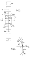
- the variation of the pairs C Is and C Js as a function of the angles y and Ay is then that shown in FIG. 4.
- the deflection angles of the wings necessary for piloting and for compensating the disturbing torques are of the order of maximum 6 °. , which only results in a maximum loss of wing efficiency of 0.5%. It can however be noted that keeping the wings in the nominal position would result in a windmill effect; but it is of very low intensity and can be compensated by a relative depointing Ay / 2 of the two wings relative to the nominal position whose effect on the yield is negligible.
- each wing 16a or 16b is symmetrically fixed two fins 20a or 20b, obliquely to the wing. These fins are placed on the sides of the wings so as to be at a distance from the pitch axis and as close as possible to the center of the satellite to reduce the roll and yaw torque due to the fins. The presence of the fins then makes it possible to create, by slight rotation in block of the two wings 16a and 16b, a significant torque in the direction of the pitch axis y, decoupled from the windmill effect obtained by deviation of deflection wings.
- the decoupling, total to the second order near, thus achieved, makes it possible to directly compensate for the solar disturbing couples in the directions Js and y.
- the device can be supplemented by means making it possible to create a torque in the direction Is, constituted for example by a magnetic coil so as to make piloting along three axes possible.
- the piloting itself can be controlled by conventional means from the signals provided by the sensors.
- the very constitution of the driving circuits, not being concerned with the invention, will not be described.
- the fins may therefore be of very low mass. They may for example be constituted by a frame made of piano strings on which is stretched a sail made of very fine material, having a mass of a few g / m 2 .
- a sail made of very fine material, having a mass of a few g / m 2 .
- the wings When launching the satellite, the wings are generally folded in an accordion.
- the fins can also be folded back and come into their service position, fixed by stops, during the deployment of the wings.
- Elastic deployment can easily be achieved due to the elasticity of the piano wire when the constitution adopted is that mentioned above.
Landscapes
- Engineering & Computer Science (AREA)
- Remote Sensing (AREA)
- Automation & Control Theory (AREA)
- Chemical & Material Sciences (AREA)
- Combustion & Propulsion (AREA)
- Radar, Positioning & Navigation (AREA)
- Aviation & Aerospace Engineering (AREA)
- Control Of Position, Course, Altitude, Or Attitude Of Moving Bodies (AREA)
Applications Claiming Priority (2)
| Application Number | Priority Date | Filing Date | Title |
|---|---|---|---|
| FR8211847A FR2530046A1 (fr) | 1982-07-06 | 1982-07-06 | Procede et dispositif de commande d'attitude pour satellite geosynchrone |
| FR8211847 | 1982-07-06 |
Publications (2)
| Publication Number | Publication Date |
|---|---|
| EP0101333A1 EP0101333A1 (fr) | 1984-02-22 |
| EP0101333B1 true EP0101333B1 (fr) | 1987-11-19 |
Family
ID=9275732
Family Applications (1)
| Application Number | Title | Priority Date | Filing Date |
|---|---|---|---|
| EP83401234A Expired EP0101333B1 (fr) | 1982-07-06 | 1983-06-16 | Procédé et dispositif de commande d'attitude pour satellite géosynchrone |
Country Status (3)
| Country | Link |
|---|---|
| EP (1) | EP0101333B1 (https=) |
| DE (1) | DE3374617D1 (https=) |
| FR (1) | FR2530046A1 (https=) |
Families Citing this family (14)
| Publication number | Priority date | Publication date | Assignee | Title |
|---|---|---|---|---|
| DE3329955A1 (de) * | 1983-08-19 | 1985-03-07 | Erno Raumfahrttechnik Gmbh, 2800 Bremen | Lageregelung von satelliten |
| FR2580582B1 (fr) * | 1985-04-19 | 1987-06-26 | Matra | Procede et dispositif d'amortissement de nutation de satellite par commande d'orientation de masses presentant un produit d'inertie variable |
| FR2615477B1 (fr) * | 1987-05-22 | 1989-08-18 | Centre Nat Etd Spatiales | Dispositif et procede de pointage d'une sonde spatiale vers un corps celeste |
| US4949922A (en) * | 1988-12-09 | 1990-08-21 | Hughes Aircraft Company | Satellite control system |
| FR2655167B1 (fr) * | 1989-11-29 | 1992-04-03 | Aerospatiale | Procede de controle d'attitude en roulis et en lacet d'un satellite. |
| FR2656586B1 (fr) * | 1989-12-29 | 1992-05-07 | Aerospatiale | Dispositif de controle d'attitude par voiles solaires pour satellite stabilise autour de trois axes. |
| DE4114804A1 (de) * | 1991-05-07 | 1992-11-12 | Messerschmitt Boelkow Blohm | Vorrichtung zur lageregelung von satelliten mit solardruckmomenten |
| FR2704515B1 (fr) * | 1993-04-27 | 1995-07-13 | Centre Nat Etd Spatiales | Satellite artificiel muni de gouvernes aerodynamiques d'orientation. |
| US5775645A (en) * | 1996-03-05 | 1998-07-07 | Hughes Electronics Corporation | Controlled-emission solar tabs for attitude solar sailing |
| FR2765189B1 (fr) * | 1997-06-25 | 1999-08-20 | Agence Spatiale Europeenne | Dispositif de stabilisation passive de la direction de pointage d'un engin spatial |
| FR2848529B1 (fr) | 2002-12-12 | 2005-02-25 | Astrium Sas | Procede de pilotage solaire de vehicule spatial |
| KR100573876B1 (ko) | 2004-07-13 | 2006-04-25 | 한국과학기술원 | 태양 복사 압력을 이용하여 타원 궤도에 있는 위성 자세제어 방법 |
| FR2980176A1 (fr) | 2011-09-19 | 2013-03-22 | Astrium Sas | Procede de controle d'attitude d'un satellite et satellite commande en attitude |
| CN102431659B (zh) * | 2011-10-27 | 2013-07-24 | 北京航空航天大学 | 一种日地系统Halo轨道探测器的构型及其姿态指向 |
Family Cites Families (2)
| Publication number | Priority date | Publication date | Assignee | Title |
|---|---|---|---|---|
| DE2537577A1 (de) * | 1975-08-22 | 1977-03-03 | Michael Dipl Ing Truemper | Lagerregelung fuer satelliten |
| DE2604005A1 (de) * | 1976-02-03 | 1977-08-11 | Messerschmitt Boelkow Blohm | Einrichtung zur beeinflussung der position und lage eines satelliten |
-
1982
- 1982-07-06 FR FR8211847A patent/FR2530046A1/fr active Granted
-
1983
- 1983-06-16 DE DE8383401234T patent/DE3374617D1/de not_active Expired
- 1983-06-16 EP EP83401234A patent/EP0101333B1/fr not_active Expired
Also Published As
| Publication number | Publication date |
|---|---|
| FR2530046B1 (https=) | 1985-01-18 |
| FR2530046A1 (fr) | 1984-01-13 |
| EP0101333A1 (fr) | 1984-02-22 |
| DE3374617D1 (en) | 1987-12-23 |
Similar Documents
| Publication | Publication Date | Title |
|---|---|---|
| EP0101333B1 (fr) | Procédé et dispositif de commande d'attitude pour satellite géosynchrone | |
| EP0435708B1 (fr) | Procédé de contrôle d'attitude en roulis et en lacet d'un satellite | |
| EP0436425B1 (fr) | Dispositif de contrôle d'attitude par voiles solaires pour satellite stabilisé autour de trois axes | |
| EP0778201B1 (fr) | Procédé de commande d'attitude d'un satellite en orbite basse, a acquisition solaire | |
| EP2643215B1 (fr) | Dispositif de contrôle d'attitude d'un satellite et procédé de commande d'un satellite embarquant ledit dispositif | |
| EP1002716B1 (fr) | Procédé et dispositif de pilotage de l'attitude d'un satellite | |
| EP2690020B1 (fr) | Procédé de réduction du moment cinétique et de contrôle d' attitude d' un engin spatial | |
| EP3253655B1 (fr) | Système d'aérofreinage pour désorbitation de satellite | |
| EP2181923B1 (fr) | Procédé et système de désaturation des roues d'inertie d'un engin spatial | |
| FR2669887A1 (fr) | Procede de controle d'attitude en tangage d'un satellite grace a la pression de radiation solaire et satellite adapte a sa mise en óoeuvre. | |
| EP3074309B1 (fr) | Procédé et dispositif de commande d'une phase d'acquisition du soleil par un engin spatial | |
| FR2529166A1 (fr) | Procede de maintien en position d'un satellite par la navigation a l'aide de voiles solaires et vehicule spatial mettant en oeuvre le procede | |
| EP2282940A1 (fr) | Procédé de commande d'attitude de satellite et satellite commandé en attitude | |
| EP3248079B1 (fr) | Procédé et dispositif de contrôle d'attitude d'un engin spatial | |
| FR2729116A1 (fr) | Procede de commande d'attitude de satellite sur orbite inclinee sur l'equateur terrestre | |
| EP3038923B1 (fr) | Procédé et dispositif de propulsion électrique de satellite | |
| FR2522614A1 (fr) | Configuration de satellite a orbite equatoriale a moyens solaires perfectionnes | |
| EP0295978B1 (fr) | Dispositif et procédé de pointage d'une sonde spatiale vers un corps céleste | |
| EP0917799B1 (fr) | Procede pour l'acquisition d'une image par balayage pousse-balai surechantillonne | |
| EP1569847B1 (fr) | Procede de pilotage solaire de vehicule spatial | |
| FR2765189A1 (fr) | Dispositif de stabilisation passive de la direction de pointage d'un engin spatial | |
| EP1635485B1 (fr) | Procédé de transmission optique entre un terminal embarqué sur un engin spatial et un terminal distant, et engin spatial adapté pour un tel procédé | |
| EP1312997B1 (fr) | Procédé de commande d'attitude et de stabilisation d'un satellite en orbite basse, par couplage avec le champ magnétique terrestre | |
| FR2815730A1 (fr) | Procede de commande d'attitude et de stabilisation d'un satellite en orbite basse, par couplage avec le champ magnetique terrestre | |
| FR2725331A1 (fr) | Procede d'exploitation de satellites stabilises et places sur orbite terrestre |
Legal Events
| Date | Code | Title | Description |
|---|---|---|---|
| PUAI | Public reference made under article 153(3) epc to a published international application that has entered the european phase |
Free format text: ORIGINAL CODE: 0009012 |
|
| AK | Designated contracting states |
Designated state(s): DE GB IT NL SE |
|
| 17P | Request for examination filed |
Effective date: 19840307 |
|
| GRAA | (expected) grant |
Free format text: ORIGINAL CODE: 0009210 |
|
| AK | Designated contracting states |
Kind code of ref document: B1 Designated state(s): DE GB IT NL SE |
|
| ITF | It: translation for a ep patent filed | ||
| PG25 | Lapsed in a contracting state [announced via postgrant information from national office to epo] |
Ref country code: SE Effective date: 19871130 |
|
| REF | Corresponds to: |
Ref document number: 3374617 Country of ref document: DE Date of ref document: 19871223 |
|
| GBT | Gb: translation of ep patent filed (gb section 77(6)(a)/1977) | ||
| PLBE | No opposition filed within time limit |
Free format text: ORIGINAL CODE: 0009261 |
|
| STAA | Information on the status of an ep patent application or granted ep patent |
Free format text: STATUS: NO OPPOSITION FILED WITHIN TIME LIMIT |
|
| 26N | No opposition filed | ||
| ITTA | It: last paid annual fee | ||
| PGFP | Annual fee paid to national office [announced via postgrant information from national office to epo] |
Ref country code: NL Payment date: 19990518 Year of fee payment: 17 |
|
| PGFP | Annual fee paid to national office [announced via postgrant information from national office to epo] |
Ref country code: GB Payment date: 19990608 Year of fee payment: 17 |
|
| PGFP | Annual fee paid to national office [announced via postgrant information from national office to epo] |
Ref country code: DE Payment date: 19990617 Year of fee payment: 17 |
|
| PG25 | Lapsed in a contracting state [announced via postgrant information from national office to epo] |
Ref country code: GB Free format text: LAPSE BECAUSE OF NON-PAYMENT OF DUE FEES Effective date: 20000616 |
|
| PG25 | Lapsed in a contracting state [announced via postgrant information from national office to epo] |
Ref country code: NL Free format text: LAPSE BECAUSE OF NON-PAYMENT OF DUE FEES Effective date: 20010101 |
|
| GBPC | Gb: european patent ceased through non-payment of renewal fee |
Effective date: 20000616 |
|
| NLV4 | Nl: lapsed or anulled due to non-payment of the annual fee |
Effective date: 20010101 |
|
| PG25 | Lapsed in a contracting state [announced via postgrant information from national office to epo] |
Ref country code: DE Free format text: LAPSE BECAUSE OF NON-PAYMENT OF DUE FEES Effective date: 20010403 |