EP0101152B1 - Mechanical seal having a seal insert mounted in a laminated shell - Google Patents
Mechanical seal having a seal insert mounted in a laminated shell Download PDFInfo
- Publication number
- EP0101152B1 EP0101152B1 EP83302948A EP83302948A EP0101152B1 EP 0101152 B1 EP0101152 B1 EP 0101152B1 EP 83302948 A EP83302948 A EP 83302948A EP 83302948 A EP83302948 A EP 83302948A EP 0101152 B1 EP0101152 B1 EP 0101152B1
- Authority
- EP
- European Patent Office
- Prior art keywords
- insert
- holder
- band
- seal
- bands
- Prior art date
- Legal status (The legal status is an assumption and is not a legal conclusion. Google has not performed a legal analysis and makes no representation as to the accuracy of the status listed.)
- Expired
Links
- 230000006835 compression Effects 0.000 claims description 18
- 238000007906 compression Methods 0.000 claims description 18
- 229910052751 metal Inorganic materials 0.000 claims description 3
- 239000002184 metal Substances 0.000 claims description 3
- 239000000463 material Substances 0.000 claims description 2
- 230000037431 insertion Effects 0.000 claims 1
- 238000003780 insertion Methods 0.000 claims 1
- 239000007769 metal material Substances 0.000 claims 1
- 238000010276 construction Methods 0.000 description 6
- 238000013459 approach Methods 0.000 description 5
- 239000012530 fluid Substances 0.000 description 4
- 239000002783 friction material Substances 0.000 description 4
- OKTJSMMVPCPJKN-UHFFFAOYSA-N Carbon Chemical compound [C] OKTJSMMVPCPJKN-UHFFFAOYSA-N 0.000 description 3
- 230000000712 assembly Effects 0.000 description 3
- 238000000429 assembly Methods 0.000 description 3
- 229910052799 carbon Inorganic materials 0.000 description 3
- PXHVJJICTQNCMI-UHFFFAOYSA-N Nickel Chemical compound [Ni] PXHVJJICTQNCMI-UHFFFAOYSA-N 0.000 description 2
- 238000007792 addition Methods 0.000 description 2
- 238000012986 modification Methods 0.000 description 2
- 230000004048 modification Effects 0.000 description 2
- 238000000926 separation method Methods 0.000 description 2
- 238000006467 substitution reaction Methods 0.000 description 2
- 230000002459 sustained effect Effects 0.000 description 2
- VYZAMTAEIAYCRO-UHFFFAOYSA-N Chromium Chemical compound [Cr] VYZAMTAEIAYCRO-UHFFFAOYSA-N 0.000 description 1
- 230000002411 adverse Effects 0.000 description 1
- 229910052804 chromium Inorganic materials 0.000 description 1
- 239000011651 chromium Substances 0.000 description 1
- 230000007797 corrosion Effects 0.000 description 1
- 238000005260 corrosion Methods 0.000 description 1
- 230000000694 effects Effects 0.000 description 1
- 238000005516 engineering process Methods 0.000 description 1
- 239000007789 gas Substances 0.000 description 1
- 238000009434 installation Methods 0.000 description 1
- 229910052759 nickel Inorganic materials 0.000 description 1
- 239000010955 niobium Substances 0.000 description 1
- GUCVJGMIXFAOAE-UHFFFAOYSA-N niobium atom Chemical compound [Nb] GUCVJGMIXFAOAE-UHFFFAOYSA-N 0.000 description 1
- 230000006641 stabilisation Effects 0.000 description 1
- 238000011105 stabilization Methods 0.000 description 1
- 229910001220 stainless steel Inorganic materials 0.000 description 1
- 239000010935 stainless steel Substances 0.000 description 1
- 239000000126 substance Substances 0.000 description 1
Images

Classifications
-
- F—MECHANICAL ENGINEERING; LIGHTING; HEATING; WEAPONS; BLASTING
- F16—ENGINEERING ELEMENTS AND UNITS; GENERAL MEASURES FOR PRODUCING AND MAINTAINING EFFECTIVE FUNCTIONING OF MACHINES OR INSTALLATIONS; THERMAL INSULATION IN GENERAL
- F16J—PISTONS; CYLINDERS; SEALINGS
- F16J15/00—Sealings
- F16J15/16—Sealings between relatively-moving surfaces
- F16J15/34—Sealings between relatively-moving surfaces with slip-ring pressed against a more or less radial face on one member
- F16J15/3464—Mounting of the seal
- F16J15/3468—Means for controlling the deformations of the contacting faces
Definitions
- the present invention relates to a mechanical seal of the type which includes a rotatable member and a non-rotatable member provided with confronting radial faces and which are biased into rubbing engagement, and more particularly to a seal of this type which includes a laminated holder and a low-friction insert which , forms one of said members.
- Mechanical face seals of the type to which the present invention relates are used to seal an opening in the wall of a pressurized container through which a rotatable shaft extends.
- These seal assemblies include rings one of which is non- rotatably carried by the container and the other fixed to the shaft.
- One of the rings is provided with an insert constructed of a low friction material having a radial face which confronts a machined radial face on the other ring.
- One of the rings is biased toward the other so that the confronting faces of the rings rubbingly engage and maintain a pressure seal between the shaft and container wall.
- the low friction insert is a non-metallic annular member press fitted in a holder, usually a metallic ring. It is important that the holder and insert assembly remain stable i.e., not distort or become loose during operation of the device. To this end, it is important that this assembly remain stable and resist distortion and separation throughout a range of temperatures which are expected to develop on the seal during its use, and under stresses which arise as a result of pressure in the container and centrifugal forces during rotation of the seal.
- temperature rise occurs mainly from the sealed fluid in the container and from friction during use of the seal and causes the assembled holder and insert to expand.
- the coefficient of expansion of the metallic holder is different from that of the non-metallic insert so that a sufficient temperature rise can cause the insert to become loose in the holder thereby destroying the seal.
- sufficient expansion of the holder relative to the insert can weaken the connection between their parts allowing distortion of the assembly and resultant seal loss.
- a mechanical seal comprising rotatable and non-rotatable members rubbingly engageable along substantially radial faces, one of the members being an annular insert formed with one of the rubbingly engageable faces and accommodated in a casing, a layer of material being interposed between the casing and the insert such that stresses in the casing and the insert tend to balance one another.
- the present invention overcomes the problems and disadvantages discussed above by providing a seal insert and holder assembly which is stable and maintains an effective seal over a wide range of temperatures, and which resists adverse effects of pressure, heat, friction and centrifugal force.
- a mechanical face seal comprising rotatable and non-rotatable members rubbingly engageable along substantially radial faces, one of said members being held by a holder, said one member being an annular insert and formed with one of said rubbingly engageable faces, characterized in that the holder is formed by at least two bands which are press-fitted to one another, the annular insert is press-fitted into the holder, the outermost band is in tension and, at least in the absence of the insert, the innermost band is in compression so that the stresses in the bands tend to balance one another.
- the preferred embodiment of the present invention includes a holder and insert assembly which is illustrated generally at 11 in Fig. 1 and is seen to be part of mechanical face seal 13 which provides a pressure seal between an opening formed in a container (not shown) and a rotatable shaft 19.
- the container can be a housing for a pump, compressor, gear box, or the like used in such installations as aerospace, refineries, chemical plants, etc. where pressurized fluids of gases in a container must be sealed.
- the seal 13 includes a seal ring 25 which is fixed to the housing at its opening.
- the assembly 11 includes an annular insert 29 formed of a low friction material such as carbon and provided with a radial face 30, and which is mounted in a holder 27.
- the radial face 30 on the insert confronts and rubbingly engages a radial face 28 on seal ring 25.
- the assembly 11 is fixed for rotation with the shaft 19 and is biased by a resilient bellows 33 toward the holder 27 to maintain rubbing engagement between the faces 28, 30. This forms a primary seal between the shaft 19 and the container.
- the assembly 11 of the present invention finds a particular use as the rotatable component of a mechanical face seal because of the high stresses developed in this component.
- this invention may also be used in connection with an insert used in the non-rotatable component of such seals.
- the insert 29 is constructed of a low-friction material such as carbon and has a somewhat lower coefficient of expansion than the holder 27 which is constructed of metal.
- the holder 27 generally is a single metallic ring or band and even though the holder 27 and insert 29 are press-fitted together, heat generated by the temperature of the surrounding fluid and by friction in the seal causes the holder 27 to expand relative to the insert 29. This reduces the strength and stability of the assembled holder and insert and its ability to maintain a proper seal under the developed stresses. Furthermore, these elevated temperatures can cause the holder 27 to distort so that the rubbing face 30 on the insert 29 is no longer flat or parallel to the rubbing face 28 on the ring 25 thereby allowing pressure leakage across the seal. Finally, sufficiently high temperatures can cause the holder 27 to expand to a point where the press fit between the insert 29 and holder 27 is lost. This too causes leakage to occur between these parts.
- the present invention overcomes the aforementioned problems by providing a holder and insert assembly which results in a stronger and more stable construction and one which resists distortion or separation of the component parts over a wide range of temperatures.
- the construction of this invention includes at least two metallic bands which are press-fitted together to form a laminated holder, and a non-metallic insert constructed of a low friction material pressed into the laminated holder. When assembled, the holder outer band is in tension and the inner band in compression so that the generated stresses in these parts tend to balance each other.
- the resultant holder is stronger and more stable than a holder constructed of a single band and maintains an effective seal over a wide range of temperatures.
- the holder 27 includes two concentric bands 35, 37, which are press-fitted together to form the laminated holder 27.
- the bands 35, 37 are preferably constructed of stamped sheet metal and may be formed with inturned ends which abut in the assembled condition. The other ends of the bands align with one another as shown.
- the insert 29 is press-fitted in the laminated holder 27 and its outer end extends axially beyond the assembled bands 35, 37 as shown.
- the rubbing face 30 is formed on the outer end of the insert 29.
- the outer band 35 is in tension and the inner band 37 in compression when these bands are press-fitted together to form the holder 27.
- the insert 29 When the insert 29 is pressed into the holder 27, it will be understood that compression loading on the inner band 27 is reduced and, in some cases, the band 37 may be in tension. Of course, the insert 29 is compression loaded.
- the insert 29 and the seal ring 25 are in rubbing engagement and the assembled holder 27 and the insert 29 become heated by the surrounding fluid and by friction between the insert and seal ring.
- the coefficient of expansion for the laminated metallic holder 27 is higher than that for the insert 29 so that there is a tendency for the holder 27 to expand faster than the insert 29.
- the integrity of the holder 27 and insert 29 is maintained throughout a higher range of temperatures than would be if only a single band or ring is used for the holder 27.
- the assembled holder 27 and insert 29 form a stronger construction which is better able to withstand stresses in the system and which maintains flatness of the insert rubbing face 28.
- a double ring and insert assembly has the following dimensions:
- the bands 35, 37 are constructed of Carpenter 20cb-3 which is a corrosion-resistant stainless steel containing about 20% chromium, about 30-35% nickel, and columbium for stabilization, and is a product of Carpenter Technology Corporation.
- the insert 29 is constructed of carbon.
- the bands 35, 37 have a modulus of elasticity of 193 GPa, a Poisson ratio of .300, a coefficient of thermal expansion of 1.69x10- 5 /°C, and a yield point of 379 MPa.
- the insert 29 has a modulus of elasticity of 20.7 GPa, a Poisson ratio of 0.16, a coefficient of thermal expansion of 4.68x10- s /°C, and a yield stress of 248 MPa.
- the outer band 35 is stressed in tension beyond its yield point so that it is in tension at 3.79 MPa.
- Initial assembly of the inner ring 37 in the outer band 35 puts the inner band 37 in compression but after the insert 29 is pressed in place, the band 37 is stressed to approximately 76 MPa in tension.
- Insert 29 is in compression and is stressed to approximately 61 MPa at its OD and 69 MPa at its ID.
- the bands 35, 37 have an interference fit of about 0.102mm, and, as described above, there is about 0.178mm interference between the inner band 37 and the insert 29.
- the band When assembled, the band is in tension at 231 MPa while the insert is in compression at 39 MPa at its OD and 46 MPa at its ID.
- the calculations show that for maximum wall thickness for the band, interference between the parts approaches zero, i.e., 0.051mm at a temperature rise of 190°C compared to 224°C for the double band assembly of Example 1.
- the assembly can sustain a temperature rise of 182°C.
- the same maximum allowable temperature rise, i.e., 182°C was found for this assembly at 0.279mm interference.
- the double band assembly at 0.178mm interference can operate at a temperature of 31°C higher than a single band assembly stressed below its yield point, and 39°C higher than the single band assembly stressed to its yield point.
- the double band assembly can operate at a temperature of 171°C higher than the single band assembly initially stressed below its yield point.
Landscapes
- Engineering & Computer Science (AREA)
- General Engineering & Computer Science (AREA)
- Mechanical Engineering (AREA)
- Gasket Seals (AREA)
- Mechanical Sealing (AREA)
- Sealing Devices (AREA)
Description
- The present invention relates to a mechanical seal of the type which includes a rotatable member and a non-rotatable member provided with confronting radial faces and which are biased into rubbing engagement, and more particularly to a seal of this type which includes a laminated holder and a low-friction insert which , forms one of said members.
- Mechanical face seals of the type to which the present invention relates are used to seal an opening in the wall of a pressurized container through which a rotatable shaft extends. These seal assemblies include rings one of which is non- rotatably carried by the container and the other fixed to the shaft. One of the rings is provided with an insert constructed of a low friction material having a radial face which confronts a machined radial face on the other ring. One of the rings is biased toward the other so that the confronting faces of the rings rubbingly engage and maintain a pressure seal between the shaft and container wall.
- The low friction insert is a non-metallic annular member press fitted in a holder, usually a metallic ring. It is important that the holder and insert assembly remain stable i.e., not distort or become loose during operation of the device. To this end, it is important that this assembly remain stable and resist distortion and separation throughout a range of temperatures which are expected to develop on the seal during its use, and under stresses which arise as a result of pressure in the container and centrifugal forces during rotation of the seal.
- It will be appreciated that temperature rise occurs mainly from the sealed fluid in the container and from friction during use of the seal and causes the assembled holder and insert to expand. The coefficient of expansion of the metallic holder is different from that of the non-metallic insert so that a sufficient temperature rise can cause the insert to become loose in the holder thereby destroying the seal. Also, sufficient expansion of the holder relative to the insert can weaken the connection between their parts allowing distortion of the assembly and resultant seal loss.
- From DE-A-2 636 507 is known a mechanical seal comprising rotatable and non-rotatable members rubbingly engageable along substantially radial faces, one of the members being an annular insert formed with one of the rubbingly engageable faces and accommodated in a casing, a layer of material being interposed between the casing and the insert such that stresses in the casing and the insert tend to balance one another.
- The present invention overcomes the problems and disadvantages discussed above by providing a seal insert and holder assembly which is stable and maintains an effective seal over a wide range of temperatures, and which resists adverse effects of pressure, heat, friction and centrifugal force.
- Further objects of the invention are to provide an improved holder and insert assembly of the above character which is relatively inexpensive and easy to construct.
- In accordance with the present invention there is provided a mechanical face seal comprising rotatable and non-rotatable members rubbingly engageable along substantially radial faces, one of said members being held by a holder, said one member being an annular insert and formed with one of said rubbingly engageable faces, characterized in that the holder is formed by at least two bands which are press-fitted to one another, the annular insert is press-fitted into the holder, the outermost band is in tension and, at least in the absence of the insert, the innermost band is in compression so that the stresses in the bands tend to balance one another.
- The accompanying drawings which are incorporated in and constitute a part of this specification, illustrate an embodiment of the invention and, together with the description that follows, serve to explain the principles of the invention.
-
- Fig. 1 is a sectional view showing a mechanical face seal embodying a preferred form of the present invention; and
- Fig. 2 is a plan view of the holder and insert assembly of the present invention.
- Reference will now be made in detail to the present preferred embodiment of the invention, an example of which is illustrated in the accompanying drawings.
- The preferred embodiment of the present invention includes a holder and insert assembly which is illustrated generally at 11 in Fig. 1 and is seen to be part of
mechanical face seal 13 which provides a pressure seal between an opening formed in a container (not shown) and arotatable shaft 19. The container can be a housing for a pump, compressor, gear box, or the like used in such installations as aerospace, refineries, chemical plants, etc. where pressurized fluids of gases in a container must be sealed. - The
seal 13 includes aseal ring 25 which is fixed to the housing at its opening. The assembly 11 includes anannular insert 29 formed of a low friction material such as carbon and provided with aradial face 30, and which is mounted in aholder 27. Theradial face 30 on the insert confronts and rubbingly engages aradial face 28 onseal ring 25. The assembly 11 is fixed for rotation with theshaft 19 and is biased by aresilient bellows 33 toward theholder 27 to maintain rubbing engagement between thefaces shaft 19 and the container. - It will be understood that the assembly 11 of the present invention finds a particular use as the rotatable component of a mechanical face seal because of the high stresses developed in this component. However, this invention may also be used in connection with an insert used in the non-rotatable component of such seals.
- The
insert 29 is constructed of a low-friction material such as carbon and has a somewhat lower coefficient of expansion than theholder 27 which is constructed of metal. Theholder 27 generally is a single metallic ring or band and even though theholder 27 andinsert 29 are press-fitted together, heat generated by the temperature of the surrounding fluid and by friction in the seal causes theholder 27 to expand relative to theinsert 29. This reduces the strength and stability of the assembled holder and insert and its ability to maintain a proper seal under the developed stresses. Furthermore, these elevated temperatures can cause theholder 27 to distort so that the rubbingface 30 on theinsert 29 is no longer flat or parallel to the rubbingface 28 on thering 25 thereby allowing pressure leakage across the seal. Finally, sufficiently high temperatures can cause theholder 27 to expand to a point where the press fit between theinsert 29 andholder 27 is lost. This too causes leakage to occur between these parts. - The present invention overcomes the aforementioned problems by providing a holder and insert assembly which results in a stronger and more stable construction and one which resists distortion or separation of the component parts over a wide range of temperatures. The construction of this invention includes at least two metallic bands which are press-fitted together to form a laminated holder, and a non-metallic insert constructed of a low friction material pressed into the laminated holder. When assembled, the holder outer band is in tension and the inner band in compression so that the generated stresses in these parts tend to balance each other. The resultant holder is stronger and more stable than a holder constructed of a single band and maintains an effective seal over a wide range of temperatures.
- When the
insert 29 is pressed into the laminated holder, the compression loading on the inner band is reduced and, in fact, that band may be loaded now in tension. Even in those cases, however, the amount of tension loading on the inner band is reduced as the assembly is heated and the inner band becomes compression loaded at elevated temperatures. In either event, the overall stresses in this assembly formed of the laminated holder and insert tend to balance one another so that the assembly remains strong and stable over a wide range of temperatures. - As embodied herein, the
holder 27 includes twoconcentric bands holder 27. Thebands insert 29 is press-fitted in the laminatedholder 27 and its outer end extends axially beyond the assembledbands face 30 is formed on the outer end of theinsert 29. - As further embodied herein and described above, the
outer band 35 is in tension and theinner band 37 in compression when these bands are press-fitted together to form theholder 27. When theinsert 29 is pressed into theholder 27, it will be understood that compression loading on theinner band 27 is reduced and, in some cases, theband 37 may be in tension. Of course, theinsert 29 is compression loaded. - During use, the
insert 29 and theseal ring 25 are in rubbing engagement and the assembledholder 27 and theinsert 29 become heated by the surrounding fluid and by friction between the insert and seal ring. The coefficient of expansion for the laminatedmetallic holder 27 is higher than that for theinsert 29 so that there is a tendency for theholder 27 to expand faster than theinsert 29. However, because of the press-fit between thebands holder 27 andinsert 29 is maintained throughout a higher range of temperatures than would be if only a single band or ring is used for theholder 27. Furthermore, the assembledholder 27 and insert 29 form a stronger construction which is better able to withstand stresses in the system and which maintains flatness of theinsert rubbing face 28. - The following examples are based on calculations made to illustrate comparisons between a standard single band holder and a double band laminated holder and to point out the advantages of the present invention. Specifically, the following examples illustrate the maximum temperature rise which can be sustained by standard assembled inserts and holders (single band) and assembled inserts and holder (double band) according to this invention before loss of integrity between the parts. It will be appreciated that these calculations are also representative of the relative strengths of the assembled holders and inserts.
- A double ring and insert assembly, according to the present invention, has the following dimensions:
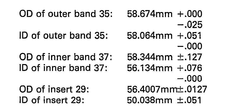
bands insert 29 is constructed of carbon. Thebands insert 29 has a modulus of elasticity of 20.7 GPa, a Poisson ratio of 0.16, a coefficient of thermal expansion of 4.68x10-s/°C, and a yield stress of 248 MPa. - For the maximum wall thicknesses of
bands insert 29 and theinner band 37, theouter band 35 is stressed in tension beyond its yield point so that it is in tension at 3.79 MPa. Initial assembly of theinner ring 37 in theouter band 35 puts theinner band 37 in compression but after theinsert 29 is pressed in place, theband 37 is stressed to approximately 76 MPa in tension.Insert 29 is in compression and is stressed to approximately 61 MPa at its OD and 69 MPa at its ID. Thebands inner band 37 and theinsert 29. - Calculations show that when this assembly is exposed to a temperature rise of about 224°C, the inner and
outer bands holder 27 expands faster than theinsert 29 and interference between these parts approaches zero, approximately.0236 mm at this temperature rise.Outer band 35 remains in tension at about 234 MPa whileinner band 37 now is in compression at 66 MPa.Insert 29 is in compression at 17 MPa at its OD and 19 MPa at its ID. Thus, for this example, integrity of the parts is maintained at a temperature rise of up to about 224°C. - The same calculations were made for an assembly where the interference between the
insert 29 andinner band 37 is 0.178mm but with the minimum wall thickness for thebands outer band 35 is stressed beyond its elastic limit and is in tension at 379 MPa.Inner band 37 is also in tension at 97 MPa, while theinsert 29 is in compression at 59 MPa at its OD and 67 MPa at its ID. Effective interference is maintained between all the parts. - When this assembly is exposed to a temperature rise of about 221°C, interference between the
inner band 37 and theinsert 29 approaches zero, i.e., .025 mm.Outer band 35 remains in tension at 224 MPa whileinner band 37 is in compression at 62 MPa.Insert 27 is in compression at its OD at 172 MPa and its ID at 193 MPa. The maximum operating range limit for this example is a temperature rise of about 221°C. - Calculations were made for the insert and double band assembly where the interference between the
insert 29 and theinner band 37 is 0.279mm and for maximum wall thickness of the outer andinner bands inner band 37 and theinsert 29 approaches zero, i.e., 0.025mm. Theouter band 35 is in tension at 170 MPa, theinner band 37 is in compression at 46 MPa, and theinsert 29 is in compression at 17 MPa at its OD at 19 MPa at its ID. - Calculations for an assembly having 0.279mm interference between the
inner band 37 andinsert 29, and minimum wall thicknesses for thebands - Calculations were also made for an assembly utilizing a single band and insert wherein the band and insert have an interference of 0.178mm and wherein the band remains below its yield point. The
same insert 29 dimensions identified above in Example 1 were used and the single band has an OD of -

-

- When assembled, the band is in tension at 231 MPa while the insert is in compression at 39 MPa at its OD and 46 MPa at its ID. The calculations show that for maximum wall thickness for the band, interference between the parts approaches zero, i.e., 0.051mm at a temperature rise of 190°C compared to 224°C for the double band assembly of Example 1.
- The same calculations were made for a single band holder and insert assembly as described above in Example 5 except that minimum wall thickness for the band was used. Again, interference approaches zero, i.e. 0.051mm, at a temperature rise of 190°C compared to 221°C for
- Calculations were made on the same assemblies as in Example 5 and 6 above except that interference between the band and the insert was set at 0.279mm. The maximum temperature rise which can be sustained by this construction is 190°C compared to 364°C and 361°C for Examples 3 and 4.
- Finally, calculations were made for a single band holder and insert assembly using the same dimensional insert as described above and a band which is stressed to its yield point at assembly. The OD of the band is
-


- From the examples described above, it is apparent that the double band assembly at 0.178mm interference can operate at a temperature of 31°C higher than a single band assembly stressed below its yield point, and 39°C higher than the single band assembly stressed to its yield point. For assemblies with 0.279mm interference, the double band assembly can operate at a temperature of 171°C higher than the single band assembly initially stressed below its yield point. Thus, the present invention represents a substantial improvement over previous constructions utilizing a single band in maintaining seal integrity at higher operating temperatures.
- It will be apparent to those skilled in the art that various additions, substitutions, modifications, and omissions can be made to the construction of the present invention without departing from the scope or spirit of the invention, and it is intended that the present invention cover those additions, substitutions, modifications, and omissions provided they come within the scope of the appended claims and their equivalents.
Claims (6)
Applications Claiming Priority (2)
| Application Number | Priority Date | Filing Date | Title |
|---|---|---|---|
| US06/398,927 US4389050A (en) | 1982-07-16 | 1982-07-16 | Mechanical seal having a seal insert mounted in a laminated shell |
| US398927 | 1982-07-16 |
Publications (3)
| Publication Number | Publication Date |
|---|---|
| EP0101152A2 EP0101152A2 (en) | 1984-02-22 |
| EP0101152A3 EP0101152A3 (en) | 1985-11-06 |
| EP0101152B1 true EP0101152B1 (en) | 1988-12-14 |
Family
ID=23577380
Family Applications (1)
| Application Number | Title | Priority Date | Filing Date |
|---|---|---|---|
| EP83302948A Expired EP0101152B1 (en) | 1982-07-16 | 1983-05-23 | Mechanical seal having a seal insert mounted in a laminated shell |
Country Status (6)
| Country | Link |
|---|---|
| US (1) | US4389050A (en) |
| EP (1) | EP0101152B1 (en) |
| JP (1) | JPS5926670A (en) |
| CA (1) | CA1183181A (en) |
| DE (1) | DE3378693D1 (en) |
| IE (1) | IE54296B1 (en) |
Families Citing this family (2)
| Publication number | Priority date | Publication date | Assignee | Title |
|---|---|---|---|---|
| JP4889419B2 (en) * | 2006-09-15 | 2012-03-07 | 愛三工業株式会社 | Wesco pump |
| US9157518B2 (en) | 2012-12-06 | 2015-10-13 | Electro-Motive Diesel, Inc. | Seal having integral insert |
Family Cites Families (10)
| Publication number | Priority date | Publication date | Assignee | Title |
|---|---|---|---|---|
| DE851575C (en) * | 1940-05-04 | 1952-10-06 | Riv Officine Di Villar Perosa | Rolling bearing installation in a material with a significantly higher coefficient of thermal expansion than that of the rolling bearing material |
| NL94086C (en) * | 1950-06-05 | |||
| FR1076314A (en) * | 1953-03-10 | 1954-10-26 | Improvements to sealing devices between fixed part and rotating part | |
| US2866656A (en) * | 1953-04-29 | 1958-12-30 | Internat Engineering General R | Mechanical seal between rotary and coaxial mechanical members |
| GB809458A (en) * | 1955-11-01 | 1959-02-25 | Gits Bros Mfg Co | Improvements in or relating to sealing devices between relatively rotatable elements |
| FR1157402A (en) * | 1956-08-14 | 1958-05-29 | Improvement of sealing devices between rotating part and fixed part | |
| US3160418A (en) * | 1960-04-14 | 1964-12-08 | Barske Ulrich Max Willi | Spring-loaded seal with coaxial relatively rotating contact faces |
| US3157404A (en) * | 1962-03-19 | 1964-11-17 | Jabsco Pump Co | Shaft seal with corrugated frustoconical spring for driving or restraining sealing member |
| US3695791A (en) * | 1970-09-18 | 1972-10-03 | Emerson Electric Co | Variable sealed hydraulic pump or motor |
| DE2636507A1 (en) * | 1976-08-13 | 1978-02-16 | Conradty Nuernberg | Shaft bearing system compensating for thermal expansion - has bearing support or sealing element made of layers of different materials |
-
1982
- 1982-07-16 US US06/398,927 patent/US4389050A/en not_active Expired - Lifetime
-
1983
- 1983-03-30 CA CA000424942A patent/CA1183181A/en not_active Expired
- 1983-04-12 IE IE826/83A patent/IE54296B1/en not_active IP Right Cessation
- 1983-05-23 EP EP83302948A patent/EP0101152B1/en not_active Expired
- 1983-05-23 DE DE8383302948T patent/DE3378693D1/en not_active Expired
- 1983-07-14 JP JP58127063A patent/JPS5926670A/en active Granted
Also Published As
| Publication number | Publication date |
|---|---|
| DE3378693D1 (en) | 1989-01-19 |
| EP0101152A2 (en) | 1984-02-22 |
| IE54296B1 (en) | 1989-08-16 |
| CA1183181A (en) | 1985-02-26 |
| EP0101152A3 (en) | 1985-11-06 |
| JPS63666B2 (en) | 1988-01-08 |
| JPS5926670A (en) | 1984-02-10 |
| US4389050A (en) | 1983-06-21 |
| IE830826L (en) | 1984-01-16 |
Similar Documents
| Publication | Publication Date | Title |
|---|---|---|
| EP0163450B1 (en) | Improvements in mechanical seals | |
| EP0277724B1 (en) | Pressure balanced s-seal | |
| US4854600A (en) | Pressure balanced metallic S-seal | |
| US5022663A (en) | Metal gasket or joint provided with an extremely high unit-area pressure | |
| EP0038170B1 (en) | Mechanical seal with improved face ring mounting | |
| EP0922891A2 (en) | Rotary, reciprocating seals with internal metal band | |
| US3443814A (en) | Hydraulically balanced radial seal | |
| US5295786A (en) | Liner ring for a pump | |
| US3240501A (en) | Gastight gasket joint | |
| US4206537A (en) | Method of making a sight glass assembly | |
| US4169309A (en) | Method of making a sight glass assembly | |
| US4438936A (en) | Secondary sealing element with U-shaped sealing ring for mechanical seals | |
| KR910002732B1 (en) | Mechanical seal assembly | |
| US4448428A (en) | Mechanical seal assembly | |
| US3193298A (en) | Cartridge type face seal | |
| WO2001029456A9 (en) | An improved face seal | |
| EP0101152A2 (en) | Mechanical seal having a seal insert mounted in a laminated shell | |
| US3452994A (en) | Mechanical face seal | |
| EP0029686B1 (en) | Continuous self-locking spiral wound seal | |
| US3836216A (en) | Pressure balanced seal assembly | |
| US12018756B2 (en) | Compact seal packing to ensure sealing between a rotary shaft and a stationary body of a machine | |
| US4384727A (en) | Circumferential ring seal assembly | |
| GB2290587A (en) | Shaft seal | |
| US2575132A (en) | Sealing assembly | |
| US5009437A (en) | Mechanical face seal including two diaphragms surrounding a gland plate |
Legal Events
| Date | Code | Title | Description |
|---|---|---|---|
| PUAI | Public reference made under article 153(3) epc to a published international application that has entered the european phase |
Free format text: ORIGINAL CODE: 0009012 |
|
| AK | Designated contracting states |
Designated state(s): DE FR GB IT SE |
|
| 17P | Request for examination filed |
Effective date: 19840417 |
|
| PUAL | Search report despatched |
Free format text: ORIGINAL CODE: 0009013 |
|
| AK | Designated contracting states |
Designated state(s): DE FR GB IT SE |
|
| 17Q | First examination report despatched |
Effective date: 19861110 |
|
| D17Q | First examination report despatched (deleted) | ||
| GRAA | (expected) grant |
Free format text: ORIGINAL CODE: 0009210 |
|
| ITF | It: translation for a ep patent filed | ||
| AK | Designated contracting states |
Kind code of ref document: B1 Designated state(s): DE FR GB IT SE |
|
| PG25 | Lapsed in a contracting state [announced via postgrant information from national office to epo] |
Ref country code: SE Effective date: 19881214 |
|
| REF | Corresponds to: |
Ref document number: 3378693 Country of ref document: DE Date of ref document: 19890119 |
|
| ET | Fr: translation filed | ||
| PGFP | Annual fee paid to national office [announced via postgrant information from national office to epo] |
Ref country code: SE Payment date: 19890414 Year of fee payment: 7 |
|
| PLBE | No opposition filed within time limit |
Free format text: ORIGINAL CODE: 0009261 |
|
| STAA | Information on the status of an ep patent application or granted ep patent |
Free format text: STATUS: NO OPPOSITION FILED WITHIN TIME LIMIT |
|
| 26N | No opposition filed | ||
| ITTA | It: last paid annual fee | ||
| PGFP | Annual fee paid to national office [announced via postgrant information from national office to epo] |
Ref country code: FR Payment date: 19990412 Year of fee payment: 17 |
|
| PGFP | Annual fee paid to national office [announced via postgrant information from national office to epo] |
Ref country code: GB Payment date: 19990420 Year of fee payment: 17 |
|
| PGFP | Annual fee paid to national office [announced via postgrant information from national office to epo] |
Ref country code: DE Payment date: 19990426 Year of fee payment: 17 |
|
| PG25 | Lapsed in a contracting state [announced via postgrant information from national office to epo] |
Ref country code: GB Free format text: LAPSE BECAUSE OF NON-PAYMENT OF DUE FEES Effective date: 20000523 |
|
| GBPC | Gb: european patent ceased through non-payment of renewal fee |
Effective date: 20000523 |
|
| PG25 | Lapsed in a contracting state [announced via postgrant information from national office to epo] |
Ref country code: FR Free format text: LAPSE BECAUSE OF NON-PAYMENT OF DUE FEES Effective date: 20010131 |
|
| PG25 | Lapsed in a contracting state [announced via postgrant information from national office to epo] |
Ref country code: DE Free format text: LAPSE BECAUSE OF NON-PAYMENT OF DUE FEES Effective date: 20010301 |
|
| REG | Reference to a national code |
Ref country code: FR Ref legal event code: ST |