EP0100794B1 - Aufnahme- und Setzeinheit mit automatisch kontrolliertem Arm mit Greifer - Google Patents
Aufnahme- und Setzeinheit mit automatisch kontrolliertem Arm mit Greifer Download PDFInfo
- Publication number
- EP0100794B1 EP0100794B1 EP82200999A EP82200999A EP0100794B1 EP 0100794 B1 EP0100794 B1 EP 0100794B1 EP 82200999 A EP82200999 A EP 82200999A EP 82200999 A EP82200999 A EP 82200999A EP 0100794 B1 EP0100794 B1 EP 0100794B1
- Authority
- EP
- European Patent Office
- Prior art keywords
- roll
- products
- accordance
- secured
- displacement
- Prior art date
- Legal status (The legal status is an assumption and is not a legal conclusion. Google has not performed a legal analysis and makes no representation as to the accuracy of the status listed.)
- Expired
Links
Images

Classifications
-
- B—PERFORMING OPERATIONS; TRANSPORTING
- B65—CONVEYING; PACKING; STORING; HANDLING THIN OR FILAMENTARY MATERIAL
- B65G—TRANSPORT OR STORAGE DEVICES, e.g. CONVEYORS FOR LOADING OR TIPPING, SHOP CONVEYOR SYSTEMS OR PNEUMATIC TUBE CONVEYORS
- B65G47/00—Article or material-handling devices associated with conveyors; Methods employing such devices
- B65G47/74—Feeding, transfer, or discharging devices of particular kinds or types
- B65G47/90—Devices for picking-up and depositing articles or materials
- B65G47/901—Devices for picking-up and depositing articles or materials provided with drive systems with rectilinear movements only
-
- B—PERFORMING OPERATIONS; TRANSPORTING
- B25—HAND TOOLS; PORTABLE POWER-DRIVEN TOOLS; MANIPULATORS
- B25J—MANIPULATORS; CHAMBERS PROVIDED WITH MANIPULATION DEVICES
- B25J9/00—Program-controlled manipulators
- B25J9/10—Program-controlled manipulators characterised by positioning means for manipulator elements
-
- B—PERFORMING OPERATIONS; TRANSPORTING
- B25—HAND TOOLS; PORTABLE POWER-DRIVEN TOOLS; MANIPULATORS
- B25J—MANIPULATORS; CHAMBERS PROVIDED WITH MANIPULATION DEVICES
- B25J9/00—Program-controlled manipulators
- B25J9/10—Program-controlled manipulators characterised by positioning means for manipulator elements
- B25J9/104—Program-controlled manipulators characterised by positioning means for manipulator elements with cables, chains or ribbons
-
- F—MECHANICAL ENGINEERING; LIGHTING; HEATING; WEAPONS; BLASTING
- F16—ENGINEERING ELEMENTS AND UNITS; GENERAL MEASURES FOR PRODUCING AND MAINTAINING EFFECTIVE FUNCTIONING OF MACHINES OR INSTALLATIONS; THERMAL INSULATION IN GENERAL
- F16H—GEARING
- F16H21/00—Gearings comprising primarily only links or levers, with or without slides
- F16H21/10—Gearings comprising primarily only links or levers, with or without slides all movement being in, or parallel to, a single plane
- F16H21/16—Gearings comprising primarily only links or levers, with or without slides all movement being in, or parallel to, a single plane for interconverting rotary motion and reciprocating motion
- F16H21/18—Crank gearings; Eccentric gearings
- F16H21/20—Crank gearings; Eccentric gearings with adjustment of throw
Definitions
- the present invention relates to a pick and place mechanism comprising an automatically controllable gripper arm with pliers protruding from a frame which are both provided with associated drive means for transferring products from one fixed place adjacent said pick and place mechanism into a tray of a series or trays or vice versa.
- the said processing functions are to be generally divided into the following partial functions, viz. To unload a production machine or automatic device; to store the products and/or parts in the right way; to load a subsequent production machine from the supply intermediately stored and to collect, if desired, work up and further give information covering the product as to the preceding method for producing and properties of the product.
- One of the simplest solutions is a mechanical arm which is rigidly coupled with the respective machines, said arm lifting the products displacing them along a fixed way and releasing the product again (a rigid moving mechanism).
- a further category includes an electric or pneumatic embodiment, in which the coupling with the respective machine is less rigid, and in which also the pattern of motion of the gripper is simpler and more adjustable (separate linear drive to give two movements according to mutually perpendicular axes and gripper movement), hereto also belong a great number of modular construction systems in which the moving mechanism can be easily changed and adapted to the needs.
- the third category of solutions relates to those units in which the pick and place positions as well as the intermediate way are freely programmable, this means that these positions also can be changed during operation of a so-called "Robot” by means of a previously fixed program as well as by a momentary external signal.
- This category consists of the so-called “Robots”, electronically controlled moving mechanisms having a generally great amount of degrees of freedom.
- a rigid mechanical arm which is hardly to change and hardly to be applied elsewhere, which is limited with respect to possibilities of application, and which enables little or no variations in a pattern of motion during operation.
- the pneumatic type has the advantages that the design can be changed for other applications and that a great accuracy of a position is possible by means of stops.
- the disadvantages are: a lower rate, a speed which depends on the loading, no variations in the pattern of motion during operation, less simple (combination of mechanical, pneumatic and electric components) and thereby less reliable, and an irregular acceleration process, with respect to the pneumatic type the electric type of the pick and place mechanism has the advantage that it generally has more possibilities of variation during operation.
- unarranged storage is meant that the products are stored at random in a tank, whereas by arranged storage a fixed orientation on a fixed place is meant.
- arranged storage a fixed orientation on a fixed place is meant.
- the advantages of an unarranged storage are the low costs of the storage system, a very cheap unloading solution, and sometimes a cheaper "Loading" solution (with products having good orientation possibilities), the disadvantages of this type of storage are: the great chance of damaging the products, the "Loading" system generally is not a normal or conventional solution but the orientation unit has to be adjusted to the product, an expensive and less reliable construction, no possibilities to accompanying stream of individual product information and for giving information about the characteristics of the products characteristics, and a loading rate which often depends on an orientation mechanism, which may be a limiting factor in the speed of the total process of operation.
- the advantage of arranged storage are that repeated orientation operations of the product are not necessary, the storage density is great, a high as possible “Loading” and “Unloading” rate is obtained, a standarisation of the processing apparatus is possible, and the chance of damaging is slight, moreover, simple additional operations can be carried out onto the stored products, an accompanying stream and storage of information being possible, whereby individual product samples can be continuously followed throughout the complete line of production.
- the disadvantages are: a more expensive storage system, a more expensive unloading system, and a "Loading" unit which is bound to a minimum price, in spite of the simplicity of the product to be processed.
- a storage in profile pipes usually made from plastic
- a storage on an adhesive tape which is wound
- a storage on (profiled) sheetlike storage means a storage on (profiled) sheetlike storage means, and a storage in profiled foil strip, whereafter being wound.
- the storage in profiled pipes, the storage on adhesive tape which is wound, and the storage in profiled foil strip are, with respect to volume and processing ability of the storage units, less suitable than the storage on (profiled) sheetlike storage means for storing products in the order of magnitude of 5-10 cm.
- media to be wound should be essentially flexible, in general the chance of damaging the stored products during winding is greater than during storage on stiff storage means.
- the obtained data are generally used to find one or another adjusting value (Parameter) for a subsequent process to be applied onto the products, i.e. control activity.
- adjusting value Parameter
- the obtained information is always averaged for a parameter to be determined, instead of (automatically) choosing this subsequent adjusting value for individual product.
- the product information nearly always is collected by hand and possibly averaged, however, the measurements and controls are often carried out electronically. In most cases the obtained data are not stored electronically.
- the methods in which beside the product stream also a parallel information stream is present, are methods consisting of a continuous line, herewith no branches and intermediate supplies appear, a production form in groups (in which there are several branching possibilities and in which by definition large amounts of intermediate supplies are present in different steps of the process) having a parallel information stream with respect to proceeding method and product characteristics, stored per individual product, was not known up to the data of the present invention.
- the device In order to exchange for instance processed plates by unprocessed plates or the like the device has to stopped (2nd drawback). Because the manner of driving causes a long cycle time and a low frequency in the event of a large stroke length, said device is not suitable for fast operations (1 cycle/sec.) of the gripper.
- a continuous reciprocation of the gripper arm without shocks is not possible as the direction of rotation of the motor and the pertaining screw spindle has to be reversed all the time, in this way no optimal gradual increase in speed of the gripper can be obtained because of the accelerations occurring when starting and stopping the movement of the arm (3rd drawback), because of the spatial construction (overhead-support) only two units can be combined to form a composed unit, said two units together using the fixed location (4th drawback), mecahnically coupling the main drive so as to create a synchronisation with machines that operate at a high speed is not possible because each displacing device has its own electric drive.
- this solution should have the following properties: a very large applicability with resepct to the variety of products and the shape and embodiment of the production machine, a great accuracy of the pick and place position, together with good synchronising possibilities, and a rate as high as possible (100 cycles/min., a variable pattern of motion, etc.).
- the present invention aims at abolishing the above-mentioned drawbacks and at providing, by means of a standard unit, a cheap, simple standard solution to the above-described total problem with respect to the processing of products or parts of products between subsequent independent production machines, one and another in such a way that the standard unit can be used as desired for unloading as well as loading production machines.
- the invention is therefore characterized in that said products are moving step by step along the pick and place mechanism: said series of trays is moving step by step under the gripper arm in the same direction in which the products are moving:
- the gripper is also subjected to a gradual increase in speed (consequently there are slight accelerations) and less shocks, and small mass moments of inertia occur, so that a higher stroke frequency of the gripper and a higher positioning accuracy is obtained. It is also possible to combine a number of mechanisms according to the invention about one positioning point.
- a pair of two of said pick and place units together enables the processing of the complete product operation between two subsequent production machines.
- One mechanism or one unit is coupled to a production machine for unloading finished products in the present case parts of products and the storage thereof, the second unit being adapted to place said parts in any time from the stored supply automatically onto a subsequent production machine.
- the displacement of the stored supply from one unit towards another unit can be carried out manually and in principle at any time and via any way during operation of the unit.
- the standard units according to the invention have been carried out in such a way, that it is possible to carry out all partial functions required for the above-described process, and moreover a number of additional possibilities have been provided.
- the found solution includes a combination of the most important advantages of the above- described solutions to the separated partial functions.
- the displacement assembly combines the advantages of the rigid mechanical arm, viz. a great accuracy, a high speed, a high tact frequency, simplicity, reliability, acceleration process to be optimalised, and large timing and synchronising possibilities, wuth the specific advantages of the Robot, consisting of a very large flexibility with resepct to possibilities of application, possibilities of variation during operation with respect to the process of the pattern of motion, the possibility of storage and possibility for giving information about the characteristics of the products, in which said information can also be integrated into a larger, central information system, and the possibility to carry out other functions (e.g.
- the followed storage method includes the above-mentioned advantages of the arranged storage, viz.: a slight chance of damaging products/parts, a large storage density, the possibility of high loading and unloading rate, a standardisation of the apparatus for storage, also outside the apparatus for processing the storage means, the possibility of simply intermediately carrying out additional operations onto products/parts, and the possibility of maintaining accompanying individual product information or characteristics.
- the specific properties of the storage method on e.g. sheetlike storage means viz. the great compactness of the storage owing to the possibility of piling said storage means, the great accuracy of the position in the storage units, a slight required floor surface and volume of the supply in the apparatus for processing the storage means, a very good processing ability of large amounts of stored material, a great operating facility of the apparatus for processing the storage means (supplying and removing a pile of sheetlike storage means from the machine), great possibilities of application as to the dimensions and shape of products/parts to be stored, and slight and slow displacements of the sheetlike storage means during operation, resulting in a great accuracy of their position.
- the present apparatus for processing storage means also provides possibilities for completely different applications, for instance the present apparatus itself can be applied as a assembling or operating machine, the operations being carried out onto the products situtated in the sheetlike storage means by means of an instrument arranged in the gripper; the present apparatus can be applied as a packing machine if the sheetlike storage means have been provided with or are embodied as packing material; and the microprocessor control with its memory may function as a member for recording data/as an operation control member for the coupled production machine.
- an apparatus for processing the storage means therefore is also adapted to store and process data of further production units and apparatus for processing storage means, owing to which it is possible for instance to collect information of one specific product sample during its full operation through the complete production line and to keep said information together, to operate and process said information together with information of other products, etc.
- the control of the apparatus for processing storage means can also be used as a date registration means or as a control apparatus for operating properties of each coupled machine.
- one of the possibilities is also to select products on the basis of available information, whereafter said products can be arranged in any desired pattern onto the sheetlike storage means.
- a independent operating machine e.g. as a coding automatic device, in which the products are coded onto a sheetlike storage means through an instrument arranged in the gripper
- a further advantage of the application of a microprocessor known per se for controlling the present apparatus for processing storage means is that, if desired, the software can be changed already during operation for a subsequent different use of the apparatus for processing storage means, or of the control unit. Thanks to the present invention it has been enabled now to apply the combination of a microprocessor control with a variable mechanical lever owing to which to which a two-co-ordinate surface can be attained in a completely scanning way.
- the standard apparatus can be coupled as desired mechanically as well as electrically as an independent unit to an existing product operating or assembling machine, said unit thereafter being able to remove products from said machine, to store said products onto a storage means (preferably sheetlike) according to any arbitrarily programmable matrix form and sequence, whereafter said storage means are piled again; orto automatically remove products from a pile of storage means in case said storage means are filled with products according to a regular matrix, and to supply said products to the coupled machine, whereafter the emptied storage means are piled again; during which also individual accompanying information with respect to the method and/or the product can be stored and provided into and from the memory of the standard apparatus; and both piles of storage means provided on the unit being mechanically operated from the lower side or supplied on the lower side.
- a storage means preferably sheetlike
- the pick and place mechanism according to the present invention has an adjustable stroke length owing to the use of a mecahnically driven lever, however, the hinge point of said lever being adapted to be arbitrarily displaced by means of a drive which is controlled by a microprocessor.
- a storage assembly for products from a production form in groups is provided, in which information with respect to process and product is automatically obtained for each individual product and is stored up to further operation and/or supply.
- the device according to British Patent Specification 1038 (A.D. 1910) is completely mechanical, so it is little flexible, it can be adjusted according to a different hole pattern only by exchanging/chang- ing machine parts, after being filled/emptied a plate has to be manually exchanged by a new one. When doing this it is necessary to stop the machine. No (UN) stacking of the full and empty plates takes place. Filling according to the X-Y pattern takes place by transporting the plate ortray in 2 perpendicular directions in a horizontal plane under the gripper arm during the filling operation, in the present device the plate is displaced in one direction while the gripper programming takes care of the displacement in another direction.
- Said construction differs completely from the present device, it is composed of completely different components. Therefore said known device is not suitable for high speeds which is the object of the present invention. Electronic information processing/storage possibilities are absent.
- the gripper arm 1 with pliers 2 is displaceable by means of a displacement assembly, comprising of a first reciprocating displacement member 17, being hingedly secured to one end of a lever 19 which is adapted to tilt about a hinge point 21, which is adjustable by a drive member 25 with microprocessor control, by means of a roll 20. Said roll is placed on the other end of the lever and is in engagement with a cam disc 26 which is secu red to an individual shaft 27 driven by means of a motor 28.
- Thefirst displacement member 17 is connected via a first transfer means, e.g. a toothed belt 13, and a second transfer means 8, e.g. a toothed belt too, with the second displacement member 3 to which the gripper arm 1 is secured.
- the toothed belt 13 on the one hand at one end is elastically connected to the frame of the pick and place mechanism by means of a return spring 14 and on the other hand at its other end secured to this frame.
- the toothed belt 13 is displaceable along a roll 12 on a shaft 11 and a roll 15, both being provided on the frame, and along a roll 16 provided on the first displacement member 17.
- the gripper arm cooperates with a storage system for products to be processed and is displaceable in coordination by means of a separately controllable drive (not shown).
- the hinge point of the lever 19 is formed of a roll 21 bearing on a support member 40 on the frame and being secured on a nut 23 with a shaft 22, said nut being arranged ona screw bar 24 which is driven by the drive means consisting of a step by step motor 25 with microprocessor control.
- the second transfer means 8 is, for instance, an endless toothed belt and is displaceable around a roll 9, which is provided on the said shaft 11, and around a roll 10.
- the toothed belt at its lower run is provided with a securing member 7 for the second transfer means (8).
- On the driven shaft 27 also a cam disc 29 is provided, which is in engagement with a roll 31 on a lever 32.
- Said lever at one of its ends is connected through a tie with a lever 34 which is tiltable on a shaft 35 in the frame and which at its other end is provided with a roll 36 which is in engagement with a carrier means 6 for the gripper arm 1.
- Said carrier means comprises two guide bars 5, 5 secured thereto, said guide bars being slidably protruding through the second displacement member 3 and at the end of which the gripper arm 1 with pliers 2 is secured.
- Both displacement members 17 and 3 are each reciprocable along corresponding guide members each consisting of two mutually parallel bars 18, 18 and 4, 4 respectively, which are secured in the frame.
- the driven shaft 27 is also provided with a cam disc 30 which is in engagement with a roll 37 on a lever 38, which at one end is connected with a pliers 2, which is adapted to be elastically brought in its locking position.
- a fourth cam disc (not shown) could be provided on the driven shaft 27 in order to make the pliers rotate about its vertical shaft.
- the unique of the present invention is that the hinge point 21 is not fixed but can be displaced along the lever by means of the screw bar 24 and the nut 23, driven by the step by step motor 25. Owing thereto the stroke length of the first displacement member 17 ranges and consequently also the stroke length of the second displacement member 3. By a right choice of the dimensions and geometry of the assembly it is effected that an extreme point of the path of the second displacement member 3 remains at its position, notwithstanding the position of the hinge point 21.
- the opening and closing of the pliers can be changed by adapting the shape of the cam disc 30.
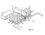
- FIG 2 an example of application of the present pick and place mechanism is schematically shown, in which the gripper arm with pliers is coupled to a production machine 39, from which each time a product 44 is removed by means of the pliers 2 and is placed onto a sheetlike storage means 42 according to an arbitrarily programmable matrix form and sequence.
- Said storage means comes from a pile I with storage means place on the frame 43 of the pick and place mechanism, which in the present case are empty, each time the lower storage means being supplied from the pile I to a place below the gripper arm with pliers 2.
- the pile I is lifted e.g. by means of a motor through a cam mechanism and a perpendicularly guiding member (not shown), in which for instance four tensile magnets are used, which grip below the lowest but one storage means. Thereafter the lowest storage means is placed on a guiding gutter.
- a further motor through a cam mechanism the storage means displaced from the pile I is displaced along the frame in the direction indicated by arrows.
- the great number of possibilities of the present stoke accelerating mechanism is obtained as to speed, accuracy and adjustment by the step by step motor drive controlled by a microprocessor.
Landscapes
- Engineering & Computer Science (AREA)
- Mechanical Engineering (AREA)
- Robotics (AREA)
- General Engineering & Computer Science (AREA)
- Manipulator (AREA)
- Preliminary Treatment Of Fibers (AREA)
- Cleaning And De-Greasing Of Metallic Materials By Chemical Methods (AREA)
- Specific Conveyance Elements (AREA)
Claims (12)
Priority Applications (3)
| Application Number | Priority Date | Filing Date | Title |
|---|---|---|---|
| EP82200999A EP0100794B1 (de) | 1982-08-09 | 1982-08-09 | Aufnahme- und Setzeinheit mit automatisch kontrolliertem Arm mit Greifer |
| AT82200999T ATE27593T1 (de) | 1982-08-09 | 1982-08-09 | Aufnahme- und setzeinheit mit automatisch kontrolliertem arm mit greifer. |
| DE8282200999T DE3276481D1 (en) | 1982-08-09 | 1982-08-09 | Pick and place unit having automatical controllable arm with gripper |
Applications Claiming Priority (1)
| Application Number | Priority Date | Filing Date | Title |
|---|---|---|---|
| EP82200999A EP0100794B1 (de) | 1982-08-09 | 1982-08-09 | Aufnahme- und Setzeinheit mit automatisch kontrolliertem Arm mit Greifer |
Publications (2)
| Publication Number | Publication Date |
|---|---|
| EP0100794A1 EP0100794A1 (de) | 1984-02-22 |
| EP0100794B1 true EP0100794B1 (de) | 1987-06-03 |
Family
ID=8189510
Family Applications (1)
| Application Number | Title | Priority Date | Filing Date |
|---|---|---|---|
| EP82200999A Expired EP0100794B1 (de) | 1982-08-09 | 1982-08-09 | Aufnahme- und Setzeinheit mit automatisch kontrolliertem Arm mit Greifer |
Country Status (3)
| Country | Link |
|---|---|
| EP (1) | EP0100794B1 (de) |
| AT (1) | ATE27593T1 (de) |
| DE (1) | DE3276481D1 (de) |
Families Citing this family (2)
| Publication number | Priority date | Publication date | Assignee | Title |
|---|---|---|---|---|
| FR2625414B1 (fr) * | 1987-12-31 | 1990-06-01 | Unicor Union Cooperatives Agri | Melange d'ingredients nutritionnels pour l'alimentation des ruminants |
| FR2735760B1 (fr) * | 1995-06-21 | 1997-08-22 | Tech D Automatismes Et D Ensem | Dispositif de transfert de pieces d'un point a un autre suivant un trajet simple en u renverse |
Citations (1)
| Publication number | Priority date | Publication date | Assignee | Title |
|---|---|---|---|---|
| GB191001038A (en) * | 1910-01-14 | 1910-06-23 | British Thomson Houston Co Ltd | Improvements in and relating to Apparatus for Automatically Transferring Articles to and from a Machine in which they receive Treatment. |
Family Cites Families (1)
| Publication number | Priority date | Publication date | Assignee | Title |
|---|---|---|---|---|
| US3884363A (en) * | 1973-09-13 | 1975-05-20 | Bendix Corp | Programmable universal transfer device |
-
1982
- 1982-08-09 DE DE8282200999T patent/DE3276481D1/de not_active Expired
- 1982-08-09 AT AT82200999T patent/ATE27593T1/de active
- 1982-08-09 EP EP82200999A patent/EP0100794B1/de not_active Expired
Patent Citations (1)
| Publication number | Priority date | Publication date | Assignee | Title |
|---|---|---|---|---|
| GB191001038A (en) * | 1910-01-14 | 1910-06-23 | British Thomson Houston Co Ltd | Improvements in and relating to Apparatus for Automatically Transferring Articles to and from a Machine in which they receive Treatment. |
Also Published As
| Publication number | Publication date |
|---|---|
| EP0100794A1 (de) | 1984-02-22 |
| ATE27593T1 (de) | 1987-06-15 |
| DE3276481D1 (en) | 1987-07-09 |
Similar Documents
| Publication | Publication Date | Title |
|---|---|---|
| US10873000B2 (en) | Method and automatic production plant for printing on photovoltaic cells | |
| US5094282A (en) | Lumber processing apparatus | |
| EP0302542B1 (de) | Vorrichtung zum Ein- und Ausführen von Trägern in einem Positionierungsgerät und Wähleinrichtung zum Anwenden in einer derartigen Vorrichtung | |
| JP2024509970A (ja) | 貨物棚移しを識別可能なロボットを利用する貨物仕分けシステムおよび仕分け方法 | |
| US5193973A (en) | Palletizing system | |
| US4565478A (en) | Materials handling device | |
| JPS6327322A (ja) | 磁気で捕捉可能な材料でつくられた容器をパレツト上に積むための装置 | |
| EP0416555B1 (de) | Bestückungsvorrichtung für elektrische Bauelemente mit zwei Trägern für die Zuführung von drei oder mehr Bestückungstischen | |
| JP4751664B2 (ja) | 空袋供給装置 | |
| US20220055834A1 (en) | A storage unit for smt supplies | |
| EP0265985B1 (de) | Vorrichtung zum Greifen und Setzen von Bauteilen | |
| EP0100794A1 (de) | Aufnahme- und Setzeinheit mit automatisch kontrolliertem Arm mit Greifer | |
| CN211846302U (zh) | 一种传送识别装置 | |
| US4303365A (en) | Continuous chain stacker/unstacker | |
| CN219899150U (zh) | 物品分拣装置 | |
| CN213678913U (zh) | 钢筋网码垛装置以及钢筋网生产设备 | |
| CN223479509U (zh) | 一种生产线盒箱数据识读及交叉关联系统 | |
| CN223779471U (zh) | 适用于自动化生产线的拆堆垛机构 | |
| USRE31858E (en) | Continuous chain stacker/unstacker | |
| SU1678579A1 (ru) | Транспортно-накопительное устройство | |
| SU1206053A1 (ru) | Накопитель | |
| US4343583A (en) | Continuous chain stacker/unstacker | |
| SU910231A1 (ru) | Устройство дл контрол и сортировки линз | |
| EP1088617A1 (de) | System zum Bewegen eines Objektes und Verfahren zu dessen Verwendung | |
| JPS5953177A (ja) | 産業ロボツトシステム |
Legal Events
| Date | Code | Title | Description |
|---|---|---|---|
| PUAI | Public reference made under article 153(3) epc to a published international application that has entered the european phase |
Free format text: ORIGINAL CODE: 0009012 |
|
| 17P | Request for examination filed |
Effective date: 19830726 |
|
| AK | Designated contracting states |
Designated state(s): AT BE CH DE FR GB IT LI LU NL SE |
|
| GRAA | (expected) grant |
Free format text: ORIGINAL CODE: 0009210 |
|
| AK | Designated contracting states |
Kind code of ref document: B1 Designated state(s): AT BE CH DE FR GB IT LI LU NL SE |
|
| PG25 | Lapsed in a contracting state [announced via postgrant information from national office to epo] |
Ref country code: LI Effective date: 19870603 Ref country code: IT Free format text: LAPSE BECAUSE OF FAILURE TO SUBMIT A TRANSLATION OF THE DESCRIPTION OR TO PAY THE FEE WITHIN THE PRESCRIBED TIME-LIMIT;WARNING: LAPSES OF ITALIAN PATENTS WITH EFFECTIVE DATE BEFORE 2007 MAY HAVE OCCURRED AT ANY TIME BEFORE 2007. THE CORRECT EFFECTIVE DATE MAY BE DIFFERENT FROM THE ONE RECORDED. Effective date: 19870603 Ref country code: FR Free format text: THE PATENT HAS BEEN ANNULLED BY A DECISION OF A NATIONAL AUTHORITY Effective date: 19870603 Ref country code: CH Effective date: 19870603 Ref country code: BE Effective date: 19870603 Ref country code: AT Effective date: 19870603 |
|
| REF | Corresponds to: |
Ref document number: 27593 Country of ref document: AT Date of ref document: 19870615 Kind code of ref document: T |
|
| PG25 | Lapsed in a contracting state [announced via postgrant information from national office to epo] |
Ref country code: SE Effective date: 19870630 |
|
| REF | Corresponds to: |
Ref document number: 3276481 Country of ref document: DE Date of ref document: 19870709 |
|
| PG25 | Lapsed in a contracting state [announced via postgrant information from national office to epo] |
Ref country code: LU Free format text: LAPSE BECAUSE OF NON-PAYMENT OF DUE FEES Effective date: 19870831 |
|
| REG | Reference to a national code |
Ref country code: CH Ref legal event code: PL |
|
| EN | Fr: translation not filed | ||
| PLBE | No opposition filed within time limit |
Free format text: ORIGINAL CODE: 0009261 |
|
| STAA | Information on the status of an ep patent application or granted ep patent |
Free format text: STATUS: NO OPPOSITION FILED WITHIN TIME LIMIT |
|
| GBPC | Gb: european patent ceased through non-payment of renewal fee | ||
| 26N | No opposition filed | ||
| PG25 | Lapsed in a contracting state [announced via postgrant information from national office to epo] |
Ref country code: GB Free format text: LAPSE BECAUSE OF NON-PAYMENT OF DUE FEES Effective date: 19881122 |
|
| PGFP | Annual fee paid to national office [announced via postgrant information from national office to epo] |
Ref country code: NL Payment date: 19930831 Year of fee payment: 12 |
|
| PGFP | Annual fee paid to national office [announced via postgrant information from national office to epo] |
Ref country code: DE Payment date: 19940630 Year of fee payment: 13 |
|
| PG25 | Lapsed in a contracting state [announced via postgrant information from national office to epo] |
Ref country code: NL Effective date: 19950301 |
|
| NLV4 | Nl: lapsed or anulled due to non-payment of the annual fee | ||
| PG25 | Lapsed in a contracting state [announced via postgrant information from national office to epo] |
Ref country code: DE Effective date: 19960501 |