EP0100754A2 - Method for making a spectacles resilient hinge - Google Patents
Method for making a spectacles resilient hinge Download PDFInfo
- Publication number
- EP0100754A2 EP0100754A2 EP83830154A EP83830154A EP0100754A2 EP 0100754 A2 EP0100754 A2 EP 0100754A2 EP 83830154 A EP83830154 A EP 83830154A EP 83830154 A EP83830154 A EP 83830154A EP 0100754 A2 EP0100754 A2 EP 0100754A2
- Authority
- EP
- European Patent Office
- Prior art keywords
- spectacles
- effective
- arm
- members
- hinge
- Prior art date
- Legal status (The legal status is an assumption and is not a legal conclusion. Google has not performed a legal analysis and makes no representation as to the accuracy of the status listed.)
- Granted
Links
- 238000000034 method Methods 0.000 title claims abstract description 35
- 239000000463 material Substances 0.000 claims abstract description 22
- 239000007769 metal material Substances 0.000 claims abstract description 6
- 238000011282 treatment Methods 0.000 claims abstract description 3
- 230000008878 coupling Effects 0.000 claims description 9
- 238000010168 coupling process Methods 0.000 claims description 9
- 238000005859 coupling reaction Methods 0.000 claims description 9
- 239000002184 metal Substances 0.000 claims description 5
- 229910052751 metal Inorganic materials 0.000 claims description 5
- 238000004873 anchoring Methods 0.000 claims description 4
- MOFOBJHOKRNACT-UHFFFAOYSA-N nickel silver Chemical compound [Ni].[Ag] MOFOBJHOKRNACT-UHFFFAOYSA-N 0.000 claims description 3
- 239000010956 nickel silver Substances 0.000 claims description 3
- 238000004026 adhesive bonding Methods 0.000 claims description 2
- 238000005452 bending Methods 0.000 claims description 2
- 239000002991 molded plastic Substances 0.000 claims description 2
- 230000008569 process Effects 0.000 claims description 2
- 239000010935 stainless steel Substances 0.000 claims description 2
- 229910001220 stainless steel Inorganic materials 0.000 claims description 2
- 238000006243 chemical reaction Methods 0.000 description 4
- 239000004033 plastic Substances 0.000 description 4
- 229920003023 plastic Polymers 0.000 description 4
- 229910000831 Steel Inorganic materials 0.000 description 3
- 239000010959 steel Substances 0.000 description 3
- 238000012986 modification Methods 0.000 description 2
- 230000004048 modification Effects 0.000 description 2
- 238000012545 processing Methods 0.000 description 2
- 235000001674 Agaricus brunnescens Nutrition 0.000 description 1
- 229910000760 Hardened steel Inorganic materials 0.000 description 1
- 230000009471 action Effects 0.000 description 1
- 238000013459 approach Methods 0.000 description 1
- 238000007796 conventional method Methods 0.000 description 1
- 230000000694 effects Effects 0.000 description 1
- 230000013011 mating Effects 0.000 description 1
- 238000007789 sealing Methods 0.000 description 1
- 238000010008 shearing Methods 0.000 description 1
- 238000004381 surface treatment Methods 0.000 description 1
Images

Classifications
-
- G—PHYSICS
- G02—OPTICS
- G02C—SPECTACLES; SUNGLASSES OR GOGGLES INSOFAR AS THEY HAVE THE SAME FEATURES AS SPECTACLES; CONTACT LENSES
- G02C5/00—Constructions of non-optical parts
- G02C5/22—Hinges
- G02C5/2218—Resilient hinges
- G02C5/2227—Resilient hinges comprising a fixed hinge member and a coil spring
-
- G—PHYSICS
- G02—OPTICS
- G02C—SPECTACLES; SUNGLASSES OR GOGGLES INSOFAR AS THEY HAVE THE SAME FEATURES AS SPECTACLES; CONTACT LENSES
- G02C2200/00—Generic mechanical aspects applicable to one or more of the groups G02C1/00 - G02C5/00 and G02C9/00 - G02C13/00 and their subgroups
- G02C2200/26—Coil spring pushed upon actuation
-
- Y—GENERAL TAGGING OF NEW TECHNOLOGICAL DEVELOPMENTS; GENERAL TAGGING OF CROSS-SECTIONAL TECHNOLOGIES SPANNING OVER SEVERAL SECTIONS OF THE IPC; TECHNICAL SUBJECTS COVERED BY FORMER USPC CROSS-REFERENCE ART COLLECTIONS [XRACs] AND DIGESTS
- Y10—TECHNICAL SUBJECTS COVERED BY FORMER USPC
- Y10T—TECHNICAL SUBJECTS COVERED BY FORMER US CLASSIFICATION
- Y10T29/00—Metal working
- Y10T29/24—Hinge making or assembling
-
- Y—GENERAL TAGGING OF NEW TECHNOLOGICAL DEVELOPMENTS; GENERAL TAGGING OF CROSS-SECTIONAL TECHNOLOGIES SPANNING OVER SEVERAL SECTIONS OF THE IPC; TECHNICAL SUBJECTS COVERED BY FORMER USPC CROSS-REFERENCE ART COLLECTIONS [XRACs] AND DIGESTS
- Y10—TECHNICAL SUBJECTS COVERED BY FORMER USPC
- Y10T—TECHNICAL SUBJECTS COVERED BY FORMER US CLASSIFICATION
- Y10T29/00—Metal working
- Y10T29/31—Spectacle-frame making
-
- Y—GENERAL TAGGING OF NEW TECHNOLOGICAL DEVELOPMENTS; GENERAL TAGGING OF CROSS-SECTIONAL TECHNOLOGIES SPANNING OVER SEVERAL SECTIONS OF THE IPC; TECHNICAL SUBJECTS COVERED BY FORMER USPC CROSS-REFERENCE ART COLLECTIONS [XRACs] AND DIGESTS
- Y10—TECHNICAL SUBJECTS COVERED BY FORMER USPC
- Y10T—TECHNICAL SUBJECTS COVERED BY FORMER US CLASSIFICATION
- Y10T29/00—Metal working
- Y10T29/49—Method of mechanical manufacture
- Y10T29/49826—Assembling or joining
- Y10T29/4984—Retaining clearance for motion between assembled parts
- Y10T29/49844—Through resilient media
Definitions
- the present invention relates to a method for making resilient hinges for spectacles.
- resilient hinges are known of the so-called double action type, i.e effective to provide a resilient reaction both in the arm opening step(that is with the spectacles arm parallel to one another during the use) and im the arm closure step, with the spectacles arm in a closed condition at rest.
- the operating principle of the mentioned hinges is that of the resilient reaction provided by a cam profile thereon a ball member is caused to slide as biassed by a spring.
- cam member is generally made starting from hardened steel or a sinterized material.
- the pieces made starting from the mentioned materials are to be suitably processed in order to prevent said pieces from being quickly oxidated.
- the protecting covering layer may be obtained only by carrying out determin- ea processing steps(for example sealing of the steel cam member to the front of the spectacles frame) and, accordimgly, other portions of the spectacles are affected, with consequent increased costs.
- a steel material may be hardly machined by tools, particularly as the conventional method for making not resilient hinges is used.
- spectacles are provided with nickel silver hinges so shaped as to allow for the spectacles arm to be adjusted in its slant, in order to fit the spectacles to the user face.
- the steel cam member is made im a single piece with the spectacles front portioa, thereby it may be hardly subjected to modifications.
- im plastics spectacldes the anchoring blaae embedded in the spectacle front portion, acts as a cutting blade susceptible to cut through the spectacles as the latter are stressed duriag the use or because or temperature variations.
- the cam member is arranged at the outermost end of the spectacles frame,jointly to the front portion acting as an insert,thereby facilitating possible breakages.
- the task of the present invention is that of overcoming the thereinabove mentioned drawbacks by providing a method for making spectacles resilient hinges which may be carried out easily and at a reduced cost.
- Another object of the present invention is to provide such a method which is effective to afford the possibility of obtaining such a spectacles hinge which is so designed as to be easily adjustable in order to properly fit the spectacles to the wearer face.
- Yet another object of the present invention is to provide such a method which affords the possibility of making resilient spectacles hinges applicable between the spectacles front portion and related arm, in a simple way and without any danger of spoiling the spectacles frame.
- Yet another object or the present invention is to provide such a method affording the possibility of making several types of spectacles resilient hinges.
- Yet another object of the present invention is to provide such a spectacles resilient hinge therein the opening dead point may be easily adjusted in order to reset the arms to their parallelism relationship.
- Yet another object of the present invention is to provide such a method thereby reduced size resilient hinges may be produced,effective to be applied on light and thin frames.
- a method for making spectacles resilient hinges,of the cam profile and spring biassed ball type comprises the steps of making a hinge by using conventional materials and Treatments and applying, on the edge of said hinge provided for contacting and biassing said ball,one or more cup members, mane of a hard material, and effective to provide said cam profile.
- the method for making resilient hinges for spectacles comprises the step of providing a small plate member 1, which is essentially provided with an edge 2 thereto shaped members maae of a hard metal material may be firmly coupled as well as a portion 3,also suitably shaped, effective to allow for said members to be locked either on the front portion or on an arm of the spectacles frame.
- the mentioned plate may be obtained either by cutting a suitable cross-section sectional member 4 or by shearing a blade member 5, made of an easily machinable material such as nickel silver.
- That same plate will be obviously subjeted to suitable conventional processing steps, in order to form therein a portion b provided with a throughgoing hole 7,effective to be rotatively coupled,through a threaded member 8,to the two legs of a bifurcated member 9 forming the spectacles arm end portion.
- two counterbores 10 effective to hold corresponding cup members, made of stainless steel or of a sinterized material, which may be provided with a spherical 11 or not spherical surface 11',or with two flat converging surfaces 11" depending on the requirements.
- the counterbore 10 therein the outer cup is housed may be threaded in such a way as to allow for the related cup, also threaded on its cylindrical outer surface, to vary the position of the spring biassed ball,in such a way as to provide different angular positions of the spectacles arm at the opening dead point.
- the mentioned counterbores,providing holding seats for said cups 11, are preferably made on slanted surfaces in order to allow for the arms to be set in a parallel relationship,as well as for providing gradual resilient reactions, during the arm opening and closing movements,thereby allowing for the outer cup to act as an opening stroke stop member.
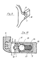
- the anchoring of the individual cup members in their seats may be obtained,as it is schematically illustrated in fig.7,by using mushroom cup members and deforming the housing of the stem 12,or by caulking the edge 13 of the mentioned counterbores on the cup convex portion,or by bending the edge of said counterbores on an abutment member as perime trical- ly formed with respect to the cup,all along the extension 14 thereof, or at a single sector 14.
- anchoring of said cups in their seats may also be obtained by other like methods, such as glueing methods and the like.
- the mentioned cups engage with a ball member 15, biassed by a spring 16, which are housed in a suitable cylindrical seat 17, as formed along the axis of the rod 18 and being open at the bifurcated portion 9 forming the end portion of said rod or arm.
- cam profile,obtained by means of two cups is merely a preferred embodiment and that it may also be obtained starting from different mating members, or it may be made of a suitably shaped single piece of a hard material.
- the above cam member supporting plate may be also formed directly in the spectacles frame (both arm portion and front portion), as it is shown in fig.13,preferably in metal material frames, but also in molded plastics material frames, provided that the latter be provided with suitable hardness characteristics.
- hinge assembly may also be made in a reversed arrangement, that is with the cam profile applied on the arm and the ball-spring assembly located in the portion rigid with the spectacles front portion.
- the hinge is processes as a conventional hinge and it becomes "resilient" at the last stage,as the shape thereof has been already defined,since the cup members may be applied during a last assembling step, with the hinges already applied to the spectacles frame.
Landscapes
- Physics & Mathematics (AREA)
- Health & Medical Sciences (AREA)
- General Physics & Mathematics (AREA)
- Ophthalmology & Optometry (AREA)
- Optics & Photonics (AREA)
- Eyeglasses (AREA)
- Laminated Bodies (AREA)
- Pivots And Pivotal Connections (AREA)
Abstract
Description
- The present invention relates to a method for making resilient hinges for spectacles.
- As it is well known,resilient hinges for spectacles frames are presently commercially available which allow for the spectacles arms to be resiliently gradually biassed with respect to the spectacles frame front portion owing to the provision of resilient biassing means acting on a suitably shaped cam profile.
- In particular resilient hinges are known of the so-called double action type, i.e effective to provide a resilient reaction both in the arm opening step(that is with the spectacles arm parallel to one another during the use) and im the arm closure step, with the spectacles arm in a closed condition at rest.
- The operating principle of the mentioned hinges is that of the resilient reaction provided by a cam profile thereon a ball member is caused to slide as biassed by a spring.
- In order to obtaim an efficient and proper resilient reaction it is required that the cam member cooperating with said ball member,be made from a high hardness material.
- Infact,if the hardness of said material is a poor one,the ball member would be susceptible to penetrate into the cam surface, there by impairing the cam effect thereor, because of wear.
- Thus the mentioned cam member is generally made starting from hardened steel or a sinterized material.
- On the other hand, these materials are affected by practical drawbacks, since they are necessarily to be subjected to protecting tree tmentsp; moreover they may be hardly processed to obtain the desired shapes and coupling to other components of the frame.
- More specifically, as thereinabove stated, the pieces made starting from the mentioned materials are to be suitably processed in order to prevent said pieces from being quickly oxidated.
- The protecting covering layer, on the other hand,may be obtained only by carrying out determin- ea processing steps(for example sealing of the steel cam member to the front of the spectacles frame) and, accordimgly, other portions of the spectacles are affected, with consequent increased costs.
- Moreover,a steel material may be hardly machined by tools, particularly as the conventional method for making not resilient hinges is used.
- It should also be noted that presently available spectacles are provided with nickel silver hinges so shaped as to allow for the spectacles arm to be adjusted in its slant, in order to fit the spectacles to the user face.
- On the other hand, the steel cam member is made im a single piece with the spectacles front portioa, thereby it may be hardly subjected to modifications.
- With respect to the applying ana coupling features, it should be noted that, im plastics spectacldes, the anchoring blaae embedded in the spectacle front portion, acts as a cutting blade susceptible to cut through the spectacles as the latter are stressed duriag the use or because or temperature variations.
- Moreover,because of contingent requirements, . that is because of constructional reasons,the cam member is arranged at the outermost end of the spectacles frame,jointly to the front portion acting as an insert,thereby facilitating possible breakages.
- Accordingly, the task of the present invention is that of overcoming the thereinabove mentioned drawbacks by providing a method for making spectacles resilient hinges which may be carried out easily and at a reduced cost.
- Within that task,it is a main object of the present invention to provide such a method therein there is eliminated the need of carrying out protecting surface treatments om the produced hinges.
- Another object of the present invention is to provide such a method which is effective to afford the possibility of obtaining such a spectacles hinge which is so designed as to be easily adjustable in order to properly fit the spectacles to the wearer face.
- Yet another object of the present invention is to provide such a method which affords the possibility of making resilient spectacles hinges applicable between the spectacles front portion and related arm, in a simple way and without any danger of spoiling the spectacles frame.
- Yet another object or the present invention is to provide such a method affording the possibility of making several types of spectacles resilient hinges.
- Yet another object of the present invention is to provide such a spectacles resilient hinge therein the opening dead point may be easily adjusted in order to reset the arms to their parallelism relationship.
- Yet another object of the present invention is to provide such a method thereby reduced size resilient hinges may be produced,effective to be applied on light and thin frames.
- According to one aspect of the present invention the above task and objects, as well-as yet other objects which will become more apparent hereinafter are achieved by a method for making spectacles resilient hinges,of the cam profile and spring biassed ball type,characterized in that it comprises the steps of making a hinge by using conventional materials and Treatments and applying, on the edge of said hinge provided for contacting and biassing said ball,one or more cup members, mane of a hard material, and effective to provide said cam profile.
- Further characteristics and advantages of the method for making spectacles resilient hinges according to the present invention will become more apparent thereinafter from the following detailed description of some embodiments thereof, with reference to the accompanying drawings,where:
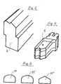
- fig.l illustrates the portion of a hinge, for plastics material spectacles frame,provded for housing the hard metal cup members;
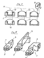
- fgs. 2 and 3 illustrate two bifurcated members,respectively of a metal material, in single piece with the arm, and of a plastics material, effective to be rotatively coupled to the mentioned hinge portion;
- fig.4 illustrate a sectional member substantially reproducing the contour of the mentioned hinge portion;
- fig. 5 illustrate a plate member therefrom the hinge portion of fig.1 may be obtained;
- fig.b illustrates preferred embodiments of the hard metal cup members;
- fig.7 illustratively shows a possible procedure for coupling the cup members and hinge;
- fig. 8 illustrates some embodiments or a hinge provided for metal frames,effective to house the mentioned cup members;
- fig.9 illustrates the coupling between a spectacles front portion and a plastics material arm, obtained by means of a hinge produced by the subject method;
- fig. 10 is a horizontal cross-sectional view of the mentioned coupling;
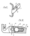
- fig. 11 illustrates a further coupling between a spectacles front portion and arm, in a metal frame;
- fig.12 is a horizontal cross-sectional view of the coupling shown in fig.11; and
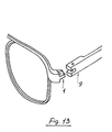
- rig.13 illustrates a resilient spectacles hinge according to the present invention, therein the hinge portion rigid with the frame is made in a single piece with the spectacles frame itself.
- With reference to the figures of the accompanying drawings, the method for making resilient hinges for spectacles according to the present invention comprises the step of providing a
small plate member 1, which is essentially provided with anedge 2 thereto shaped members maae of a hard metal material may be firmly coupled as well as aportion 3,also suitably shaped, effective to allow for said members to be locked either on the front portion or on an arm of the spectacles frame. - More specifically, the mentioned plate may be obtained either by cutting a suitable cross-section
sectional member 4 or by shearing ablade member 5, made of an easily machinable material such as nickel silver. - That same plate will be obviously subjeted to suitable conventional processing steps, in order to form therein a portion b provided with a
throughgoing hole 7,effective to be rotatively coupled,through a threadedmember 8,to the two legs of a bifurcatedmember 9 forming the spectacles arm end portion. - On the
edge 2 of the mentioned plate there are formed twocounterbores 10, effective to hold corresponding cup members, made of stainless steel or of a sinterized material, which may be provided with a spherical 11 or not spherical surface 11',or with twoflat converging surfaces 11" depending on the requirements. - spectifically, the
counterbore 10 therein the outer cup is housed may be threaded in such a way as to allow for the related cup, also threaded on its cylindrical outer surface, to vary the position of the spring biassed ball,in such a way as to provide different angular positions of the spectacles arm at the opening dead point. - In this connection it should be noted that the mentioned counterbores,providing holding seats for said
cups 11,are preferably made on slanted surfaces in order to allow for the arms to be set in a parallel relationship,as well as for providing gradual resilient reactions, during the arm opening and closing movements,thereby allowing for the outer cup to act as an opening stroke stop member. - The anchoring of the individual cup members in their seats may be obtained,as it is schematically illustrated in fig.7,by using mushroom cup members and deforming the housing of the
stem 12,or by caulking theedge 13 of the mentioned counterbores on the cup convex portion,or by bending the edge of said counterbores on an abutment member as perime trical- ly formed with respect to the cup,all along theextension 14 thereof, or at asingle sector 14. - It should also be noted that the anchoring of said cups in their seats may also be obtained by other like methods, such as glueing methods and the like.
- The mentioned cups engage with a
ball member 15, biassed by aspring 16, which are housed in a suitablecylindrical seat 17, as formed along the axis of therod 18 and being open at the bifurcatedportion 9 forming the end portion of said rod or arm. - It shorld also be pointed out that the cam profile,obtained by means of two cups,is merely a preferred embodiment and that it may also be obtained starting from different mating members, or it may be made of a suitably shaped single piece of a hard material.
- In this connection it should also be noted that, since the contacting surfaces of the ball and cam members are in actual practice both of spherical configuration, the friction therebetween is reduced to a minimum, there by providing even and precise movements of the arms.
- In particular,the above cam member supporting plate may be also formed directly in the spectacles frame (both arm portion and front portion), as it is shown in fig.13,preferably in metal material frames, but also in molded plastics material frames, provided that the latter be provided with suitable hardness characteristics.
- The latter approach is made possible by the fact that the resilient reation force is supported by the two cup members, without affecting other portions of the hinge.
- Moreover the hinge assembly may also be made in a reversed arrangement, that is with the cam profile applied on the arm and the ball-spring assembly located in the portion rigid with the spectacles front portion.
- From the above disclosure and the figures of the accompanying drawings there are self-evident the great constructional simplcity and the possibility of producing a broad range of spectacles frames characterizing the method for making resilient hinges for spectacles according to the present invention.
- Infact,in the method,the hinge is processes as a conventional hinge and it becomes "resilient" at the last stage,as the shape thereof has been already defined,since the cup members may be applied during a last assembling step, with the hinges already applied to the spectacles frame.
- In other words,before applying the screw for coupling pivotally the spectacles arm and front portion,it will be possible to affix the cup members by means of one of the methods thereinabove illustrated.
- While the subject method has been disclosed and illustrated by way of an indicative and not limitative example, it will be clear that it is susceptible to several modifications and variations all thereof are included in the spirit and scope or the invention,as defined in the accompanying claims.
Claims (10)
Priority Applications (1)
| Application Number | Priority Date | Filing Date | Title |
|---|---|---|---|
| AT83830154T ATE24972T1 (en) | 1982-07-30 | 1983-07-25 | PROCESS FOR MAKING AN ELASTIC EYEGLASSES HINGE. |
Applications Claiming Priority (2)
| Application Number | Priority Date | Filing Date | Title |
|---|---|---|---|
| IT22691/82A IT1153157B (en) | 1982-07-30 | 1982-07-30 | PROCEDURE FOR THE MANUFACTURE OF AN ELASTIC HINGE FOR GLASSES |
| IT2269182 | 1982-07-30 |
Publications (3)
| Publication Number | Publication Date |
|---|---|
| EP0100754A2 true EP0100754A2 (en) | 1984-02-15 |
| EP0100754A3 EP0100754A3 (en) | 1984-08-29 |
| EP0100754B1 EP0100754B1 (en) | 1987-01-14 |
Family
ID=11199290
Family Applications (1)
| Application Number | Title | Priority Date | Filing Date |
|---|---|---|---|
| EP83830154A Expired EP0100754B1 (en) | 1982-07-30 | 1983-07-25 | Method for making a spectacles resilient hinge |
Country Status (6)
| Country | Link |
|---|---|
| US (1) | US4570289A (en) |
| EP (1) | EP0100754B1 (en) |
| AT (1) | ATE24972T1 (en) |
| CA (1) | CA1212530A (en) |
| DE (1) | DE3369200D1 (en) |
| IT (1) | IT1153157B (en) |
Cited By (7)
| Publication number | Priority date | Publication date | Assignee | Title |
|---|---|---|---|---|
| FR2631712A1 (en) * | 1988-05-17 | 1989-11-24 | Ange Cajigas | Spectacles hinge |
| WO1996034308A1 (en) * | 1995-04-27 | 1996-10-31 | Obe-Werk Ohnmacht & Baumgärtner Gmbh & Co. Kg | Spring hinge |
| WO1997022902A1 (en) * | 1995-12-20 | 1997-06-26 | OBE OHNMACHT & BAUMGäRTNER GMBH & CO. KG | Method of producing a spectacles hinge |
| EP0992831A1 (en) * | 1998-10-09 | 2000-04-12 | Ideal S.R.L. | Flexible ear-piece for eyeglasses, of the type with ball elastic yielding mechanism |
| EP1079256A1 (en) * | 1999-08-24 | 2001-02-28 | Raymond Chu Optical Company Limited | Double action titanium spring hinge for eyewear and sunglasses |
| ITTO20090686A1 (en) * | 2009-09-07 | 2011-03-08 | Cesare Massacesi | FRAME FOR GLASSES |
| ITUD20110080A1 (en) * | 2011-06-06 | 2012-12-07 | Visottica Ind S P A Con Unic O Socio | SINGLE COMPONENT HINGE ELEMENT AND RELATED PRODUCTION METHOD |
Families Citing this family (8)
| Publication number | Priority date | Publication date | Assignee | Title |
|---|---|---|---|---|
| US5187504A (en) * | 1991-05-10 | 1993-02-16 | David Huang | Eyeglass frame having hollow adjustable connector |
| IT1262254B (en) * | 1993-12-17 | 1996-06-19 | Euroframes Srl | HINGE FOR CONNECTION BETWEEN BAR AND FRAME IN A PAIR OF GLASSES |
| US5730610A (en) * | 1996-03-22 | 1998-03-24 | Berg Technology, Inc. | Memory card connector having a spring restrained activator rod and folding push button mechanism |
| IT1293363B1 (en) * | 1997-05-29 | 1999-02-25 | Killer Loop Eyewear Srl | INTERCONNECTION DEVICE, PARTICULARLY FOR GLASSES |
| US6553624B1 (en) * | 1998-08-17 | 2003-04-29 | Tsung-Lung Lin | Hinge device for cabinets with prevention of automatic opening of doors |
| USD682924S1 (en) * | 2011-09-30 | 2013-05-21 | Chuen Fung Spectacles Services Manufactory Limited | Spring hinge |
| ITTV20130051A1 (en) * | 2013-04-11 | 2014-10-12 | Matrix Srl | HINGE FOR EYEWEAR FRAMES |
| USD776752S1 (en) * | 2015-06-24 | 2017-01-17 | Wen-Tse HUANG | Eyeglass temple |
Family Cites Families (13)
| Publication number | Priority date | Publication date | Assignee | Title |
|---|---|---|---|---|
| US1395593A (en) * | 1921-05-11 | 1921-11-01 | John M Oknianski | Hinge |
| US1494139A (en) * | 1921-12-16 | 1924-05-13 | Clara W Simon | Hinge |
| US1708202A (en) * | 1922-07-03 | 1929-04-09 | Bausch & Lomb | Method of making hinges |
| US2098921A (en) * | 1935-05-08 | 1937-11-09 | Mandaville Gurney Lee | Spectacle joint |
| US2874609A (en) * | 1955-03-02 | 1959-02-24 | Ducati Marcello | Mounting arrangement for spectacle side pieces |
| US3064530A (en) * | 1958-04-30 | 1962-11-20 | Meccanoptica S P A | Arrangement for adjusting the slope of spectacle rims with reference to the sides |
| CH506081A (en) * | 1969-01-22 | 1971-04-15 | Leonardo Meccanoptica | Elastic hinge for eyeglass frames |
| FR2178828B1 (en) * | 1972-04-06 | 1976-08-06 | Guillet Henri | |
| IT995606B (en) * | 1973-10-04 | 1975-11-20 | Leonardo Meccanoptica | HINGE FOR THE JOINTED CONNECTION BETWEEN THE FRAME AND SIDE BARS OF GLASSES |
| FR2298116A1 (en) * | 1975-01-17 | 1976-08-13 | Herda Henri | Spectacle mounts with hinge - has cam and cavity configuration the latter having a projecting elastic system |
| CH622623A5 (en) * | 1978-05-30 | 1981-04-15 | Nationale Sa | |
| DE2948113A1 (en) * | 1979-11-29 | 1981-06-04 | Fa. Ferdinand Menrad, 7070 Schwäbisch Gmünd | Sprung spectacle frame hinge - has bores between hinge eyes on side for springs loading balls to engage recesses in matching eyes on frame |
| CH635444A5 (en) * | 1980-03-26 | 1983-03-31 | Nationale Sa | GLASSES HINGE. |
-
1982
- 1982-07-30 IT IT22691/82A patent/IT1153157B/en active
-
1983
- 1983-07-25 EP EP83830154A patent/EP0100754B1/en not_active Expired
- 1983-07-25 AT AT83830154T patent/ATE24972T1/en not_active IP Right Cessation
- 1983-07-25 DE DE8383830154T patent/DE3369200D1/en not_active Expired
- 1983-07-25 US US06/516,885 patent/US4570289A/en not_active Expired - Lifetime
- 1983-07-27 CA CA000433300A patent/CA1212530A/en not_active Expired
Cited By (8)
| Publication number | Priority date | Publication date | Assignee | Title |
|---|---|---|---|---|
| FR2631712A1 (en) * | 1988-05-17 | 1989-11-24 | Ange Cajigas | Spectacles hinge |
| WO1996034308A1 (en) * | 1995-04-27 | 1996-10-31 | Obe-Werk Ohnmacht & Baumgärtner Gmbh & Co. Kg | Spring hinge |
| WO1997022902A1 (en) * | 1995-12-20 | 1997-06-26 | OBE OHNMACHT & BAUMGäRTNER GMBH & CO. KG | Method of producing a spectacles hinge |
| US5797173A (en) * | 1995-12-20 | 1998-08-25 | Obe-Werk Ohnmacht & Baumgartner Gmbh & Co. Kg | Method of manufacturing a hinge for eyeglasses |
| EP0992831A1 (en) * | 1998-10-09 | 2000-04-12 | Ideal S.R.L. | Flexible ear-piece for eyeglasses, of the type with ball elastic yielding mechanism |
| EP1079256A1 (en) * | 1999-08-24 | 2001-02-28 | Raymond Chu Optical Company Limited | Double action titanium spring hinge for eyewear and sunglasses |
| ITTO20090686A1 (en) * | 2009-09-07 | 2011-03-08 | Cesare Massacesi | FRAME FOR GLASSES |
| ITUD20110080A1 (en) * | 2011-06-06 | 2012-12-07 | Visottica Ind S P A Con Unic O Socio | SINGLE COMPONENT HINGE ELEMENT AND RELATED PRODUCTION METHOD |
Also Published As
| Publication number | Publication date |
|---|---|
| ATE24972T1 (en) | 1987-01-15 |
| DE3369200D1 (en) | 1987-02-19 |
| IT8222691A0 (en) | 1982-07-30 |
| US4570289A (en) | 1986-02-18 |
| IT8222691A1 (en) | 1984-01-30 |
| IT1153157B (en) | 1987-01-14 |
| EP0100754B1 (en) | 1987-01-14 |
| CA1212530A (en) | 1986-10-14 |
| EP0100754A3 (en) | 1984-08-29 |
Similar Documents
| Publication | Publication Date | Title |
|---|---|---|
| EP0100754A2 (en) | Method for making a spectacles resilient hinge | |
| JPH0531128B2 (en) | ||
| US4305160A (en) | Detent controlled helmet shields | |
| US6916093B2 (en) | Elastic hinge having a radial stop against excessive opening | |
| JPH09509707A (en) | Rotating window operation machine | |
| JP2018017731A (en) | Exterior subassemblies for watches or watches or jewelry | |
| WO2006078693A2 (en) | Adjustable sized jewelry | |
| US4222148A (en) | Spectacle hinge | |
| US2806927A (en) | Switch blade | |
| JPH11504132A (en) | Elastic hinge | |
| US5579559A (en) | Bracelet clasp of the unfolding buckle type | |
| US6494030B2 (en) | Bracelet made from links | |
| US6000796A (en) | Slidably resilient hinge for eyeglass frames | |
| EP0235780B1 (en) | Hinge device, particularly for spectacle frames | |
| HK125596A (en) | Eyeglass frame including shape memory elements | |
| JPH05323241A (en) | Compression joints for glasses | |
| EP0039149A1 (en) | Link for jewellery | |
| KR20100035865A (en) | Earring of manufacture method thereof | |
| US6247810B1 (en) | Hinge for eyeglasses | |
| JP6688495B1 (en) | Trinkets | |
| US9402449B1 (en) | Fastener for angle-adjustable earring | |
| US3491444A (en) | Scissors and other cutting or shearing hand tools | |
| JP2001070017A (en) | Ring insertable from multiple-directionally | |
| US3166754A (en) | Temple hinges | |
| US4468871A (en) | Tap dancing shoe taps |
Legal Events
| Date | Code | Title | Description |
|---|---|---|---|
| PUAI | Public reference made under article 153(3) epc to a published international application that has entered the european phase |
Free format text: ORIGINAL CODE: 0009012 |
|
| AK | Designated contracting states |
Designated state(s): AT BE CH DE FR GB LI NL SE |
|
| PUAL | Search report despatched |
Free format text: ORIGINAL CODE: 0009013 |
|
| AK | Designated contracting states |
Designated state(s): AT BE CH DE FR GB LI NL SE |
|
| 17P | Request for examination filed |
Effective date: 19840703 |
|
| GRAA | (expected) grant |
Free format text: ORIGINAL CODE: 0009210 |
|
| AK | Designated contracting states |
Kind code of ref document: B1 Designated state(s): AT BE CH DE FR GB LI NL SE |
|
| PG25 | Lapsed in a contracting state [announced via postgrant information from national office to epo] |
Ref country code: NL Effective date: 19870114 Ref country code: LI Effective date: 19870114 Ref country code: CH Effective date: 19870114 Ref country code: BE Effective date: 19870114 Ref country code: AT Effective date: 19870114 |
|
| REF | Corresponds to: |
Ref document number: 24972 Country of ref document: AT Date of ref document: 19870115 Kind code of ref document: T |
|
| PG25 | Lapsed in a contracting state [announced via postgrant information from national office to epo] |
Ref country code: SE Effective date: 19870131 |
|
| REF | Corresponds to: |
Ref document number: 3369200 Country of ref document: DE Date of ref document: 19870219 |
|
| REG | Reference to a national code |
Ref country code: CH Ref legal event code: PL |
|
| ET | Fr: translation filed | ||
| NLV1 | Nl: lapsed or annulled due to failure to fulfill the requirements of art. 29p and 29m of the patents act | ||
| PLBE | No opposition filed within time limit |
Free format text: ORIGINAL CODE: 0009261 |
|
| STAA | Information on the status of an ep patent application or granted ep patent |
Free format text: STATUS: NO OPPOSITION FILED WITHIN TIME LIMIT |
|
| 26N | No opposition filed | ||
| PGFP | Annual fee paid to national office [announced via postgrant information from national office to epo] |
Ref country code: GB Payment date: 19920715 Year of fee payment: 10 |
|
| PGFP | Annual fee paid to national office [announced via postgrant information from national office to epo] |
Ref country code: DE Payment date: 19920716 Year of fee payment: 10 |
|
| PGFP | Annual fee paid to national office [announced via postgrant information from national office to epo] |
Ref country code: FR Payment date: 19920731 Year of fee payment: 10 |
|
| PG25 | Lapsed in a contracting state [announced via postgrant information from national office to epo] |
Ref country code: GB Effective date: 19930725 |
|
| GBPC | Gb: european patent ceased through non-payment of renewal fee |
Effective date: 19930725 |
|
| PG25 | Lapsed in a contracting state [announced via postgrant information from national office to epo] |
Ref country code: FR Effective date: 19940331 |
|
| PG25 | Lapsed in a contracting state [announced via postgrant information from national office to epo] |
Ref country code: DE Effective date: 19940401 |
|
| REG | Reference to a national code |
Ref country code: FR Ref legal event code: ST |