EP0100548A2 - Gas diffusion electrode material - Google Patents
Gas diffusion electrode material Download PDFInfo
- Publication number
- EP0100548A2 EP0100548A2 EP83107573A EP83107573A EP0100548A2 EP 0100548 A2 EP0100548 A2 EP 0100548A2 EP 83107573 A EP83107573 A EP 83107573A EP 83107573 A EP83107573 A EP 83107573A EP 0100548 A2 EP0100548 A2 EP 0100548A2
- Authority
- EP
- European Patent Office
- Prior art keywords
- carbon black
- gas diffusion
- electrode material
- diffusion electrode
- powder
- Prior art date
- Legal status (The legal status is an assumption and is not a legal conclusion. Google has not performed a legal analysis and makes no representation as to the accuracy of the status listed.)
- Withdrawn
Links
Images

Classifications
-
- C—CHEMISTRY; METALLURGY
- C25—ELECTROLYTIC OR ELECTROPHORETIC PROCESSES; APPARATUS THEREFOR
- C25B—ELECTROLYTIC OR ELECTROPHORETIC PROCESSES FOR THE PRODUCTION OF COMPOUNDS OR NON-METALS; APPARATUS THEREFOR
- C25B11/00—Electrodes; Manufacture thereof not otherwise provided for
-
- C—CHEMISTRY; METALLURGY
- C25—ELECTROLYTIC OR ELECTROPHORETIC PROCESSES; APPARATUS THEREFOR
- C25B—ELECTROLYTIC OR ELECTROPHORETIC PROCESSES FOR THE PRODUCTION OF COMPOUNDS OR NON-METALS; APPARATUS THEREFOR
- C25B11/00—Electrodes; Manufacture thereof not otherwise provided for
- C25B11/04—Electrodes; Manufacture thereof not otherwise provided for characterised by the material
- C25B11/042—Electrodes formed of a single material
- C25B11/043—Carbon, e.g. diamond or graphene
-
- C—CHEMISTRY; METALLURGY
- C25—ELECTROLYTIC OR ELECTROPHORETIC PROCESSES; APPARATUS THEREFOR
- C25B—ELECTROLYTIC OR ELECTROPHORETIC PROCESSES FOR THE PRODUCTION OF COMPOUNDS OR NON-METALS; APPARATUS THEREFOR
- C25B11/00—Electrodes; Manufacture thereof not otherwise provided for
- C25B11/04—Electrodes; Manufacture thereof not otherwise provided for characterised by the material
- C25B11/042—Electrodes formed of a single material
- C25B11/043—Carbon, e.g. diamond or graphene
- C25B11/044—Impregnation of carbon
-
- H—ELECTRICITY
- H01—ELECTRIC ELEMENTS
- H01M—PROCESSES OR MEANS, e.g. BATTERIES, FOR THE DIRECT CONVERSION OF CHEMICAL ENERGY INTO ELECTRICAL ENERGY
- H01M4/00—Electrodes
- H01M4/86—Inert electrodes with catalytic activity, e.g. for fuel cells
- H01M4/96—Carbon-based electrodes
-
- Y—GENERAL TAGGING OF NEW TECHNOLOGICAL DEVELOPMENTS; GENERAL TAGGING OF CROSS-SECTIONAL TECHNOLOGIES SPANNING OVER SEVERAL SECTIONS OF THE IPC; TECHNICAL SUBJECTS COVERED BY FORMER USPC CROSS-REFERENCE ART COLLECTIONS [XRACs] AND DIGESTS
- Y02—TECHNOLOGIES OR APPLICATIONS FOR MITIGATION OR ADAPTATION AGAINST CLIMATE CHANGE
- Y02E—REDUCTION OF GREENHOUSE GAS [GHG] EMISSIONS, RELATED TO ENERGY GENERATION, TRANSMISSION OR DISTRIBUTION
- Y02E60/00—Enabling technologies; Technologies with a potential or indirect contribution to GHG emissions mitigation
- Y02E60/30—Hydrogen technology
- Y02E60/50—Fuel cells
Definitions
- the present invention relates to a gas diffusion electrode material, and more particularly to a gas diffusion electrode material having superior durability and composed of a specific porous material. in which specific carbon black powder is uniformly incorporated.
- gas diffusion electrodes have been proposed to be used as a fuel electrode and an oxygen electrode for a hydrogen- oxygen fuel cell, as an air electrode for an air-zinc cell, as electrodes for a galvanic-type gas sensor, or as gas permeable cathodes for an alkali metal electrolytic cell.
- Japanese Unexamined Patent Publications Na. 121202/1981 and No. 30270/1982 disclose a gas diffusion electrode material comprising a continuously micro-porous electrically insulating . material (hereinafter sometimes referred to simply as a "porous material”) and powder of a conductive material uniformly distributed therein.
- porous material a polytetrafluoroethylene (hereinafter referred to simply as "PTFE") as the porous material and carbon black powder as the powder of a conductive material.
- PTFE polytetrafluoroethylene
- carbon black powder carbon black powder
- porous PTFE products those prepared by the processes disclosed in Japanese Examined Patent Publications No. 13560/1967, No.14178/1967, No. 44664/ 1973 and No. 18991/1976 are said to be suitable. Namely, firstly non-sintered PTFE powder is mixed with a liquid lubricant, and the mixture is formed into a desired shape by e. g. extrusion or rolling.
- the formed product is at least monoaxially stretched.
- the stretched product is heated at a temperature of at least the sintering temperature of PTFE of least about 327°C under a thermal shrinkage-preventive condition to fix. the stretched structure, whereby a porous PTFE product having improved strength is obtainable.
- the fixing treatment may be conducted under a condition where partial shrinkage may take place.
- Such a porous PTFE product has a micro-porous structure formed by a numerous fine nodes and fine fibers extending from the nodes and three dimensionally connecting the nodes to one another. The diameter and the length of the fine fibers and the size and the number of the nodes can be increased as the case requires. Therefore, the porous PTFE product has excellent properties suitable for use as the porous material for a gas diffusion electrode material.
- the present inventors have conducted various studies on the gas diffusion electrode material comprising the above-mentioned porous material and the powder of the conductive material, and as a result have made the following interesting discoveries. Namely, when the conventional conductive carbon black powder is used, there is certain difficulties in securing the durability of the electrode material i.e. in maintaining the desired property of the electrode material constantly ; for a long period of time. For instance, when used for the purpose of reducing the electrolytic cell voltage as a gas permeable cathode for an alkali metal electrolytic cell, the electrode prepared by uniformly incorporating the conventional highly conductive carbon black powder into a porous PTFE product, tends to lose its effectiveness for reducing the cell voltage in a short period of time.
- the present invention provides a gas diffusion electrode material which comprises a continuously micro-porous electrically insulating material and at least partially graphitized carbon black powder uniformly incorporated in the insulating material.
- Figure 1 is a diagrammatic illustration of an embodiment wherein the electrode material of the present invention is used as an oxygen-reduction cathode in an alkali metal chloride electrolytic cell.
- the porous material there may be employed various porous products made of an insulating material. Usually, however, a porous material made of polytetrafluoroethylene is used as the most suitable material.
- a porous material made of polytetrafluoroethylene is used as the most suitable material.
- the porous PTFE material a porous material with fine pores formed by the stretching as mentioned above and having a micro structure comprising fine fibers and fine nodes connected to one onother by the fine fibers, is most suitable.
- Such a specific porous PTFE material is constituted by a three dimensional net-work structure of the fine nodes and the fine fibers and has a high porosity, whereby it has good gas permeability in its entirety.
- the pore or pore size distribution is consistent throughout the entire porous material. Furthermore, by virtue of the strong water repellency intrinsic to PTFE, the entire structure shows uniform and adequate water repellency and anti-water permeability. Moreover, with such a specific micro structure, it may be formed to have a thin wall thickness and yet have superior mechanical strength. It may be formed not only into a sheet product but also into various other shaped products such as a tubular product, a cylindrical product or a rod-like product. Further, it may be formed into a large size product, and has an advantage that it has a small specific gravity.
- a specific carbon black powder is uniformly incorporated in the porous material.
- Various methods may be employed for such incorporation. For instance, a dispersion of carbon black powder may be impregnated into the porous voids in the porous material, followed by drying, whereby the carbon black powder will be retained in the porous voids.
- the above-mentioned specific porous PTFE material it is particularly preferred to employ an embodiment wherein the specific carbon black powder is incorporated into the fine nodes, and such nodes are partiallyin contact or connected with one another.
- the entire structure has good electric conductivity and provides an advantage also from the point of view of the maintenance of the desired properties.
- the fine fibers do not substantially contain the carbon black powder, whereby the fine fiber portions maintain the strong water repellency intrinsic to PTFE.
- the porous PTFE material is composed of a numerous fine nodes of PTFE and fine fibers of PTFE extending from the nodes and three dimensionally connecting th'e nodes to one another, the nodes being partially in contact or connected with one another, and the specific carbon black powder is incorporated in the above-mentioned fine nodes.
- Such an electrode material may be readily and advantageously be prepared in accordance with the following procedural steps (1) to (4) by employing the methods for the preparation of a porous PTFE product having a special micro porous structure as disclosed in the above-mentioned Patent Publications.
- the carbon black powder is at least partially graphitized.
- the graphitization may be conducted under the condition where the carbon black powder as the starting material is maintained at a temperature of from 1,200 to 2, 500°C for from 5 to 60 minutes.
- the degree of graphitization may be the one attained under the above-mentioned condition. More specifically, in the carbon black graphitized under the above-mentioned condition, the distance between the layers composed of carbon atom hexagon, as - measured by the powder X-ray analysis, is within a range of from 10 to 90% of the difference between the distance of graphite layers and the distance of the carbon black layers (i.e. the graphitization ratio by the X-ray analysis is from 10 to 90%).
- specific carbon black powder having a relatively large specific surface area, graphite powder, active carbon powder, carbon fiber, metal powder (such as platinum, gold, tantalum, titanium , or nickel powder), metal oxide powder, Raney metal powder .
- the specific carbon black powder and other conductive powders should preferably have a particle size of at most 1 ⁇ m, more preferably at most 0.8 um.
- the amount of the specific carbon black powder to be incorporated is usually from 7 to 90% by weight preferably from 15 to 80% by weight, based on the total weight of the material. If the amount is less than 7% by weight, the electric conductivity tends to be small. On the other hand, if the amount exceeds 90% by weight. the water repellency tends to be insufficient.
- liquid lubricants there may be used liquid hydrocarbon such as petroleum, solvent naphtha and white oil.
- the amount of the liquid lubricant is selected within a range of from 20 to 300 parts by weight per 100 parts by weight of the total weight of the fine PTFE powder and the specific carbon black powder.
- the paste-like mixture composed of the fine PTFE powder, the carbon black powder and the liquid lubricant as the basic components, may be prepared in various orders for incorporation and by various mixing means.
- a water repellency-increasing agent such as wax or graphite powder, a reinforcing agent such as fluorinated rubber or a coloring pigment may optionally be incorporated.
- various catalytic substances as mentioned below, may be incorporated to obtain an electrode material having a catalytic activity.
- a gas diffusion electrode material composed of a porous PTFE product having a special micro structure is obtainable in which the specific carbon black powder is incorporated in the fine nodes.
- Various properties of the porous structure may optionally be adjusted within wide ranges by controlling the conditions such as the stretching direction, the stretching ratio, the stretching temperature and the stretching rate per unit time. It is usually desirable to form a porous structure having a porosity of from 40 to 95%, a maximum pore size of from 0.1 to 3 ⁇ m and an air permeability coefficient of from 10 -5 to 10 -1 mol/cm 2 . mm . cmHg.
- the gas diffusion electrode material usually has a thickness of from 20 to 500 ⁇ m, preferably from 30 to 300 ⁇ m.
- the non-sintered material may be used as a gas diffusion electrode material by itself. However, it may further be subjected to heat treatment as mentioned in the above item (4) for complete sintering (i.e. sintering at a temperature of at least the melting point of PTFE of 327°C) or for incomplete sintering (i.e. sintering at a temperature of not higher than 327°C) to obtain a sintered final product. Further, for the purpose of preventing the flowing out of the carbon black powder, other conductive powders and the after-mentioned catalyst uniformly incorporated in the porous material, a filler such as a dispersion of e.g. PTFE or FEP, may optionally be impregnated prior to the sintering treatment.
- a filler such as a dispersion of e.g. PTFE or FEP, may optionally be impregnated prior to the sintering treatment.
- the carbon black is previously graphitized and then subjected to etching treatment.
- a platinum group metal such as platinum is supported, as a catalyst, on carbon black particles, the platinum group metal is presumably supported in the etched portions (such as grooves or recesses) on the surface of the carbon black particles, whereby during the subsequent process, the association or flocculation of the platinum group metal hardly takes place, and accordingly the desired property can be maintained for a long period of time.
- oxidation treatment is preferably used.
- the oxidation treatment it is preferred to employ heating treatment in an oxygen atmosphere (including air) or treatment with an oxidizing agent such as nitric acid, sulfuric acid or a permanganate.
- a preferred degree of the etching treatment is such that the weight reduction of the carbon black due to the etching treatment is from 5 to 40%.
- the gas diffusion electrode material of the present invention may be used by itself or in combination with a current collector and a porous membrane in an integral form as a gas diffusion electrode for various purposes.
- the superior effect of the present invention is obtainable particularly when the gas diffusion electrode material is used as an oxygen reducing cathode in an alkali metal chloride electroytic cell - for the purpose of reducing the electrolytic cell voltage.
- an electrolytic cell 1 is divided in a conventional manner by a cation exchange membrane 3 to form an anode compartment 4 provided with an anode 2 and a cathode compartment 5, and in the cathode compartment 5, an oxygen reduction cathode 6 is provided to form an oxygen-containing gas (i.e. air) supply chamber 7.
- Reference numeral 9 designates an inlet for aqueous alkali metal chloride solution such as a sodium chloride solution to be electrolyized
- reference numeral 10 designates an outlet for the aqueous solution and formed chlorine.
- Reference numeral 11 designates an inlet to supply water into the cathode compartment
- reference numeral 12 designates an outlet for the formed alkali metal hydroxide and hydrogen
- Reference numerals 13 and 14 designate an inlet and outlet for the oxygen-containing gas, respectively.
- the anode 2 is provided in contact with a porous layer 8 formed on the surface of the ion exchange membrane 3.
- anode to be used in the present invention there may optionally be used an anode prepared by coating an oxide of a metal such as ruthenium or rhodium on the surface of the substrate made of .titianium or tantalum, a so-called dimentionally stable metal anode such as a platinum anode, or a graphite anode.
- a metal such as ruthenium or rhodium
- a so-called dimentionally stable metal anode such as a platinum anode, or a graphite anode.
- it is particularly preferred to employ the above-mentioned metal anode since it is thereby possible to lower the electrolytic cell voltage as compared with the case where other anodes are employed.
- ion-exchange membrane to be used in the present invention those which comprise a polymer containing cation-exchange groups such as carboxyl groups, sulfonic acid groups, phosphoric acid groups, phenolic hydroxy groups, etc. are used.
- a polymer containing cation-exchange groups such as carboxyl groups, sulfonic acid groups, phosphoric acid groups, phenolic hydroxy groups, etc.
- fluorine-containing polymers are particularly preferable.
- the fluorine-containing polymers having ion-exchange groups there are suitably used copolymers of vinyl monomer (e.g.
- those which comprises a tri- fluorostyrene membranous polymer having introduced thereinto ion-exchange groups such as sulfonic acid groups and those which are prepared by introducing sulfonic acid groups into a styrenedivinylbenzene copolymer.
- A represents -COOH or a functional group capable of being converted to -COOH by hydrolysis or neutralization [e.g. -CN, -COF, -COOR 1 , -COOM, -CONR 2 R 3 , etc. (wherein R 1 represents an alkyl group containg 1 to 10 carbon atoms, M represents an alkali metal or a quaternary ammonium group, and R2 and R 3 each represents a hydrogen atom or an alkyl group containing 1 to 10 carbon atoms)].
- R 1 represents an alkyl group containg 1 to 10 carbon atoms
- M represents an alkali metal or a quaternary ammonium group
- R2 and R 3 each represents a hydrogen atom or an alkyl group containing 1 to 10 carbon atoms
- Y As the preferable examples of Y described above, there are illustrated, for example, the following ones wherein A is bound to a fluorine-containing carbon atom: wherein x, y, and z each represents 1 to 10, Z and R f each represents -F or a perfluoroalkyl group containing 1 to 10 carbon atoms, and A is the same as defined above.
- a fluorine-containing cation-exchange membrane comprising such copolymer and having an intramembranous carboxylic acid group density of 0. to 2. 0 meq per g of the dry resin
- a current efficiency as high as 90% or more can be attained even when concentration of caustic soda becomes 40% or more.
- Intramembranous carboxylic acid density of 0.9 to 1. 8 meq per g of the dry resin is particularly preferable because such density assures to obtain caustic soda with as high a concentration as described above and with high current efficiency over a long period of time.
- the copolymers comprising the above-described polymerization units (i) and (ii) preferably contains 1 to 40 mol%, particularly preferably 3 to 25 mol% of (ii).
- Preferable ion-exchange membranes to be used in the present invention are constituted by a non-crosslinkable copolymer obtained by the copolymerization of a fluorine-containing olefin monomer as described above with a polymerizable monomer having a carboxylic acid group or a functional group capable of being converted to a carboxylic acid group.
- the molecular weight of the copolymer ranges preferably from about 100,000 to 2,000,000, particularly preferably from 150, 000 to 1, 000, 000.
- one or more monomers per each monomer unit are used, a third monomer optionally being copolymerized to modify the membrane.
- R f represents a perfluoroalkyl group containing 1 to 10 carbon atoms
- Copolymerization between the florinated olefin monomer, the polymerizable monomer having a carboxylic acid group or a functional group capable of being converted to carboxylic acid group and, if necessary, the third monomer can be conducted in any conventionally known process. That is, the copolymerization can be conducted by catalytic polymerization, thermal polymerization, radiation polymerization, etc. using, if necessary, a solvent such as halogenated hydrocarbon. Processes to be employed for filming the thus obtained copolymer into an ion-exchange membrane are not particularly limited, and known ones such as press-molding, roll-molding, extrusion molding, solution casting, dispersion molding, powder molding, etc. may properly be employed.
- the thickness of the thus obtained membrane is suitably controlled to 20 to 500 ⁇ m, particularly preferably 50 to 400 um.
- the functional groups are converted to carboxylic acid groups by a proper corresponding treatment before or after, preferably after, the filming step.
- the functional groups are -CN , - COF , -COOR 1 , - COOM , or - CO NR Z R 3 (wherein M and R 1 - R 3 are the same as defined herein-before)
- they are converted to carboxylic acid groups by hydrolysis or neutralization using an acid or alkali alcohol solution, and, when the functional groups are double bonds, they are reacted with -COF 2 to convert to carboxylic acid groups.
- the cation-exchange membrane to be used in the present invention may, if necessary, be mixed with an olefin polymer such as polyethylene or polypropylene, preferably fluorine-containing polymer such as polytetrafluoroethylene or ethylene-tetrafluoroethylene copolymer before being molded. It is also possible to reinforce the membrane by using texture (e.g. cloth, net, etc.), non-woven fabric, porous film, or the like comprising these copolymers, or metallic wire, net, or porous body as a support.
- alkali metal chloride As the alkali metal chloride to be electrolyzed, sodium-chloride is most common. However, other alkali metal chlorides such as potaccium chloride and lithium chloride may likewise be electrolyzed.
- Carbon black (VULCAN XC-72R, trade name, manufactured by Cabbot Company, U.S.A., specific surface area: 254 m 2 /g) was subjected to heat treatment at 2,000°C for 30 minutes to obtain graphitized carbon black.
- the graphitized carbon black thus obtained had a specific surface area of 72 m 2 /g. It had a graphitization ratio of 20% as measured by the powder X-ray analysis.
- a mixture of 55% by weight of PTFE powder and 45% by weight of the above-mentioned carbon black was prepared by a agglomeration method.
- a liquid lubricant (solvent naphtha) was incorporated into the mixture to obtain a paste-like mixture.
- This mixture was compressed and extruded by a ram from a fish tail to obtain a sheet material having a thickness of 1. 2 mm. Then, the sheet material was rolled in a direction perpendicular to the extrusion direction to obtain a thin sheet having a thickness of 0.35 mm.
- This sheet was pre-heated to a temperature of 310°C and monoaxially stretched by 1.9 times, and then while fixing the length of the stretched sheet in the stretching direction, the sheet was heated to 360°C to effect complete sintering treatment, whereby a porous PTFE _ membrane containing partially graphitized carbon black was obtained.
- the physical properties of this membrane were as follows:
- the membrane was immersed in a mixed solution of 10 cc of 10% chloroplatinic acid aqueous solution and 40 cc of isopropanol, and after fixing the periphery, the membrane was dried. It was further treated in a hydrogen stream at 200°C to reduce the chloroplatinic acid to platinum, whereby a porous PTFE membrane containing carbon black with 0.5 mg/cm of platinum deposited thereon was obtained. Further, the membrane was heat-pressed to a silver-plated nickel expanded mesh (breadthwise pitch: 1 mm, lengthwise pitch: 2 mm, thickness: 0.1 mm) coated with a mixture of carbon black and FEP (mixing ratio of 3 : 2) to obtain an electrode.
- an electrolytic cell as shown in Figure 1 was prepared wherein a membrane and an anode were provided in contact with each other, and the distance between the membrane and the cathode was maintained to be 5 mm.
- anode a metal anode prepared by coating a solid solution of ruthenium oxide and iridium oxide on the surface of a titanium expanded metal was used.
- An aqueous solution of 5N sodium chloride was electrolyzed at a current of 4A (current density: 20 A/dm 2 ) while supplying 1l/min. of air freed from carbon dioxide gas, to the gas supply chamber.
- the electrolysis was conducted by adjusting the amount of the aqueous sodium chloride solution supplied to the anode compartment and the amount of the water supplied to the cathode compartment so that the sodium chloride concentration in the anode compartment was maintained at 3.5N and the sodium hydroxide concentration in the cathode compartment was maintained at 35% by weight.
- the initial cell voltage was 2.18V and the increase of the cell voltage after the' continous operation of the electrolysis for 3,000 hours was 0.08 V . Further, the current efficiency for the production of sodium hydroxide during this period was 93.5%.
- a porous PTFE membrane containing a silver-supported carbon black having the following physical properties was obtained in the same manner as in Example 1 by using the same carbon black as used in Example 1 except that carbon black supporting 50% by weight of silver was used instead of the platinum-supported carbon black in
- Example 2 Without depositing platinum to the membrane, an electrode was prepared in the same manner as in Example 1, and the electrolysis was conducted in the same manner as in Example 1, whereby the following results were obtained. Further, the electrolysis was conducted for an extended period of time of 3,000 hours, whereby the increase of the cell voltage during this period was 0.05V over the initial cell voltage.
- a porous PTFE membrane containing carbon black and having the following physical properties was prepared in the same manner as in Example 1 except that the same carbon black (no graphitization) as used in Example 1, was used by itself without subjecting it to heat treatment.
- An electrode was prepared by using the above membrane in the same manner as in Example 1, and the electrolysis was conducted in the same manner as in Example 1, whereby the initial cell voltage was 2.15V, and the increase of the cell voltage after the continuous hydrolysis for 3,000 hours was 0.37V.
- a porous PTFE membrane containing silver-supported carbon black and having the following physical properties was prepared in the same manner as in Example 1 except that the silver-supported carbon black was prepared in accordance with Example 2 from the carbon black as used in Comparative Example 1 and used.
- Example 1 Without depositing platinum on the membrane, an electrode was prepared in the same manner as in Example 1, and the electrolysis was conducted in the same manner as in Example 1, whereby the initial cell voltage was 3.32V, and the increase of the cell voltage after the continuous electrolysis for 3,000 hours was 0. 41V over the initial cell voltage.
- Carbon black powder (VULCAN XC-72R, trade name, manufactured by Cabbot Company, U.S.A.,) was heated for 30 minutes at 2,000°C in the same manner as in Example 1, whereby the powder was partially graphitized.
- the powder is added to an aqueous iron formate solution, and the mixture was stirred and heated to remove water. Then, the mixture was heated under vacuum at 150°C to decompose iron formate. The powder thereby obtained, contained 0.1% of iron.
- this powder was heated to 500°C in a nitrogen stream, then exposed to oxygen gas for 30 seconds for oxidation, and cooled in a nitrogen stream and then stirred. The oxidation operation was repeated until the weight of the powder was reduced by 15%. Then, the powder was washed with a 50% nitric acid solution to remove iron from the powder, then washed with water and dried at 100°C, whereby partially graphitized carbon black having a pit on the surface of the particles was obtained.
- a mixture comprising 55% by weight of PTFE powder and 45% by weight of the above-mentioned partially graphitized carbon black having pits on the surface of the particles, was prepared by a flocculation method.
- a liquid lubricant solvent naphtha
- This mixture was compressed and extruded by a ram from a fish tail to obtain a sheet material having a thickness of 1. 2 mm.
- the sheet material was further rolled in a direction perpendicular to the extrusion direction to obtain a thin sheet having a thickness of 0.35 mm.
- This sheet was monoaxially stretched by 1.6 times under the pre-heated condition at 310°C. While fixing the length of the stretched sheet in the stretching direction, the sheet was heated at 360°C for complete sintering treatment, whereby a porous PTFE membrane containing carbon black was obtained.
- the physical properties of this membrane were as' follows.
- the membrane was immersed in a mixed solution of 10 cc of a 10% chloroplatinic acid aqueous solution and 40 cc of isopropanol. After fixing the periphery, the membrane was dried and further treatead in a hydrogen stream at 200°C to reduce the chloroplatinic acid to platinum, whereby a porous PTFE membrane containing carbon black with 0.5 mg/cm 2 of platinum deposited thereon was obtained.
- the membrane was heat-pressed at 300°C to a silver plated nickel expanded mesh (breadthwise pitch: 1 mm, lengthwise pitch: 2 mm, thickness: 0.1 mm) coated with a mixture of carbon black and FEP (mixing ratio of 3 : 2), whereby an electrode was obtained.
- an electrolytic cell as shown in Figure 1 was prepared wherein a membrane and an anode were provided in contact with each other, and the distance between the membrane and the cathode was maintained to be 5 mm.
- anode a metal anode prepared by coating a solid solution of ruthenium oxide and iridium oxide on the surface of a titanium expanded metal, was used.
- An aqueous solution of 5N sodium chloride was electrolyzed at a current of 4A (current density; 20A/dm 2 ) while supplying 1l/min. of air free from carbon dioxide gas, to the gas supply chamber.
- the electrolysis was conducted by adjusting the amount of the sodium chloride solution supplied to the anode compartment and the amount of water supplied to the cathode compartment so that the sodium chloride concentration in the anode compartment was maintained at 3.5N and the sodium hydroxide concentration in the cathode compartment was maintained at 35% by weight.
- the initial cell voltage was 2.15V
- the increase of the cell voltage after the continuous operation of the electrolysis for 3, 000 hours was 0. 03V.
- the current efficiency for the production of sodium hydroxide during this period was 93.5%.
- a porous PTFE membrane containing silver-supported carbon black and having the following physical properties was prepared in the same manner as in Example 3 except that carbon black supporting 60% by weight of silver was used instead of the carbon black used in
- Example 3 Without depositing platinum to the membrane, an electrode was prepared in the same manner as in Example 3, and the electrolysis was conducted in the same manner as in Example 3, whereby the following results were obtained.
- the electrolysis was conducted for an extended period of 3,000 hours, whereby the increase of the cell voltage during this period was 0.03V over the initial cell voltage.
Landscapes
- Chemical & Material Sciences (AREA)
- Chemical Kinetics & Catalysis (AREA)
- Electrochemistry (AREA)
- Engineering & Computer Science (AREA)
- Materials Engineering (AREA)
- Metallurgy (AREA)
- Organic Chemistry (AREA)
- General Chemical & Material Sciences (AREA)
- Electrodes For Compound Or Non-Metal Manufacture (AREA)
- Inert Electrodes (AREA)
Abstract
Description
- The present invention relates to a gas diffusion electrode material, and more particularly to a gas diffusion electrode material having superior durability and composed of a specific porous material. in which specific carbon black powder is uniformly incorporated.
- Heretofore, gas diffusion electrodes have been proposed to be used as a fuel electrode and an oxygen electrode for a hydrogen- oxygen fuel cell, as an air electrode for an air-zinc cell, as electrodes for a galvanic-type gas sensor, or as gas permeable cathodes for an alkali metal electrolytic cell.
- - Various constructions and processes for their preparation have been proposed. For instance, Japanese Unexamined Patent Publications Na. 121202/1981 and No. 30270/1982 disclose a gas diffusion electrode material comprising a continuously micro-porous electrically insulating . material (hereinafter sometimes referred to simply as a "porous material") and powder of a conductive material uniformly distributed therein.
- It is common to use a polytetrafluoroethylene (hereinafter referred to simply as "PTFE") as the porous material and carbon black powder as the powder of a conductive material. Further, as porous PTFE products, those prepared by the processes disclosed in Japanese Examined Patent Publications No. 13560/1967, No.14178/1967, No. 44664/ 1973 and No. 18991/1976 are said to be suitable. Namely, firstly non-sintered PTFE powder is mixed with a liquid lubricant, and the mixture is formed into a desired shape by e. g. extrusion or rolling. After removing the liquid lubricant from the formed products by extraction or heat-evaporation, or without such removal, the formed product is at least monoaxially stretched. The stretched product is heated at a temperature of at least the sintering temperature of PTFE of least about 327°C under a thermal shrinkage-preventive condition to fix. the stretched structure, whereby a porous PTFE product having improved strength is obtainable. Of course, the fixing treatment may be conducted under a condition where partial shrinkage may take place. Such a porous PTFE product has a micro-porous structure formed by a numerous fine nodes and fine fibers extending from the nodes and three dimensionally connecting the nodes to one another. The diameter and the length of the fine fibers and the size and the number of the nodes can be increased as the case requires. Therefore, the porous PTFE product has excellent properties suitable for use as the porous material for a gas diffusion electrode material.
- The present inventors have conducted various studies on the gas diffusion electrode material comprising the above-mentioned porous material and the powder of the conductive material, and as a result have made the following interesting discoveries. Namely, when the conventional conductive carbon black powder is used, there is certain difficulties in securing the durability of the electrode material i.e. in maintaining the desired property of the electrode material constantly ; for a long period of time. For instance, when used for the purpose of reducing the electrolytic cell voltage as a gas permeable cathode for an alkali metal electrolytic cell, the electrode prepared by uniformly incorporating the conventional highly conductive carbon black powder into a porous PTFE product, tends to lose its effectiveness for reducing the cell voltage in a short period of time. As a result of an extensive study on the cause of this phenomenon, the present inventors have found that when the conventional carbon black (i. e. non-graphitized carbon) is used, it is oxidized during its use, and the carbon black is gradually worn out, thus losing its effectiveness for reducing the cell voltage. It has now been found that such conventional difficulties can be solved by graphitizing at least partially the conventional carbon black particles. The present invention has been accomplished based on these discoveries.
- Thus, the present invention provides a gas diffusion electrode material which comprises a continuously micro-porous electrically insulating material and at least partially graphitized carbon black powder uniformly incorporated in the insulating material.
- Now, the present invention will be described in detail with reference to the preferred embodiments.
- In the accompanying drawing, Figure 1 is a diagrammatic illustration of an embodiment wherein the electrode material of the present invention is used as an oxygen-reduction cathode in an alkali metal chloride electrolytic cell.
- In the present invention, as the porous material, there may be employed various porous products made of an insulating material. Usually, however, a porous material made of polytetrafluoroethylene is used as the most suitable material. As the porous PTFE material, a porous material with fine pores formed by the stretching as mentioned above and having a micro structure comprising fine fibers and fine nodes connected to one onother by the fine fibers, is most suitable. Such a specific porous PTFE material is constituted by a three dimensional net-work structure of the fine nodes and the fine fibers and has a high porosity, whereby it has good gas permeability in its entirety. Further, as a numerous fine fibers are three dimensionally ramified in the spaces between the fine nodes, the pore or pore size distribution is consistent throughout the entire porous material. Furthermore, by virtue of the strong water repellency intrinsic to PTFE, the entire structure shows uniform and adequate water repellency and anti-water permeability. Moreover, with such a specific micro structure, it may be formed to have a thin wall thickness and yet have superior mechanical strength. It may be formed not only into a sheet product but also into various other shaped products such as a tubular product, a cylindrical product or a rod-like product. Further, it may be formed into a large size product, and has an advantage that it has a small specific gravity.
- Thus, in the present invention, a specific carbon black powder is uniformly incorporated in the porous material. Various methods may be employed for such incorporation. For instance, a dispersion of carbon black powder may be impregnated into the porous voids in the porous material, followed by drying, whereby the carbon black powder will be retained in the porous voids. However, in the present invention, it is preferred to uniformly incorporate the carbon black powder into the main bodies of the porous material. When the above-mentioned specific porous PTFE material is used, it is particularly preferred to employ an embodiment wherein the specific carbon black powder is incorporated into the fine nodes, and such nodes are partiallyin contact or connected with one another. According to such a manner of incorporation, the entire structure has good electric conductivity and provides an advantage also from the point of view of the maintenance of the desired properties. Further, the fine fibers do not substantially contain the carbon black powder, whereby the fine fiber portions maintain the strong water repellency intrinsic to PTFE.
- In a particularly preferred embodiment of the gas diffusion electrode material of the present invention, the porous PTFE material is composed of a numerous fine nodes of PTFE and fine fibers of PTFE extending from the nodes and three dimensionally connecting th'e nodes to one another, the nodes being partially in contact or connected with one another, and the specific carbon black powder is incorporated in the above-mentioned fine nodes. Such an electrode material may be readily and advantageously be prepared in accordance with the following procedural steps (1) to (4) by employing the methods for the preparation of a porous PTFE product having a special micro porous structure as disclosed in the above-mentioned Patent Publications.
-
- (1) A paste-like mixture is prepared by mixing fine PTFE powder, the specific carbon black powder and a liquid lubricant, as essential components.
- (2) The mixture thereby obtained is formed into e. g. a sheet by compression, extrusion, rolling or a combination of these means.
- (3) The liquid lubricant is removed from the formed product by a suitable means such as heating or extraction, and then the formed product is treated by stretching at least in one direction.
- (4) This stretch-treated product (i.e. a non-sintered product) may be used as a final product, but, if required, the stretch-treated product may further be subjected to rolling or compression treatment by means of rolls or pressing plates, or to heat treatment (i.e. complete sintering or incomplete sintering), or it may be subjected to a proper combination of these treatments, to obtain a final product.
- In the preparation of the above-mentioned paste-like mixture, it is important that the carbon black powder is at least partially graphitized. The graphitization may be conducted under the condition where the carbon black powder as the starting material is maintained at a temperature of from 1,200 to 2, 500°C for from 5 to 60 minutes. The degree of graphitization may be the one attained under the above-mentioned condition. More specifically, in the carbon black graphitized under the above-mentioned condition, the distance between the layers composed of carbon atom hexagon, as - measured by the powder X-ray analysis, is within a range of from 10 to 90% of the difference between the distance of graphite layers and the distance of the carbon black layers (i.e. the graphitization ratio by the X-ray analysis is from 10 to 90%). (The layered structure is described in Kirk-Othmer Encyclopedia of Chemical Technology, Vol. 4 (1978), p. 633.) In the present invention, it is, of course, possible to use the above-mentioned specific carbon black powder together with other various conductive powders, such as carbon black powder having a relatively large specific surface area, graphite powder, active carbon powder, carbon fiber, metal powder (such as platinum, gold, tantalum, titanium , or nickel powder), metal oxide powder, Raney metal powder . The specific carbon black powder and other conductive powders should preferably have a particle size of at most 1 µm, more preferably at most 0.8 um.
- The amount of the specific carbon black powder to be incorporated is usually from 7 to 90% by weight preferably from 15 to 80% by weight, based on the total weight of the material. If the amount is less than 7% by weight, the electric conductivity tends to be small. On the other hand, if the amount exceeds 90% by weight. the water repellency tends to be insufficient.
- As the liquid lubricants, there may be used liquid hydrocarbon such as petroleum, solvent naphtha and white oil. The amount of the liquid lubricant is selected within a range of from 20 to 300 parts by weight per 100 parts by weight of the total weight of the fine PTFE powder and the specific carbon black powder. The paste-like mixture composed of the fine PTFE powder, the carbon black powder and the liquid lubricant as the basic components, may be prepared in various orders for incorporation and by various mixing means. Further, if desired, a water repellency-increasing agent such as wax or graphite powder, a reinforcing agent such as fluorinated rubber or a coloring pigment may optionally be incorporated. Moreover, depending upon the particular purpose of the electrode material, various catalytic substances as mentioned below, may be incorporated to obtain an electrode material having a catalytic activity.
- By the stretching treatment mentioned in the above item (3), a gas diffusion electrode material composed of a porous PTFE product having a special micro structure is obtainable in which the specific carbon black powder is incorporated in the fine nodes. Various properties of the porous structure may optionally be adjusted within wide ranges by controlling the conditions such as the stretching direction, the stretching ratio, the stretching temperature and the stretching rate per unit time. It is usually desirable to form a porous structure having a porosity of from 40 to 95%, a maximum pore size of from 0.1 to 3 µm and an air permeability coefficient of from 10-5 to 10-1 mol/cm2. mm . cmHg. It is particularly preferred to choose the physical properties so that the porosity is from 50 to 90%, the maximum pore size is from 0.1 to 1 µm and the air permeability coefficient is 10-4 to 10-1 mol/cm2. mm . cmHg, whereby good water permeability resistance and adequate gas diffusion can be expected. The gas diffusion electrode material usually has a thickness of from 20 to 500 µm, preferably from 30 to 300 µm.
- In the present invention, the non-sintered material may be used as a gas diffusion electrode material by itself. However, it may further be subjected to heat treatment as mentioned in the above item (4) for complete sintering (i.e. sintering at a temperature of at least the melting point of PTFE of 327°C) or for incomplete sintering (i.e. sintering at a temperature of not higher than 327°C) to obtain a sintered final product. Further, for the purpose of preventing the flowing out of the carbon black powder, other conductive powders and the after-mentioned catalyst uniformly incorporated in the porous material, a filler such as a dispersion of e.g. PTFE or FEP, may optionally be impregnated prior to the sintering treatment.
- In order to impart a catalytic function, the following various methods may be employed.
-
- (a) As the carbon black powder or other conductive powders, those having a catalytic substance such as platinum black previously supported thereon, are used.
- (b) A catalyst precursor is incorporated in the PTFE powder, and it is then precipitated in the form of a catalytic substance by a chemical and/or physical mean such as heating, hydrolysis or reduction. The powder in which the catalytic substance is supported, is used as the PTFE powder.
- (c) A paste-like mixture obtained by incorporating a catalytic substance into the PTFE powder and carbon black powder, is used.
- (d) A dispersion of a catalytic substance is impregnated into a preliminarily prepared porous electrode material, followed by drying.
- (e) A catalyst precursor is incorporated into a previously prepared porous electrode material, and it is then precipitated as a catalytic substance by a chemical and/or physical mean such as heating, hydrolysis or reduction.
- (f) A gas-permeable film or sheet containing a catalytic substance is laminated on the surface of the porous electrode material by press- bonding or heat-bonding.
- When a catalyst is supported on carbon black powder, it is preferred that the carbon black is previously graphitized and then subjected to etching treatment. When a platinum group metal such as platinum is supported, as a catalyst, on carbon black particles, the platinum group metal is presumably supported in the etched portions (such as grooves or recesses) on the surface of the carbon black particles, whereby during the subsequent process, the association or flocculation of the platinum group metal hardly takes place, and accordingly the desired property can be maintained for a long period of time.
- As a specific mean for the etching treatment, oxidation treatment is preferably used. As the oxidation treatment, it is preferred to employ heating treatment in an oxygen atmosphere (including air) or treatment with an oxidizing agent such as nitric acid, sulfuric acid or a permanganate. A preferred degree of the etching treatment is such that the weight reduction of the carbon black due to the etching treatment is from 5 to 40%.
- The gas diffusion electrode material of the present invention may be used by itself or in combination with a current collector and a porous membrane in an integral form as a gas diffusion electrode for various purposes. The superior effect of the present invention is obtainable particularly when the gas diffusion electrode material is used as an oxygen reducing cathode in an alkali metal chloride electroytic cell - for the purpose of reducing the electrolytic cell voltage. As illustrated in Figure 1 of the accompanying drawing, for the production of an alkali metal hydroxide by the electrolysis of an aqueous alkali metal chloride solution by using such a cathode, an electrolytic cell 1 is divided in a conventional manner by a
cation exchange membrane 3 to form ananode compartment 4 provided with ananode 2 and acathode compartment 5, and in thecathode compartment 5, anoxygen reduction cathode 6 is provided to form an oxygen-containing gas (i.e. air) supply chamber 7.Reference numeral 9 designates an inlet for aqueous alkali metal chloride solution such as a sodium chloride solution to be electrolyized, andreference numeral 10 designates an outlet for the aqueous solution and formed chlorine. Reference numeral 11 designates an inlet to supply water into the cathode compartment, andreference numeral 12 designates an outlet for the formed alkali metal hydroxide and hydrogen.Reference numerals anode 2 is provided in contact with aporous layer 8 formed on the surface of theion exchange membrane 3. - As the anode to be used in the present invention, there may optionally be used an anode prepared by coating an oxide of a metal such as ruthenium or rhodium on the surface of the substrate made of .titianium or tantalum, a so-called dimentionally stable metal anode such as a platinum anode, or a graphite anode. However, among them it is particularly preferred to employ the above-mentioned metal anode, since it is thereby possible to lower the electrolytic cell voltage as compared with the case where other anodes are employed.
- As the ion-exchange membrane to be used in the present invention, those which comprise a polymer containing cation-exchange groups such as carboxyl groups, sulfonic acid groups, phosphoric acid groups, phenolic hydroxy groups, etc. are used. As such a polymer, fluorine-containing polymers are particularly preferable. As the fluorine-containing polymers having ion-exchange groups, there are suitably used copolymers of vinyl monomer (e.g. tetrafluoroethylene, chlorotrifluoroethylene, or the like and perfluorovinyl monomer containing a reactive group capable of being converted to an iron- exchange group such as sulfonic acid, carboxylic acid, phosphoric acid; or the like, or perfluorovinyl monomer containing an ion-exchange group such as sulfonic acid carboxylic acid or phosphoric acid.
- In addition, there can be used those which comprises a tri- fluorostyrene membranous polymer having introduced thereinto ion-exchange groups such as sulfonic acid groups and those which are prepared by introducing sulfonic acid groups into a styrenedivinylbenzene copolymer.
- Of these, polymers prepared by using monomers capable of forming the following polymerization units (i)and(ii) are particularly preferable because they enable to obtain caustic alkali with high purity and considerably high current efficiency:


- As the preferable examples of Y described above, there are illustrated, for example, the following ones wherein A is bound to a fluorine-containing carbon atom:



- Where a fluorine-containing cation-exchange membrane comprising such copolymer and having an intramembranous carboxylic acid group density of 0. to 2. 0 meq per g of the dry resin is used, a current efficiency as high as 90% or more can be attained even when concentration of caustic soda becomes 40% or more. Intramembranous carboxylic acid density of 0.9 to 1. 8 meq per g of the dry resin is particularly preferable because such density assures to obtain caustic soda with as high a concentration as described above and with high current efficiency over a long period of time. For attaining the above-described ion-exchange capacity, the copolymers comprising the above-described polymerization units (i) and (ii) preferably contains 1 to 40 mol%, particularly preferably 3 to 25 mol% of (ii).
- Preferable ion-exchange membranes to be used in the present invention are constituted by a non-crosslinkable copolymer obtained by the copolymerization of a fluorine-containing olefin monomer as described above with a polymerizable monomer having a carboxylic acid group or a functional group capable of being converted to a carboxylic acid group. The molecular weight of the copolymer ranges preferably from about 100,000 to 2,000,000, particularly preferably from 150, 000 to 1, 000, 000. In preparing such a copolymer, one or more monomers per each monomer unit are used, a third monomer optionally being copolymerized to modify the membrane. For example, the combined use of CF2=CFORf (wherein Rf represents a perfluoroalkyl group containing 1 to 10 carbon atoms) can impart flexibility to a resulting membrane, and the combined use of divinyl monomer such as CF2=CF-CF=CF2 or CF2=CFO(CF2)1-3CF-CF2 can crosslink the copolymer to thereby impart mechanical strength to the membrane.
- Copolymerization between the florinated olefin monomer, the polymerizable monomer having a carboxylic acid group or a functional group capable of being converted to carboxylic acid group and, if necessary, the third monomer can be conducted in any conventionally known process. That is, the copolymerization can be conducted by catalytic polymerization, thermal polymerization, radiation polymerization, etc. using, if necessary, a solvent such as halogenated hydrocarbon. Processes to be employed for filming the thus obtained copolymer into an ion-exchange membrane are not particularly limited, and known ones such as press-molding, roll-molding, extrusion molding, solution casting, dispersion molding, powder molding, etc. may properly be employed.
- The thickness of the thus obtained membrane is suitably controlled to 20 to 500 µm, particularly preferably 50 to 400 um.
- Where the copolymer contains functional groups capable of being converted to carboxylic acid groups and does not contain carboxylic acid groups, the functional groups are converted to carboxylic acid groups by a proper corresponding treatment before or after, preferably after, the filming step. For example, where the functional groups are -CN, -COF, -COOR1, -COOM, or -CONRZR3 (wherein M and R1 - R3 are the same as defined herein-before), they are converted to carboxylic acid groups by hydrolysis or neutralization using an acid or alkali alcohol solution, and, when the functional groups are double bonds, they are reacted with -COF2 to convert to carboxylic acid groups.
- Further, the cation-exchange membrane to be used in the present invention may, if necessary, be mixed with an olefin polymer such as polyethylene or polypropylene, preferably fluorine-containing polymer such as polytetrafluoroethylene or ethylene-tetrafluoroethylene copolymer before being molded. It is also possible to reinforce the membrane by using texture (e.g. cloth, net, etc.), non-woven fabric, porous film, or the like comprising these copolymers, or metallic wire, net, or porous body as a support.
- As the alkali metal chloride to be electrolyzed, sodium-chloride is most common. However, other alkali metal chlorides such as potaccium chloride and lithium chloride may likewise be electrolyzed.
- Now, the present invention will be described in further detail with reference to Examples.
- Carbon black (VULCAN XC-72R, trade name, manufactured by Cabbot Company, U.S.A., specific surface area: 254 m2/g) was subjected to heat treatment at 2,000°C for 30 minutes to obtain graphitized carbon black. The graphitized carbon black thus obtained had a specific surface area of 72 m2/g. It had a graphitization ratio of 20% as measured by the powder X-ray analysis.
- Then, a mixture of 55% by weight of PTFE powder and 45% by weight of the above-mentioned carbon black was prepared by a agglomeration method. A liquid lubricant (solvent naphtha) was incorporated into the mixture to obtain a paste-like mixture. This mixture was compressed and extruded by a ram from a fish tail to obtain a sheet material having a thickness of 1. 2 mm. Then, the sheet material was rolled in a direction perpendicular to the extrusion direction to obtain a thin sheet having a thickness of 0.35 mm. This sheet was pre-heated to a temperature of 310°C and monoaxially stretched by 1.9 times, and then while fixing the length of the stretched sheet in the stretching direction, the sheet was heated to 360°C to effect complete sintering treatment, whereby a porous PTFE _ membrane containing partially graphitized carbon black was obtained. The physical properties of this membrane were as follows:

- The membrane was immersed in a mixed solution of 10 cc of 10% chloroplatinic acid aqueous solution and 40 cc of isopropanol, and after fixing the periphery, the membrane was dried. It was further treated in a hydrogen stream at 200°C to reduce the chloroplatinic acid to platinum, whereby a porous PTFE membrane containing carbon black with 0.5 mg/cm of platinum deposited thereon was obtained. Further, the membrane was heat-pressed to a silver-plated nickel expanded mesh (breadthwise pitch: 1 mm, lengthwise pitch: 2 mm, thickness: 0.1 mm) coated with a mixture of carbon black and FEP (mixing ratio of 3 : 2) to obtain an electrode.
- By using this electrode as a cathode, an electrolytic cell as shown in Figure 1 was prepared wherein a membrane and an anode were provided in contact with each other, and the distance between the membrane and the cathode was maintained to be 5 mm. As the anode, a metal anode prepared by coating a solid solution of ruthenium oxide and iridium oxide on the surface of a titanium expanded metal was used. As the membrane, a fluorine-containing cation exchange membrane obtained by hydrolyzing a membrane-like material (thickness: 280 µm, ion-exchange capacity: 1.44 meq/g dry resin) made of a copolymer of C2F4 with CF2=CFO(CF2)3COOCH3 and embedding 1 mg/ cm2 of a porous layer of zirconium oxide on the anode side surface, was used. An aqueous solution of 5N sodium chloride was electrolyzed at a current of 4A (current density: 20 A/dm2) while supplying 1ℓ/min. of air freed from carbon dioxide gas, to the gas supply chamber. The electrolysis was conducted by adjusting the amount of the aqueous sodium chloride solution supplied to the anode compartment and the amount of the water supplied to the cathode compartment so that the sodium chloride concentration in the anode compartment was maintained at 3.5N and the sodium hydroxide concentration in the cathode compartment was maintained at 35% by weight. The initial cell voltage was 2.18V and the increase of the cell voltage after the' continous operation of the electrolysis for 3,000 hours was 0.08V. Further, the current efficiency for the production of sodium hydroxide during this period was 93.5%.
- A porous PTFE membrane containing a silver-supported carbon black having the following physical properties was obtained in the same manner as in Example 1 by using the same carbon black as used in Example 1 except that carbon black supporting 50% by weight of silver was used instead of the platinum-supported carbon black in
-


- A porous PTFE membrane containing carbon black and having the following physical properties was prepared in the same manner as in Example 1 except that the same carbon black (no graphitization) as used in Example 1, was used by itself without subjecting it to heat treatment.
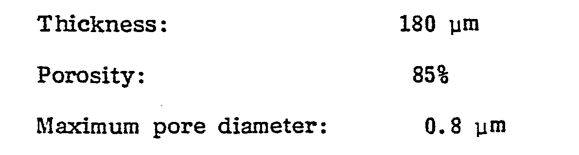
- A porous PTFE membrane containing silver-supported carbon black and having the following physical properties was prepared in the same manner as in Example 1 except that the silver-supported carbon black was prepared in accordance with Example 2 from the carbon black as used in Comparative Example 1 and used.

- Without depositing platinum on the membrane, an electrode was prepared in the same manner as in Example 1, and the electrolysis was conducted in the same manner as in Example 1, whereby the initial cell voltage was 3.32V, and the increase of the cell voltage after the continuous electrolysis for 3,000 hours was 0. 41V over the initial cell voltage.
- Carbon black powder (VULCAN XC-72R, trade name, manufactured by Cabbot Company, U.S.A.,) was heated for 30 minutes at 2,000°C in the same manner as in Example 1, whereby the powder was partially graphitized. The powder is added to an aqueous iron formate solution, and the mixture was stirred and heated to remove water. Then, the mixture was heated under vacuum at 150°C to decompose iron formate. The powder thereby obtained, contained 0.1% of iron. Then, this powder was heated to 500°C in a nitrogen stream, then exposed to oxygen gas for 30 seconds for oxidation, and cooled in a nitrogen stream and then stirred. The oxidation operation was repeated until the weight of the powder was reduced by 15%. Then, the powder was washed with a 50% nitric acid solution to remove iron from the powder, then washed with water and dried at 100°C, whereby partially graphitized carbon black having a pit on the surface of the particles was obtained.
- Then, a mixture comprising 55% by weight of PTFE powder and 45% by weight of the above-mentioned partially graphitized carbon black having pits on the surface of the particles, was prepared by a flocculation method. A liquid lubricant (solvent naphtha) was incorporated into this mixture to obtain a paste-like mixture. This mixture was compressed and extruded by a ram from a fish tail to obtain a sheet material having a thickness of 1. 2 mm. Then, the sheet material was further rolled in a direction perpendicular to the extrusion direction to obtain a thin sheet having a thickness of 0.35 mm. This sheet was monoaxially stretched by 1.6 times under the pre-heated condition at 310°C. While fixing the length of the stretched sheet in the stretching direction, the sheet was heated at 360°C for complete sintering treatment, whereby a porous PTFE membrane containing carbon black was obtained. The physical properties of this membrane were as' follows.

- The membrane was immersed in a mixed solution of 10 cc of a 10% chloroplatinic acid aqueous solution and 40 cc of isopropanol. After fixing the periphery, the membrane was dried and further treatead in a hydrogen stream at 200°C to reduce the chloroplatinic acid to platinum, whereby a porous PTFE membrane containing carbon black with 0.5 mg/cm2 of platinum deposited thereon was obtained. The membrane was heat-pressed at 300°C to a silver plated nickel expanded mesh (breadthwise pitch: 1 mm, lengthwise pitch: 2 mm, thickness: 0.1 mm) coated with a mixture of carbon black and FEP (mixing ratio of 3 : 2), whereby an electrode was obtained.
- By using this electrode as a cathode, an electrolytic cell as shown in Figure 1 was prepared wherein a membrane and an anode were provided in contact with each other, and the distance between the membrane and the cathode was maintained to be 5 mm. As the anode, a metal anode prepared by coating a solid solution of ruthenium oxide and iridium oxide on the surface of a titanium expanded metal, was used. As the membrane, a fluorine-containing cation-exchange membrane obtained by hydrolyzing a membrane-like material (thickness: 280 µm, ion-exchange capacity: 1.44 meq/g dry resin) made of a copolymer of C2F4 with CF2=CFO(CF2)3COOCH3 and having 1 mg/cm2 of a porous layer of zirconium oxide embedded on the anode side surface, was used. An aqueous solution of 5N sodium chloride was electrolyzed at a current of 4A (current density; 20A/dm2) while supplying 1ℓ/min. of air free from carbon dioxide gas, to the gas supply chamber. The electrolysis was conducted by adjusting the amount of the sodium chloride solution supplied to the anode compartment and the amount of water supplied to the cathode compartment so that the sodium chloride concentration in the anode compartment was maintained at 3.5N and the sodium hydroxide concentration in the cathode compartment was maintained at 35% by weight. The initial cell voltage was 2.15V, and the increase of the cell voltage after the continuous operation of the electrolysis for 3, 000 hours was 0. 03V. The current efficiency for the production of sodium hydroxide during this period was 93.5%.
- A porous PTFE membrane containing silver- supported carbon black and having the following physical properties, was prepared in the same manner as in Example 3 except that carbon black supporting 60% by weight of silver was used instead of the carbon black used in
-


- Further, the electrolysis was conducted for an extended period of 3,000 hours, whereby the increase of the cell voltage during this period was 0.03V over the initial cell voltage.
Claims (10)
- L. A gas diffusion electrode material which comprises a continuously nicro-porous electrically insulating material and at least partially graphitized carbon black powder uniformly incorporated in the insulating material.
- 2. The gas diffusion electrode material according to Claim 1, wherein the graphitized carbon black powder is carbon black graphitized by heat treatment at a temperature of from 1,200 to 2, 500°C for from 5 to 60 minutes.
- 3. The gas diffusion electrode material according to Claim 1, wherein the graphitized carbon black powder is graphitized carbon black subjected to etching treatment.
- 4. The gas diffusion electrode material according to Claim 3, wherein the etching treatment is conducted by oxidation treatment of graphitized carbon black.
- 5. The gas diffusion electrode material according to Claim 4, wherein the oxidation treatment is conducted by heat treatment in an oxygen atmosphere or by treatment with an oxidizing agent such as nitric acid, sulfuric acid or a permanganate.
- 6. The gas diffusion electrode material according to Claim 1, wherein the continuously micro-porous electrically insulating material is made of a polytetrafluoroethylene.
- 7. The gas diffusion electrode material according to Claim 1, wherein the continuously micro-porous electrically insulating material is composed of a numerous fine nodes of a polytetrafluoroethylene and fine fibers of a polytetrafluoroethylene extending from the nodes and three dimensionally connecting the nodes to one another, the nodes being partially in contact or connected with one another.
- 8. The gas diffusion electrode material according to Claim 1, wherein the graphitized carbon black powder has a particle size of at most 1 µm.
- 9. The gas diffusion electrode material according to Claim 1, wherein the graphitized carbon black is incorporated in an amount of from
- 7 to 90% by weight based on the total weight of the continuously micro-porous electrically insulating material and the graphitized carbon black powder.
Applications Claiming Priority (4)
| Application Number | Priority Date | Filing Date | Title |
|---|---|---|---|
| JP57134768A JPS5925179A (en) | 1982-08-03 | 1982-08-03 | Material for gas diffusion electrode |
| JP134769/82 | 1982-08-03 | ||
| JP134768/82 | 1982-08-03 | ||
| JP57134769A JPS5925180A (en) | 1982-08-03 | 1982-08-03 | Material for gas diffusion electrode |
Publications (2)
| Publication Number | Publication Date |
|---|---|
| EP0100548A2 true EP0100548A2 (en) | 1984-02-15 |
| EP0100548A3 EP0100548A3 (en) | 1985-11-27 |
Family
ID=26468779
Family Applications (1)
| Application Number | Title | Priority Date | Filing Date |
|---|---|---|---|
| EP83107573A Withdrawn EP0100548A3 (en) | 1982-08-03 | 1983-08-01 | Gas diffusion electrode material |
Country Status (2)
| Country | Link |
|---|---|
| US (1) | US4551220A (en) |
| EP (1) | EP0100548A3 (en) |
Cited By (7)
| Publication number | Priority date | Publication date | Assignee | Title |
|---|---|---|---|---|
| EP0273562A3 (en) * | 1986-11-11 | 1989-09-27 | Sharp Kabushiki Kaisha | A method for the production of a carbon electrode |
| US5702839A (en) * | 1993-11-23 | 1997-12-30 | Johnson Matthey Public Limited Company | Manufacture of electrodes |
| GB2337150A (en) * | 1998-05-07 | 1999-11-10 | Nat Power Plc | Carbon based electrodes |
| WO2001092151A1 (en) * | 2000-05-31 | 2001-12-06 | Showa Denko K.K. | Electrically conductive fine carbon composite, catalyst for solid polymer fuel cell and fuel battery |
| US6669976B2 (en) | 2000-03-24 | 2003-12-30 | Nestec S.A. | Self-foaming soluble beverage powder |
| US6780388B2 (en) | 2000-05-31 | 2004-08-24 | Showa Denko K.K. | Electrically conducting fine carbon composite powder, catalyst for polymer electrolyte fuel battery and fuel battery |
| EP1519433A1 (en) * | 2003-09-26 | 2005-03-30 | Samsung SDI Co., Ltd. | Diffusion electrode for fuel cell |
Families Citing this family (30)
| Publication number | Priority date | Publication date | Assignee | Title |
|---|---|---|---|---|
| FR2574803B1 (en) * | 1984-12-18 | 1987-01-30 | Occidental Chem Co | ELECTRICALLY CONDUCTIVE THERMOPLASTIC MATERIAL AND METHOD FOR MANUFACTURING SUCH MATERIAL |
| US5273639A (en) * | 1988-03-31 | 1993-12-28 | Agency Of Industrial Science & Technology | Probe electrode |
| US5174883A (en) * | 1988-09-02 | 1992-12-29 | The Dow Chemical Company | Ultramicroelectrode ensembles |
| US5543021A (en) * | 1994-09-01 | 1996-08-06 | Le Carbone Lorraine | Negative electrode based on pre-lithiated carbonaceous material for a rechargeable electrochemical lithium generator |
| US6159533A (en) * | 1997-09-11 | 2000-12-12 | Southwest Research Institute | Method of depositing a catalyst on a fuel cell electrode |
| US6153327A (en) * | 1995-03-03 | 2000-11-28 | Southwest Research Institute | Amorphous carbon comprising a catalyst |
| US6001500A (en) * | 1996-06-05 | 1999-12-14 | Southwest Res Inst | Cylindrical proton exchange membrane fuel cells and methods of making same |
| US6063517A (en) * | 1997-10-16 | 2000-05-16 | Southwest Research Institute | Spiral wrapped cylindrical proton exchange membrane fuel cells and methods of making same |
| US6610436B1 (en) * | 1998-09-11 | 2003-08-26 | Gore Enterprise Holdings | Catalytic coatings and fuel cell electrodes and membrane electrode assemblies made therefrom |
| WO2000032512A1 (en) | 1998-12-02 | 2000-06-08 | Massachusetts Institute Of Technology | Integrated palladium-based micromembranes for hydrogen separation and hydrogenation/dehydrogenation reactions |
| US7008718B2 (en) * | 2000-05-08 | 2006-03-07 | Honda Giken Kogyo Kabushiki Kaisha | Fuel cell assembly |
| US6818338B2 (en) * | 2000-05-08 | 2004-11-16 | Honda Giken Kogyo Kabushiki Kaisha | Fuel cell assembly |
| US6558828B1 (en) | 2000-05-26 | 2003-05-06 | Eveready Battery Company, Inc. | Zn/air cell performance in extreme humidity by controlling hydrophobic layer porosity |
| DE10027339A1 (en) * | 2000-06-02 | 2001-12-06 | Bayer Ag | Dimensionally stable gas diffusion electrode |
| DE10296225B4 (en) * | 2001-02-07 | 2013-12-05 | Asahi Kasei Kabushiki Kaisha | A method for producing an ion exchange fluorocarbon resin membrane, an ion exchange fluorocarbon resin membrane obtained according to the method, a membrane electrode assembly, and a fuel cell equipped with the membrane |
| JP2002246034A (en) * | 2001-02-21 | 2002-08-30 | Sony Corp | Gas diffusible electrode body, method for producing the same, and electrochemical device |
| US6593023B2 (en) * | 2001-04-27 | 2003-07-15 | The Gillette Company | Battery and method of making the same |
| US20030008195A1 (en) * | 2001-06-28 | 2003-01-09 | Chiem Bien Hung | Fluid diffusion layers for fuel cells |
| JP2004079406A (en) * | 2002-08-21 | 2004-03-11 | Nisshinbo Ind Inc | Method for producing gas diffusion electrode and fuel cell |
| US7157178B2 (en) * | 2003-11-24 | 2007-01-02 | General Motors Corporation | Proton exchange membrane fuel cell |
| US7608334B2 (en) | 2005-03-29 | 2009-10-27 | 3M Innovative Properties Company | Oxidatively stable microlayers of gas diffusion layers |
| JP4842294B2 (en) * | 2008-04-30 | 2011-12-21 | 日東電工株式会社 | Porous sheet, method for producing the same, and heat insulating sheet |
| CN101736360B (en) * | 2009-11-27 | 2011-06-01 | 北京化工大学 | A gas diffusion electrode and its preparation method |
| EP2954951B1 (en) | 2014-06-11 | 2023-08-02 | Heraeus Deutschland GmbH & Co. KG | Carrier catalyst and method for producing a porous graphitised carbon material coated with metal nanoparticles |
| US9831503B2 (en) | 2014-12-03 | 2017-11-28 | Coulombic, Inc. | Electrodes and electrochemical devices and methods of making electrodes and electrochemical devices |
| US10650981B2 (en) | 2015-01-30 | 2020-05-12 | Massachusetts Institute Of Technology | Fluorinated coatings for high performance electrodes |
| WO2016187143A1 (en) | 2015-05-15 | 2016-11-24 | Composite Materials Technology, Inc. | Improved high capacity rechargeable batteries |
| US9997815B2 (en) * | 2016-08-05 | 2018-06-12 | Toyota Motor Engineering & Manufacturing North America, Inc. | Non-aqueous magnesium-air battery |
| KR20190077321A (en) | 2016-09-01 | 2019-07-03 | 컴포짓 매터리얼스 테크놀로지, 아이엔씨. | Nano-scale / nano-structured Si coating on valve metal substrate for LIB anode |
| US12221685B2 (en) | 2022-03-16 | 2025-02-11 | Coulombic, Inc. | Diamond-like carbon materials and methods of making diamond-like carbon materials |
Family Cites Families (10)
| Publication number | Priority date | Publication date | Assignee | Title |
|---|---|---|---|---|
| US3196050A (en) * | 1962-05-29 | 1965-07-20 | Exxon Research Engineering Co | Method of preparing a catalyst impregnated carbon electrode |
| FR1581381A (en) * | 1967-10-27 | 1969-09-12 | ||
| US4046654A (en) * | 1976-04-06 | 1977-09-06 | Marc Cole | Process for desalination with chlor-alkali production in a mercury diaphragm cell |
| US4054687A (en) * | 1976-06-01 | 1977-10-18 | United Technologies Corporation | Method for making a fuel cell electrode |
| US4120774A (en) * | 1977-01-24 | 1978-10-17 | Energy Development Associates | Reduction of electrode overvoltage |
| US4278525A (en) * | 1978-04-24 | 1981-07-14 | Diamond Shamrock Corporation | Oxygen cathode for alkali-halide electrolysis cell |
| CA1175387A (en) * | 1979-01-17 | 1984-10-02 | Rene Muller | Electrolysis electrode of graphite, polytetrafluoroethylene, and platinum metal oxides |
| IT1122385B (en) * | 1979-08-01 | 1986-04-23 | Oronzio De Nora Impianti | ELECTRODE FOR SOLID ELECTROLYTE ELECTROCHEMICAL CELLS |
| US4354958A (en) * | 1980-10-31 | 1982-10-19 | Diamond Shamrock Corporation | Fibrillated matrix active layer for an electrode |
| US4364805A (en) * | 1981-05-08 | 1982-12-21 | Diamond Shamrock Corporation | Gas electrode operation |
-
1983
- 1983-07-28 US US06/517,957 patent/US4551220A/en not_active Expired - Fee Related
- 1983-08-01 EP EP83107573A patent/EP0100548A3/en not_active Withdrawn
Cited By (10)
| Publication number | Priority date | Publication date | Assignee | Title |
|---|---|---|---|---|
| EP0273562A3 (en) * | 1986-11-11 | 1989-09-27 | Sharp Kabushiki Kaisha | A method for the production of a carbon electrode |
| US5702839A (en) * | 1993-11-23 | 1997-12-30 | Johnson Matthey Public Limited Company | Manufacture of electrodes |
| US5871860A (en) * | 1993-11-23 | 1999-02-16 | Johnson Matthey Public Limited Company | Manufacture of electrodes |
| GB2337150A (en) * | 1998-05-07 | 1999-11-10 | Nat Power Plc | Carbon based electrodes |
| GB2337150B (en) * | 1998-05-07 | 2000-09-27 | Nat Power Plc | Carbon based electrodes |
| US6511767B1 (en) | 1998-05-07 | 2003-01-28 | Regenesys Technologies Limited | Carbon based electrodes |
| US6669976B2 (en) | 2000-03-24 | 2003-12-30 | Nestec S.A. | Self-foaming soluble beverage powder |
| WO2001092151A1 (en) * | 2000-05-31 | 2001-12-06 | Showa Denko K.K. | Electrically conductive fine carbon composite, catalyst for solid polymer fuel cell and fuel battery |
| US6780388B2 (en) | 2000-05-31 | 2004-08-24 | Showa Denko K.K. | Electrically conducting fine carbon composite powder, catalyst for polymer electrolyte fuel battery and fuel battery |
| EP1519433A1 (en) * | 2003-09-26 | 2005-03-30 | Samsung SDI Co., Ltd. | Diffusion electrode for fuel cell |
Also Published As
| Publication number | Publication date |
|---|---|
| US4551220A (en) | 1985-11-05 |
| EP0100548A3 (en) | 1985-11-27 |
Similar Documents
| Publication | Publication Date | Title |
|---|---|---|
| US4551220A (en) | Gas diffusion electrode material | |
| US4389297A (en) | Permionic membrane electrolytic cell | |
| US4461682A (en) | Ion exchange membrane cell and electrolytic process using thereof | |
| US4655887A (en) | Process for electrolyzing aqueous solution of alkali metal chloride | |
| US4655886A (en) | Ion exchange membrane cell and electrolysis with use thereof | |
| US4299675A (en) | Process for electrolyzing an alkali metal halide | |
| US4465570A (en) | Process for producing hydrogen | |
| EP0166166B1 (en) | Process for producing potassium hydroxide | |
| CA1171026A (en) | Method of bonding electrode to cation exchange membrane | |
| US4661218A (en) | Ion exchange membrane cell and electrolysis with use thereof | |
| CA1171133A (en) | Ion exchange membrane electrolytic cell | |
| JPS621652B2 (en) | ||
| EP0066102B1 (en) | Ion exchange membrane cell and electrolysis with use thereof | |
| JPS5928581A (en) | Material for gas diffusion electrode | |
| JPS61239566A (en) | Improved gas diffusion electrode | |
| JPS59133386A (en) | Manufacture of gas diffusing electrode | |
| JPS61130497A (en) | Gas diffusing electrode | |
| JPS5925180A (en) | Material for gas diffusion electrode | |
| US4469808A (en) | Permionic membrane electrolytic cell | |
| JPS5943887A (en) | Manufacture of electrode material for gas diffusion | |
| JPS59166541A (en) | Production of porous membrane of chemical resistance | |
| JPH0219848B2 (en) | ||
| JPS5943889A (en) | Material for gas diffusion electrode | |
| JPS5940231B2 (en) | Method for producing alkali hydroxide | |
| EP0066101B1 (en) | Ion exchange membrane cell and electrolysis with use thereof |
Legal Events
| Date | Code | Title | Description |
|---|---|---|---|
| PUAI | Public reference made under article 153(3) epc to a published international application that has entered the european phase |
Free format text: ORIGINAL CODE: 0009012 |
|
| AK | Designated contracting states |
Designated state(s): DE FR GB IT |
|
| PUAL | Search report despatched |
Free format text: ORIGINAL CODE: 0009013 |
|
| AK | Designated contracting states |
Designated state(s): DE FR GB IT |
|
| 17P | Request for examination filed |
Effective date: 19860319 |
|
| 17Q | First examination report despatched |
Effective date: 19870622 |
|
| STAA | Information on the status of an ep patent application or granted ep patent |
Free format text: STATUS: THE APPLICATION IS DEEMED TO BE WITHDRAWN |
|
| 18D | Application deemed to be withdrawn |
Effective date: 19871103 |
|
| RIN1 | Information on inventor provided before grant (corrected) |
Inventor name: MORIMOTO, TAKESHI Inventor name: ODA, YOSHIO |