EP0100495A1 - Shirred sausage casing and method for its production - Google Patents
Shirred sausage casing and method for its production Download PDFInfo
- Publication number
- EP0100495A1 EP0100495A1 EP83107196A EP83107196A EP0100495A1 EP 0100495 A1 EP0100495 A1 EP 0100495A1 EP 83107196 A EP83107196 A EP 83107196A EP 83107196 A EP83107196 A EP 83107196A EP 0100495 A1 EP0100495 A1 EP 0100495A1
- Authority
- EP
- European Patent Office
- Prior art keywords
- casing
- shirring
- speed
- thickening
- twisted
- Prior art date
- Legal status (The legal status is an assumption and is not a legal conclusion. Google has not performed a legal analysis and makes no representation as to the accuracy of the status listed.)
- Withdrawn
Links
Images


Classifications
-
- A—HUMAN NECESSITIES
- A22—BUTCHERING; MEAT TREATMENT; PROCESSING POULTRY OR FISH
- A22C—PROCESSING MEAT, POULTRY, OR FISH
- A22C13/00—Sausage casings
- A22C13/02—Shirring of sausage casings
-
- Y—GENERAL TAGGING OF NEW TECHNOLOGICAL DEVELOPMENTS; GENERAL TAGGING OF CROSS-SECTIONAL TECHNOLOGIES SPANNING OVER SEVERAL SECTIONS OF THE IPC; TECHNICAL SUBJECTS COVERED BY FORMER USPC CROSS-REFERENCE ART COLLECTIONS [XRACs] AND DIGESTS
- Y10—TECHNICAL SUBJECTS COVERED BY FORMER USPC
- Y10T—TECHNICAL SUBJECTS COVERED BY FORMER US CLASSIFICATION
- Y10T428/00—Stock material or miscellaneous articles
- Y10T428/13—Hollow or container type article [e.g., tube, vase, etc.]
- Y10T428/1324—Flexible food casing [e.g., sausage type, etc.]
Definitions
- the invention relates to a gathered sausage casing of the type mentioned in the preamble of claim 1 and to a method for its production.
- the gathered sausage casing is also called a caterpillar.
- a shirred sausage casing of this type is known from EP-A-0 037 543.
- the teaching is given to use the device known from US-A-4,185,358 for gathering sausage casings which have a thickening in the form of an adhesive seam in such a way that the casing can twist itself during gathering with this special gathering device .
- this should be done, for example, by using a shirring mandrel which is smaller than the usual one.
- the seam zone is to be arranged spirally around the longitudinal axis of the shirred tubular envelope.
- the number of spiral turns in the seam zone per 10 m of sleeve length is far less than 10 and is therefore unsatisfactory for a high gathering ratio.
- a reproducible slope of the coiled seam zone cannot be achieved in this way, moreover, the hollow channel of the caterpillar does not show a perfect circular cross section, since the relatively thick seam zone is at least partially displaced into the hollow channel during gathering.
- EP-A-0 054 162 a To twist the sausage casing with an adhesive seam during the gathering process using a gathering device according to US-A-2,819,488, US-A-3,619,854, US-A-3,594,857 or US-A-3,766,603.
- the number of turns per 10 m hose length should then be between 0.5 and 10.
- a higher number of turns per 10 m hose length cannot be achieved by spiraling the hose during gathering.
- EP-A-0 054 162 does not give any indication of how the turns of the adhesive seam should run over the main folds of the bead.
- This publication cannot give any suggestion to increase the kink resistance of the gathered sheath by a special arrangement of the adhesive seam, in particular because according to this state of the art only the number of turns of the adhesive seam should be of importance.
- the object of the present invention is to provide a gathered sausage casing of the type described there, which has a significantly higher kink resistance and nevertheless a uniform, circular cross section, straight inner Has cavity with a relatively smooth inner wall, which allows a problem-free application of the gathered sausage casing on the filling tube of a filling device, even with filling tubes with a relatively large diameter, which allow a quick and therefore economical filling of sausage mass into the gathered sausage casing.
- Another object of the invention is methods to specify for the manufacture of such a gathered sausage casing.
- This shirred sausage casing has the advantage that, despite its thickening, in particular in the form of a relatively thick adhesive seam, it exhibits a significantly higher compression and at the same time has a substantially uniform outer circumference and a uniform circular inner circumference.
- the hollow channel of the caterpillar is straight and shows an essentially smooth inner wall, despite the thickening of the casing in the area of the adhesive seam. The methods are particularly simple to carry out without any changes in the apparatus being required in the gathering device.
- the relatively thick-walled seam zone which consists of at least two layers of material, can be accommodated in the caterpillar wall in such a way that both the outer surface of the caterpillar and its inner surface are smooth and uniform, so that the shirred casing can be easily applied to filling pipes with a relatively large diameter can be pushed on and runs evenly from the filling tube while unloading during the filling process.
- Tube covers with a thickening in the form of a seam or several longitudinally axially extending seams and their production by gluing the edge regions of the longitudinally axially extending edge zones are known per se, for which reference is made, for example, to EP-A-0 037 543 and EP-A-0 054 162 cited at the beginning.
- the adhesive seam is formed by the overlap and adhesive bonding of two longitudinally axially extending edge zones of a film web bent into a tube. It can also be formed by letting the longitudinal axial edges of a web abut one another during tube forming without overlapping one another, and by connecting the two edge zones to one another with a film strip.
- the width of the adhesive seam is not to be understood as the width of the adhesive layer, but rather the width of the overlapping area of the edge zones with one another or with the film strip.
- the thickness of the tube is consequently at least twice as thick as the thickness of the sleeve material or the tube thickness is composed of the thickness of the sleeve material and the thickness of the film strip.
- the width of the adhesive seam is usually up to 10% of the circumference of the tube and should be at least 1 mm.
- Suitable flexible base material for the tubular casing is preferably cellulose, i.e. Cellular glass, regenerated cellulose or cellulose hydrate, which is optionally reinforced with a fiber insert, as is customary for packaging food, in particular as a sausage casing material.
- the shirred tubular casing can have conventional coatings on its inner and / or outer surface, e.g. have on the inside a means to improve the peelability of the tubular casing from the contents.
- the ruched sausage casing shows the fold structure known from US-A-3,907,003 in the form of an outwardly pointing helical main fold or primary fold and secondary folds arranged between the turns of this main fold and the interior of the gathered sausage casing.
- the spiral primary fold lies on the outer circumference and forms it itself.
- the spiral primary fold appears in the unfolded state in parallel rectilinear fold lines which form an angle of less than 90 * and greater than 60 ° to the longitudinal axis of the film strip obtained .
- the secondary fold structure is between the inside and outside diameter of the bead.
- the helical main fold is on the outside of the caterpillar and the secondary folds in the double layer made of casing material.
- a double layer of the casing material is thus located between two superimposed winding sections of the helical main fold.
- the secondary folds are particularly regular.
- the easily recognizable secondary fold lines show the shape of a completely continuous, uniform zigzag line, the tips of the zigzag line being at a substantially constant distance from the helical line of the main fold.
- the individual sections of this zigzag line form screw line sections with a winding direction opposite to the main fold.
- the gathered sausage casing has practically no other secondary folds.
- the strip-shaped adhesive seam extends spirally around the longitudinal axis of the gathered sausage casing.
- the adhesive seam in the form of a strip extends helically around the tubular casing, whereby the number of Wiridungen per unit length of unshirred tubular casing is substantially less auptfalte than the number of turns of the H.
- the adhesive seam extending transversely over the turns of the main fold and offset live seam width between two adjacent windings just by the amount of the width of the adhesive seam with a maximum deviation of ⁇ 10%, preferably ⁇ 5% of the K.
- a particularly high and uniform packing density of the tube material in the bead is achieved if the adhesive seam between two adjacent turns of the main fold is exactly shifted by its width.
- Particularly kink-resistant tracks are obtained according to the invention when the inclination of the double layer of the casing material in the gathered tubular casing to the longitudinal axis of the casing is as small as possible, ie when the angle between double layer and longitudinal track axis is less than 35 ', preferably 20 to 30'.
- Such a low angle of inclination is produced, for example, with the rotating, sleeve-shaped gathering element of US Pat. No. 4,185,358, in which the projection which is helically wound in the cylindrical interior of the gathering element is modified accordingly.
- this protrusion ends in the form of a chamfer on the caterpillar side.
- the chamfer angle is equal to the desired angle between the double layer and the longitudinal axis of the caterpillar.
- the casing is twisted before and / or during shirring. This is preferably done by twisting the casing before gathering and winding it in a twisted state on a roll, from which the twisted casing is then fed to the gathering device. It is particularly advantageous if the casing is twisted as soon as it is manufactured and rolled up while laying flat, immediately after its seam has been formed. In the latter case, the adhesive seam formed by the adhesive bonding of the edge zones of the endless web is twisted immediately after the tubular sheath has been formed, the twisted sheath is laid flat and wound up.
- a suitable device consists, for example, of a first pair of pull rollers, which is the glued one Disconnect the hose from the gluing station, and a second pair of pulling rollers, which rotates about the longitudinal axis of the sleeve and thereby twists the sleeve in the outlet from this second pair of pulling rollers.
- the hose is held in the inflated state with a support gas between the two pairs of pull rollers.
- the casing In the gap formed by the second pair of pull rollers, the casing is laid flat at the same time.
- elements can be attached in front of the second pair of pulling rollers, which steadily flatten the casing and gradually flatten it out.
- Suitable elements are, for example, baffles, roller conveyors, conveyor belts or guide rolls which converge to one another, as are customary, for example, in the production of extruded plastic hoses.
- All parts of the device for twisting, laying flat and winding up rotate at the same speed around the longitudinal axis of the casing. These parts are therefore expediently housed on a common rotating frame and can also be part of the tube molding system.
- the extent of the twisting of the hose and the adhesive seam is determined by the speed of rotation of these device parts or the frame and by the hose speed determined.
- the casing receives 10 turns per 10 m casing length and at a speed of the casing of 200 m / min and at a speed of 200 revolutions / min, the number of turns per 10 m sleeve length is also 10.
- a shirring ratio of, for example, 100: 1 (50: 1), with 10 turns / 10 m sleeve length the helix spacing is 1 cm (2 cm) the caterpillar.
- a dense caterpillar is achieved with this process if the number of turns per 10 m casing length is greater than 10, ie if the helix distance in the caterpillar is less than 1 cm (shirring ratio 100: 1) or less than 2 cm (shirring ratio 50: 1) is.
- This optimal number of turns per 10 m of sleeve length is achieved by the mutual adaptation of the sleeve speed and speed, the preferred range for the sleeve speed being 5 to 200 m / min and for the speed 5 to 200 rpm.
- the mutual adaptation of the casing speed and the rotational speed is determined by the quotient of the rotational speed (revolutions / min) and the casing speed (m / min), which is preferably greater than 1 (revolutions / m) and usually does not exceed 4 (revolutions / m). With these values, dense caterpillars can be produced from casings with an adhesive seam.
- any other incline of the seam or any other number of turns of the casing per unit length can be achieved.
- the shirring mandrel is a hollow tube that supports the tube and gives the tube bead created during shirring a certain inner diameter.
- the tube is slightly inflated through the tube during gathering in order to give it the plump shape required for the attack of the gathering forces.
- the sausage casing is rotated about the shirring pin, whereby the gusset folds are rotated into a helical pattern, possibly in addition to the previous twisting.
- the force used for gathering is applied by an element rotating about the longitudinal axis of the tubular casing, which element is constantly in force engagement with the tubular casing during the gathering process and exerts sufficient compressive force on the tubular casing to form the rigid caterpillar (US Pat. No. 4,185,358).
- the tubular casing to be gathered is provided with a lubricant and / or moistening agent before or during the gathering process.
- the device for performing the gathering process consists of a Rafforgan and an abutment, wherein the Rafforgan consists of a tubular part enclosing and rotatable about this ring part, to which the element used for gathering and engaging with the tubular casing is fastened.
- the ring part is a basically known internally helical toothed rotating sleeve which exerts an axially compressing force on the hose material (US Pat. No. 4,185,358).
- a helically wound projection which protrudes from the inside of the sleeve as a screw turn.
- the rotational speed U RE (revolution / min) of the rotating sleeve-shaped gathering element must be chosen in the case of an ideal displacement of the strip-shaped thickening, in particular adhesive seam, between successive main folds in such a way that its ratio to the rotational speed U s (revolution / min), with which the hose is twisted or twisted during its manufacture and / or during gathering, the following relationship is fulfilled:
- the two rotational speeds are thus in the Ideally in a ratio as it results from the ratio of the outer circumference of the caterpillar and the width of the thickening or the seam zone.
- Viscose is pressed through a gap into an acidic coagulation bath.
- the cellulose hydrate gel sheet obtained after the regeneration is passed through a plasticizer bath consisting of a 9% by weight aqueous glycerol solution.
- the web of regenerated cellulose obtained has a weight per unit area of 41 g / m 2 , a water content of approximately 8% by weight and a glycerol content of approximately 15% by weight.
- the water content may be adjusted by rewetting.
- the web material also shows a tensile strength of 48 to 53 N / mm 2 in the transverse direction.
- the cellulose web is cut into 60 mm wide tapes.
- Each band-shaped blank is made with a device, as shown in FIG. 8 of EP-A-0 037 543, along one of its two edges with a 12% by weight aqueous solution (pH 7.5, adjusted with concentrated ammonia solution) of a water-soluble cationic resin coated in strips in the longitudinal direction of the tape and, as also shown there, formed into a tube.
- the cationic resin is a reaction product of ethylene diamine, adipic acid, diethylene triamine and epichlorohydrin and is commercially available as a 12 and 20% by weight aqueous solution under the name® Resamin HW 601 (manufacturer Cassella).
- the solution is transferred by means of a rotating, about 2 mm wide applicator roll from a storage trough for the current film strip, where it holds at a wet film thickness 10 to 12 / um, a width of 2 to 3 mm a.
- the respective regions close to the edges form an overlapping adhesive seam running in the longitudinal direction (cf. FIG.
- the tubular casings thus produced and wound in a twisted manner are unwound from the roll at a speed of 40 m / min after a storage period of 3 days and with that known from US Pat. No. 4,185,358 Device gathered in a gathering ratio of 1:75.
- the shirring mandrel is fixed and has a diameter of 11.5 mm.
- the inside thread of the sleeve-shaped gathering element shows a chamfer of 30 "on the caterpillar side in relation to the axis of rotation.
- the caterpillars obtained have an outer diameter of 18 mm and an inner hollow channel with a diameter of 11.5 mm.
- the spiral distance of the seam zone on the caterpillars is 0.45 cm.
- the gathering density is the quotient of hose length / caterpillar length and is at the usual values, i.e. between 20 and 120.
- the breaking strength of the caterpillar samples is checked by measuring the breaking moment B.
- the breaking moment B is then (L / 2) p.
- the caterpillar C has the highest breaking strength and a very smooth and uniform appearance.
- This sample has such a displacement of the seam zone that there is exactly a shift of the seam zone by the width of the seam zone (3.5 mm) on the outer circumference of the bead from main fold to main fold, while the other samples do not have this ideal condition.
- the overlap is shifted in such a way that there is a greater displacement of the seam zone in the circumferential direction from main fold to main fold.
- Samples D to H increasingly overlap the seam zones from main fold to main fold.
- caterpillars according to C are best suited for use on high-performance filling machines.
- the bead samples A, B and D do not show optimal properties. Their breaking strength is still sufficient for simple filling machines.
- the hollow channel of bead samples A to D is straight and has a smooth inner wall.
- the caterpillars can be pushed onto the filling tube of a tamping device without any problems and are filled evenly when the sausage mixture is pressed in.
- the shirring machine is shirred with the same settings as for sample C of example 1, but using sleeve-shaped shirring elements with a helical projection on the inside, the chamfering of which at the end of the shirring element facing the caterpillar in the area is varied from 40 ° to 20 °.
- the optimum breaking strength is at angles of inclination of less than 35 °, in particular between 30 and 20 °.
- a shirring machine US-A-4,185,358
- the caterpillar D is the only one which has the ideal displacement of the overlap and is the best caterpillar in this test series with regard to uniform appearance and strength.
- Fig. 1 the shirred tubular casing 1 shows a coiled seam zone 2 with a uniform slope.
- the part of the seam zone 2 shown in dashed lines is located in the double layer 25 between two turns of the main fold 24.
- the hollow channel of the caterpillar is designated by 28.
- the caterpillar 1, shown in detail and enlarged in FIGS. 1 a and 1 b, is shown in a somewhat wound state.
- the web 4 of cellulose is unwound from a roll 3, passed through a form template 5 and formed with the support tube 7 and the sleeve 8 into a tube 6, the two edges approaching the form template 5.
- the support tube 7 and the sleeve 8 serve to support the hose formation, the hose being supported from the inside and outside.
- the application device 9 uses a nozzle 11 to produce a strip-shaped application of the adhesive solution 10 between the overlapping edge zones of the web 4. After passing through the drawing rollers 12, 12 'and deflection rollers 13, the tube is inflated between two pairs of squeezing rollers 14, 14' and 15, 15 ' and wound up with the roll 16.
- the pinch roller pair 15, 15 'and the roller 16 are located on a common frame 17, which is rotated with the drive motor 18, as a result of which the hose seam 2 is wound on the roller 16 in a twisted form.
- the reference numerals have the same loading interpretation as in the previous figures.
- the twisted coiled tube 6 is unwound from the roll 16 and held after passing through the nip rolls 19 19 'in the inflated state, wherein by the R affdorn is blown air 26 in a known, 20.
- the inflated hose 6 moves through two further driven rollers 21, 21 'in the direction of the sleeve-shaped gathering element 22, where the actual gathering process takes place. With 23 an abutment is designated against which the hose is compressed to the caterpillar 1.
- Fig. 5 the fold pattern and the course of the seam zone 2 is shown, as it results when the caterpillar is unraveled, the tubular casing obtained is cut open in the longitudinal axial direction and laid flat.
- the zigzag lines of the secondary fold 27 are located between the fold lines of the spiral main fold 24.
- a piece of the caterpillar 1 is shown, at the one end of which the tubular casing 6 is shown as a piece pulled off.
- FIG. 7 shows the end 29 of the spiral-shaped projection of the sleeve-shaped gathering element 22 facing the abutment 23 (FIG. 4) and the gathered tubular casing 1.
- the projection is provided with the reference number 21 in FIG. 5 of US Pat. No. 4,185,358.
- the present FIG. 7 serves to explain the angle a between the surface of the gathering fold, which extends from the winding of the main fold 24 to the inside surface of the caterpillar Extends hollow channel 28 and the longitudinal axis of the caterpillar or the angle a of the chamfer 30.
- the angle a can be determined from the fold height h, which results from half the difference between the outer and inner diameter D a or D i of the caterpillar, and the length L f of the pleats. The relationship applies
- the aforementioned surface of the gathering pleat forms a truncated cone surface to the longitudinal axis of rotation and shows the inclination of the double layer 25, which is located between two adjacent turns of the main pleat 24.
- the gathered sausage casing of the invention is - despite the thickening, e.g. in the form of an adhesive seam - evenly formed, has a straight inner hollow channel with a uniform circular large cross-section, shows high rigidity and breaking strength. The folds are held tight and tight.
- the sausage casing allows safe handling during transport and can be easily used on fast-working filling machines.
- the large cross-section of the hollow channel allows the use of filling pipes with large diameters, which means that the sausage casing can be stuffed with sausage mass more quickly.
Landscapes
- Life Sciences & Earth Sciences (AREA)
- Engineering & Computer Science (AREA)
- Wood Science & Technology (AREA)
- Zoology (AREA)
- Food Science & Technology (AREA)
- Processing Of Meat And Fish (AREA)
- Containers And Plastic Fillers For Packaging (AREA)
- Meat, Egg Or Seafood Products (AREA)
Abstract
Bei der gerafften Wurstülle (1), bestehend aus einer schlauchförmigen Hülle mit einer längsaxial sich erstreckenden Verdickung (2), z.B. Klebenaht, ist diese Verdickung (2) spiralförmig angeordnet und erstreckt sich quer zu den die Außenseite der gerafften Wursthülle (1) bildenden spiralförmigen Windungen (24) der Hauptfalte. Zwischen zwei benachbarten Windungen (24) der Hauptfalte ist die Verdickung (2) um ihre Breite versetzt.In the gathered sausage casing (1), consisting of a tubular casing with a longitudinally extending thickening (2), e.g. Adhesive seam, this thickening (2) is arranged spirally and extends transversely to the spiral turns (24) of the main fold forming the outside of the gathered sausage casing (1). The thickening (2) is offset by its width between two adjacent turns (24) of the main fold.
Description
Geraffte Wursthülle und Verfahren zu ihrer Herstellung.Ruched sausage casing and process for its manufacture.
Die Erfindung bezieht sich auf eine geraffte Wursthülle von der im Oberbegriff des Anspruchs 1 genannten Art und auf ein Verfahren zu ihrer Herstellung. Die geraffte Wursthülle wird auch als Raupe bezeichnet.The invention relates to a gathered sausage casing of the type mentioned in the preamble of
Eine geraffte Wursthülle dieser Art ist aus der EP-A-O 037 543 bekannt. Dort wird die Lehre gegeben, die aus der US-A-4,185,358 bekannte Vorrichtung zum Raffen von Wursthüllen, die eine Verdickung in Form einer Klebenaht aufweisen, in der Weise zu verwenden, daß sich die Hülle während des Raffens mit dieser speziellen Raffvorrichtung selbständig verdrehen kann. Das soll nach dieser Druckschrift beispielsweise dadurch geschehen, daß man einen Raffdorn einsetzt, der gegenüber dem üblichen verkleinert ist. Auf diese Weise soll bei einer Hülle mit einer Klebenaht die Nahtzone spiralig um die Längsachse der gerafften Schlauchhülle angeordnet werden. Die Anzahl der spiralförmigen Windungen der Nahtzone pro 10 m Hüllenlänge ist jedoch weit geringer als 10 und damit für ein hohes Raffverhältnis nicht befriedigend. Außerdem kann auf diese Weise keine reproduzierbare Steigung der gewendelten Nahtzone erreicht werden, zudem zeigt der Hohlkanal der Raupe keinen einwandfreien kreisförmigen Querschnitt, da die relativ dicke Nahtzone beim Raffen zumindest teilweise in den Hohlkanal hineinverlagert wird.A shirred sausage casing of this type is known from EP-A-0 037 543. There the teaching is given to use the device known from US-A-4,185,358 for gathering sausage casings which have a thickening in the form of an adhesive seam in such a way that the casing can twist itself during gathering with this special gathering device . According to this document, this should be done, for example, by using a shirring mandrel which is smaller than the usual one. In this way, in the case of an envelope with an adhesive seam, the seam zone is to be arranged spirally around the longitudinal axis of the shirred tubular envelope. However, the number of spiral turns in the seam zone per 10 m of sleeve length is far less than 10 and is therefore unsatisfactory for a high gathering ratio. In addition, a reproducible slope of the coiled seam zone cannot be achieved in this way, moreover, the hollow channel of the caterpillar does not show a perfect circular cross section, since the relatively thick seam zone is at least partially displaced into the hollow channel during gathering.
Es wurde ferner in der EP-A-0 054 162 beschrieben, eine Wursthülle mit einer Klebenaht während des Raffvorgangs spiralförmig zu verdrehen, indem man eine Raffvorrichtung entsprechend US-A-2,819,488, US-A-3,619,854, US-A-3,594,857 oder US-A-3,766,603 verwendet. Die Anzahl der Windungen pro 10 m Schlauchlänge soll dann zwischen 0,5 und 10 betragen. Eine höhere Anzahl von Windungen pro 10 m Schlauchlänge läßt sich durch eine spiralige Verdrehung des Schlauches während des Raffens nicht erzielen. Ferner ist der EP-A-0 054 162 kein Hinweis zu entnehmen, in welcher Weise die Windungen der Klebenaht über die Hauptfalten der Raupe verlaufen sollen. Eine Anregung, die Knickfestigkeit der gerafften Hülle durch eine spezielle Anordnung der Klebenaht zu erhöhen, kann diese Druckschrift nicht geben, insbesondere weil nach diesem Stand der Technik nur die Anzahl der Windungen der Klebenaht von Bedeutung sein soll.It has also been described in EP-A-0 054 162, a To twist the sausage casing with an adhesive seam during the gathering process using a gathering device according to US-A-2,819,488, US-A-3,619,854, US-A-3,594,857 or US-A-3,766,603. The number of turns per 10 m hose length should then be between 0.5 and 10. A higher number of turns per 10 m hose length cannot be achieved by spiraling the hose during gathering. Furthermore, EP-A-0 054 162 does not give any indication of how the turns of the adhesive seam should run over the main folds of the bead. This publication cannot give any suggestion to increase the kink resistance of the gathered sheath by a special arrangement of the adhesive seam, in particular because according to this state of the art only the number of turns of the adhesive seam should be of importance.
Ausgehend von dem aus der EP-A-0 037 543 bekannten Stand der Technik besteht die Aufgabe der vorliegenden Erfindung darin, eine geraffte Wursthülle von der dort beschriebenen Art aufzuzeigen, die eine wesentlich höhere Knickfestigkeit und trotzdem einen gleichmäßigen, im Querschnitt kreisförmigen, geraden inneren Hohlraum mit relativ glatter Innenwandung aufweist, der ein problemloses Aufbringen der gerafften Wursthülle auf das Füllrohr einer Füllvorrichtung gestattet, und zwar auch bei Füllrohren mit relativ großem Durchmesser, welche ein schnelles und damit wirtschaftliches Abfüllen von Wurstmasse in die geraffte Wursthülle ermöglichen. Eine weitere Aufgabe der Erfindung besteht darin, Verfahren zur Herstellung einer solchen gerafften Wursthülle anzugeben.Based on the prior art known from EP-A-0 037 543, the object of the present invention is to provide a gathered sausage casing of the type described there, which has a significantly higher kink resistance and nevertheless a uniform, circular cross section, straight inner Has cavity with a relatively smooth inner wall, which allows a problem-free application of the gathered sausage casing on the filling tube of a filling device, even with filling tubes with a relatively large diameter, which allow a quick and therefore economical filling of sausage mass into the gathered sausage casing. Another object of the invention is methods to specify for the manufacture of such a gathered sausage casing.
Diese Aufgabe wird gelöst mit der im Anspruch 1 genannten gerafften Wursthülle sowie durch Verfahren mit den in Anspruch 9 und 16 beschriebenen Merkmalen. Die Unteransprüche geben weitere Ausführungsformen der Wursthülle bzw. des Verfahrens an.This object is achieved with the gathered sausage casing mentioned in
Diese geraffte Wursthülle zeigt den Vorteil, daß sie trotz ihrer Verdickung, insbesondere in Form einer relativ dicken Klebenaht, eine wesentlich höhere Verdichtung zeigt und gleichzeitig einen im wesentlichen gleichmäßigen äußeren Umfang sowie gleichmäßigen kreisförmigen Innenumfang aufweist. Der Hohlkanal der Raupe ist geradlinig und zeigt eine im wesentlichen glatte Innenwand, trotz der Verdickung der Hülle im Bereich der Klebenaht. Die Verfahren sind besonders einfach durchzuführen, ohne daß in der Raffvorrichtung irgendwelche apparative Veränderungen erforderlich sind. überraschenderweise läßt sich mit diesen Verfahren die relativ dickwandige Nahtzone, die aus mindestens zwei Materiallagen besteht, derart in der Raupenwandung unterbringen, daß sowohl die Raupenaußenfläche als auch ihre innere Oberfläche glatt und gleichmäßig sind, so daß die geraffte Hülle problemlos auf Füllrohre mit relativ großem Durchmesser aufgeschoben werden kann und beim Füllvorgang gleichmäßig unter Entraffen vom Füllrohr abläuft.This shirred sausage casing has the advantage that, despite its thickening, in particular in the form of a relatively thick adhesive seam, it exhibits a significantly higher compression and at the same time has a substantially uniform outer circumference and a uniform circular inner circumference. The hollow channel of the caterpillar is straight and shows an essentially smooth inner wall, despite the thickening of the casing in the area of the adhesive seam. The methods are particularly simple to carry out without any changes in the apparatus being required in the gathering device. Surprisingly, with this method, the relatively thick-walled seam zone, which consists of at least two layers of material, can be accommodated in the caterpillar wall in such a way that both the outer surface of the caterpillar and its inner surface are smooth and uniform, so that the shirred casing can be easily applied to filling pipes with a relatively large diameter can be pushed on and runs evenly from the filling tube while unloading during the filling process.
Schlauchhüllen mit einer Verdickung in Form einer Naht oder mehreren längsaxial sich erstreckenden Nähten und ihre Herstellung durch Verklebung der Randbereiche der längsaxial sich erstreckenden Randzonen sind an sich bekannt, wozu beispielsweise auf die eingangs zitierte EP-A-0 037 543 und EP-A-0 054 162 verwiesen wird.Tube covers with a thickening in the form of a seam or several longitudinally axially extending seams and their production by gluing the edge regions of the longitudinally axially extending edge zones are known per se, for which reference is made, for example, to EP-A-0 037 543 and EP-A-0 054 162 cited at the beginning.
Die Klebenaht wird gebildet durch die Überlappung und Verklebung zweier längsaxial sich erstreckender Randzonen einer zu einem Schlauch gebogenen Folienbahn. Sie kann auch gebildet werden, indem man die längsaxialen Kanten einer Bahn bei der Schlauchformung aneinanderstoßen läßt, ohne daß sie sich gegenseitig überlappen, und beide Randzonen mit einem Folienstreifen miteinander verbindet. Unter Breite der Klebenaht ist nicht die Breite der Klebstoffschicht, sondern die Breite des Überlappungsbereichs der Randzonen miteinander bzw, mit dem Folienstreifen zu verstehen. Im Bereich der Klebenaht ist die Dicke des Schlauchs folglich mindestens doppelt so dick wie die Dicke des Hüllenmaterials bzw. setzt sich die Schlauchdicke zusammen aus Dicke des, Hüllenmaterials und Dicke des Folienstreifens. Die Breite des Klebenaht beträgt gewöhnlich bis zu 10 % des Schlauchumfangs und sollte mindestens 1 mm betragen.The adhesive seam is formed by the overlap and adhesive bonding of two longitudinally axially extending edge zones of a film web bent into a tube. It can also be formed by letting the longitudinal axial edges of a web abut one another during tube forming without overlapping one another, and by connecting the two edge zones to one another with a film strip. The width of the adhesive seam is not to be understood as the width of the adhesive layer, but rather the width of the overlapping area of the edge zones with one another or with the film strip. In the area of the adhesive seam, the thickness of the tube is consequently at least twice as thick as the thickness of the sleeve material or the tube thickness is composed of the thickness of the sleeve material and the thickness of the film strip. The width of the adhesive seam is usually up to 10% of the circumference of the tube and should be at least 1 mm.
Geeignetes flexibles Basismaterial für die Schlauchhülle ist vorzugsweise Cellulose, d.h. Zellglas, regenerierte Cellulose oder Cellulosehydrat, die gegebenenfalls mit einer Fasereinlage verstärkt ist, wie sie zur Verpackung von Lebensmitteln, insbesondere als Wursthüllenmaterial, üblich ist.Suitable flexible base material for the tubular casing is preferably cellulose, i.e. Cellular glass, regenerated cellulose or cellulose hydrate, which is optionally reinforced with a fiber insert, as is customary for packaging food, in particular as a sausage casing material.
Zusätzlich kann die geraffte Schlauchhülle auf ihrer inneren und/oder äußeren Oberfläche übliche Überzüge, z.B. auf der Innenseite ein Mittel zur Verbesserung der Schälbarkeit der Schlauchhülle vom Füllgut aufweisen.In addition, the shirred tubular casing can have conventional coatings on its inner and / or outer surface, e.g. have on the inside a means to improve the peelability of the tubular casing from the contents.
Die qeraffte Wursthülle zeigt die aus der US-A-3,907,003 bekannte Faltenstruktur in Form einer nach außen weisenden schraubenlinienförmigen Hauptfalte oder primären Faltung und zwischen den Windungen dieser Hauptfalte und dem Innenraum der gerafften Wursthülle angeordneten Sekundärfalten. Die spiralförmige primäre Faltung liegt am Außenumfang und bildet diesen selbst.The ruched sausage casing shows the fold structure known from US-A-3,907,003 in the form of an outwardly pointing helical main fold or primary fold and secondary folds arranged between the turns of this main fold and the interior of the gathered sausage casing. The spiral primary fold lies on the outer circumference and forms it itself.
Wird die geraffte Wursthülle entrafft, flachgelegt, der erhaltene Flachschlauch in Längsrichtung aufgeschnitten und aufgefaltet, so erscheint die spiralförmige primäre Faltung in entfaltetem Zustand in parallelen geradlinigen Faltlinien, die zur Längsachse des erhaltenen Folienstreifens einen Winkel von kleiner als 90* und größer als 60° bilden. Die sekundäre Faltenstruktur befindet sich zwischen dem Innen- und Außendurchmesser der Raupe.If the gathered sausage casing is draped, laid flat, and the flat tube obtained is cut open in the longitudinal direction and unfolded, the spiral primary fold appears in the unfolded state in parallel rectilinear fold lines which form an angle of less than 90 * and greater than 60 ° to the longitudinal axis of the film strip obtained . The secondary fold structure is between the inside and outside diameter of the bead.
Im zusammengefalteten Zustand hingegen befindet sich die schraubenlinienförmige Hauptfalte auf der Außenseite der Raupe und die Sekundärfalten in der Doppellage aus Hüllenmaterial. Eine Doppellage des Hüllenmaterials befindet sich somit jeweils zwischen zwei aufeinanderliegenden Windungsabschnitten der schraubenlinienförmigen Hauptfalte.In the folded state, however, the helical main fold is on the outside of the caterpillar and the secondary folds in the double layer made of casing material. A double layer of the casing material is thus located between two superimposed winding sections of the helical main fold.
Die Sekundärfalten sind besonders regelmäßig ausgebildet. Wird die geraffte Wursthülle auseinandergezogen, so zeigen die leicht erkennbaren Sekundärfaltenlinien die Gestalt einer vollständig durchgehenden, gleichmäßigen Zickzacklinie, wobei die Spitzen der Zickzacklinie von der schraubenförmigen Linie der Hauptfalte im wesentlichen konstanten Abstand haben. Die einzelnen Abschnitte dieser Zickzacklinie bilden Schraubenlinienabschnitte mit zur Hauptfalte entgegengesetzten Windungssinn. Außer der zickzackförmigen Sekundärfalte weist die geraffte Wursthülle praktisch keine weiteren Sekundärfalten auf.The secondary folds are particularly regular. When the gathered sausage casing is pulled apart, the easily recognizable secondary fold lines show the shape of a completely continuous, uniform zigzag line, the tips of the zigzag line being at a substantially constant distance from the helical line of the main fold. The individual sections of this zigzag line form screw line sections with a winding direction opposite to the main fold. Apart from the zigzag-shaped secondary fold, the gathered sausage casing has practically no other secondary folds.
Die streifenförmige Klebenaht erstreckt sich spiralförmig um die Längsachse der gerafften Wursthülle. Wird die geraffte Wursthülle auseinandergezogen, so zeigt sich, daß sich die Klebenaht in Form eines Streifens spiralförmig um die Schlauchhülle erstreckt, wobei die Zahl der Wiridungen pro Längeneinheit der entrafften Schlauchhülle wesentlich geringer ist als die Anzahl der Windungen der Hauptfalte. Die Klebenaht erstreckt sich quer über die Windungen der Hauptfalte und ist zwischen zwei benachbarten Windungen gerade um den Betrag der Breite der Klebenaht mit einer maximalen Abweichung von ± 10 %, vorzugsweise ± 5% der Klebenahtbreite versetzt. Eine besonders hohe und gleichmäßige Packnngsdichte des Schlauchmaterials in der Raupe wird erzielt, wenn die Klebenaht zwischen zwei benachbarten Windungen der Hauptfalte exakt um ihre Breite verschoben ist.The strip-shaped adhesive seam extends spirally around the longitudinal axis of the gathered sausage casing. When the shirred sausage casing pulled apart, it is found that the adhesive seam in the form of a strip extends helically around the tubular casing, whereby the number of Wiridungen per unit length of unshirred tubular casing is substantially less auptfalte than the number of turns of the H. The adhesive seam extending transversely over the turns of the main fold and offset live seam width between two adjacent windings just by the amount of the width of the adhesive seam with a maximum deviation of ± 10%, preferably ± 5% of the K. A particularly high and uniform packing density of the tube material in the bead is achieved if the adhesive seam between two adjacent turns of the main fold is exactly shifted by its width.
Besonders knickfeste Raupen erhält man nach der Erfindung dann, wenn die Neigung der Doppellage des Hüllenmaterials in der gerafften Schlauchhülle zur Hüllenlängsachse möglichst gering ist, d.h. wenn der Winkel zwischen Doppellaqe und Raupenlängsachse kleiner als 35', vorzugsweise 20 bis 30', beträgt. Ein solcher niedriger Neigungswinkel wird beispielsweise mit dem rotierenden, hülsenförmigen Raffelement der US-A-4,185,358 erzeugt, in dem man den im zylindrischen Innern des Raffelements schraubenförmig gewundenen Vorsprung entsprechend modifiziert. Man läßt beispielsweise diesen Vorsprung in Form einer Anfasung auf der Raupenseite enden. Der Winkel der Anfasung ist gleich dem gewünschten Winkel zwischen Doppellage und Raupenlängsachse.Particularly kink-resistant tracks are obtained according to the invention when the inclination of the double layer of the casing material in the gathered tubular casing to the longitudinal axis of the casing is as small as possible, ie when the angle between double layer and longitudinal track axis is less than 35 ', preferably 20 to 30'. Such a low angle of inclination is produced, for example, with the rotating, sleeve-shaped gathering element of US Pat. No. 4,185,358, in which the projection which is helically wound in the cylindrical interior of the gathering element is modified accordingly. For example, this protrusion ends in the form of a chamfer on the caterpillar side. The chamfer angle is equal to the desired angle between the double layer and the longitudinal axis of the caterpillar.
Ein wesentliches Merkmal des Verfahrens besteht darin, daß man die Hülle vor und/oder während dem Raffen verdrillt. Das geschieht vorzugsweise dadurch, daß man die Hülle bereits vor dem Raffen verdrillt und in verdrilltem Zustand auf eine Rolle aufwickelt, von der dann die verdrillte Hülle der Raffvorrichtung zugeführt wird. Es ist besonders vorteilhaft, wenn man die Hülle bereits bei ihrer Herstellung sofort nach Bildung ihrer Naht verdrillt und unter Flachlegen verdrillt aufrollt. Im letzteren Fall wird die durch die Verklebung der Randzonen der endlosen Bahn gebildete Klebenaht unmittelbar nach Bildung der schlauchförmigen Hülle verdrillt, die verdrillte Hülle flachgelegt und aufgewickelt.An essential feature of the method is that the casing is twisted before and / or during shirring. This is preferably done by twisting the casing before gathering and winding it in a twisted state on a roll, from which the twisted casing is then fed to the gathering device. It is particularly advantageous if the casing is twisted as soon as it is manufactured and rolled up while laying flat, immediately after its seam has been formed. In the latter case, the adhesive seam formed by the adhesive bonding of the edge zones of the endless web is twisted immediately after the tubular sheath has been formed, the twisted sheath is laid flat and wound up.
Eine geeignete Vorrichtung besteht beispielsweise aus einem ersten Zugwalzenpaar, welches den geklebten Schlauch von der Klebestation abziet, und einem zweiten Zugwalzenpaar, welches um die Längsachse derHülle rotiert und dabei die Hülle im Auslauf aus diesem zweiten Zugwalzenpaar verdrillt. Zwischen den beiden Zugwalzenpaaren wird der Schlauch mit einem Stützgas in aufgeblasenem Zustand gehalten.A suitable device consists, for example, of a first pair of pull rollers, which is the glued one Disconnect the hose from the gluing station, and a second pair of pulling rollers, which rotates about the longitudinal axis of the sleeve and thereby twists the sleeve in the outlet from this second pair of pulling rollers. The hose is held in the inflated state with a support gas between the two pairs of pull rollers.
In dem von dem zweiten Zugwalzenpaar gebildeten Spalt wird die Hülle gleichzeitig flachgelegt. Zur Vermeidung von Faltenbildung bei Hüllen mit relativ großem Durchmesser, z.B. von 120 mm, können beim Einlaufen der Hülle in diesen Spalt vor dem zweiten Zugwalzenpaar Elemente angebracht werden, welche die Hülle stetig zunehmend abflachen und allmählich in den flachgelegten Zustand. überführen. Geeignete Elemente sind beispielsweise Leitbleche, Rollenbahnen, Förderbänder oder Leitwalzen, die konvergierend zueinander verlaufen, wie sie beispielsweise bei der Herstellung von extrudierten Kunststoffschläuchen üblich sind.In the gap formed by the second pair of pull rollers, the casing is laid flat at the same time. To avoid wrinkling in cases with a relatively large diameter, e.g. of 120 mm, when the casing runs into this nip, elements can be attached in front of the second pair of pulling rollers, which steadily flatten the casing and gradually flatten it out. convict. Suitable elements are, for example, baffles, roller conveyors, conveyor belts or guide rolls which converge to one another, as are customary, for example, in the production of extruded plastic hoses.
Alle Vorrichtungsteile zum Verdrillen, Flachlegen und Aufwickeln drehen sich mit gleicher Geschwindigkeit um die Längsachse der Hülle. Diese Teile sind deshalb zweckmäßigerweise auf einem gemeinsamen, rotierenden Gestell untergebracht und können auch Teil der Schlauchformanlage sein.All parts of the device for twisting, laying flat and winding up rotate at the same speed around the longitudinal axis of the casing. These parts are therefore expediently housed on a common rotating frame and can also be part of the tube molding system.
Das Ausmaß der Verdrillung des Schlauches und der Klebenaht wird durch die Drehgeschwindigkeit dieser Vorrichtungsteile bzw. des Gestells und durch die Schlauchgeschwindigkeit bestimmt.The extent of the twisting of the hose and the adhesive seam is determined by the speed of rotation of these device parts or the frame and by the hose speed determined.
Wird die Hülle beispielsweise mit einer Geschwindigkeit von.5 m/min vorwärtsbewegt bzw. mit dieser Geschwindigkeit aus einer Bahn gebildet und beträgt die Drehzahl der die Hülle verdrillenden Elemente 5 Umdrehungen/min, so erhält die Hülle 10 Windungen je 10 m Hüllenlänge und bei einer Geschwindigkeit der Hülle von 200 m/min und einer Drehzahl von 200 Umdrehungen/min liegt die Zahl der Windungen je 10 m Hüllenlänge ebenfalls bei 10. Bei einem Raffverhältnis von z.B. 100:1 (50:1) ist bei 10 Windungen/10 m Hüllenlänge der Wendelabstand 1 cm (2 cm) auf der Raupe. Eine dichte Raupe wird mit diesem Verfahren erreicht, wenn die Zahl der Windungen je 10 m Hüllenlänge größer als 10 ist, d.h. wenn der Wendelabstand in der Raupe kleiner als 1 cm (Raffverhältnis 100:1) bzw. kleiner als 2 cm (Raffverhältnis 50:1) ist. Diese optimale Zahl der Windungen pro 10 m Hüllenlänge wird durch die gegenseitige Anpassung der Hüllengeschwindigkeit und Drehzahl erzielt, wobei der bevorzugte Bereich für die Hüllengeschwindigkeit bei 5 bis 200 m/min und für die Drehzahl bei 5 bis 200 Umdrehungen/min liegt. Die gegenseitige Anpassung der Hüllengeschwindigkeit und der Drehzahl wird durch den Quotienten aus Drehzahl (Umdrehungen/min) und Hüllengeschwindigkeit (m/min) festgelegt, der vorzugsweise größer als 1 (Umdrehungen/m) ist und üblicherweise 4 (Umdrehungen/m) nicht übersteigt. Mit diesen Werten lassen sich dichte Raupen aus Hüllen mit einer Klebenaht herstellen.For example, if the envelope is at a speed of . 5 m / min moved forward or formed at this speed from a path and the speed of the elements twisting the casing is 5 revolutions / min, the casing receives 10 turns per 10 m casing length and at a speed of the casing of 200 m / min and at a speed of 200 revolutions / min, the number of turns per 10 m sleeve length is also 10. With a shirring ratio of, for example, 100: 1 (50: 1), with 10 turns / 10 m sleeve length the helix spacing is 1 cm (2 cm) the caterpillar. A dense caterpillar is achieved with this process if the number of turns per 10 m casing length is greater than 10, ie if the helix distance in the caterpillar is less than 1 cm (shirring ratio 100: 1) or less than 2 cm (shirring ratio 50: 1) is. This optimal number of turns per 10 m of sleeve length is achieved by the mutual adaptation of the sleeve speed and speed, the preferred range for the sleeve speed being 5 to 200 m / min and for the speed 5 to 200 rpm. The mutual adaptation of the casing speed and the rotational speed is determined by the quotient of the rotational speed (revolutions / min) and the casing speed (m / min), which is preferably greater than 1 (revolutions / m) and usually does not exceed 4 (revolutions / m). With these values, dense caterpillars can be produced from casings with an adhesive seam.
Durch die Variation des Verhältnisses von Drehzahl und Hüllengeschwindigkeit lassen sich aber auch beliebig andere Steigungen der Naht bzw. eine beliebige andere Anzahl von Windungen der Hülle pro Längeneinheit erreichen.By varying the ratio of speed and casing speed, however, any other incline of the seam or any other number of turns of the casing per unit length can be achieved.
Der Raffdorn ist ein hohles Rohr, welches den Schlauch stützt und der beim Raffen entstehenden Schlauchraupe einen bestimmten Innendurchmesser gibt. Außerdem wird der Schlauch während des Raffens durch das Rohr hindurch leicht aufgeblasen, um ihm die für den Angriff der Raffkräfte erforderliche pralle Gestalt zu geben.The shirring mandrel is a hollow tube that supports the tube and gives the tube bead created during shirring a certain inner diameter. In addition, the tube is slightly inflated through the tube during gathering in order to give it the plump shape required for the attack of the gathering forces.
In einer weiteren Ausführungsform erhält die Wursthülle eine Drehbewegung um den Raffdorn, wodurch die Rafffalten, gegebenenfalls zusätzlich zur vorhergehenden Verdrillung, zu einem schraubenförmigen Muster gedreht werden. Bezüglich Drehzahl und Hüllengeschwindigkeit gelten die obengenannten Werte.In a further embodiment, the sausage casing is rotated about the shirring pin, whereby the gusset folds are rotated into a helical pattern, possibly in addition to the previous twisting. The above values apply with regard to speed and casing speed.
Die zum Raffen dienende Kraft wird von einem um die Längsachse der Schlauchhülle rotierenden Element aufgebracht, welches sich während des Raffvorgangs ständig im Krafteingriff mit der Schlauchhülle befindet und die zur Ausbildung der biegesteifen Raupe ausreichende Preßkraft auf die Schlauchhülle ausübt (US-A-4,185,358).'Zweckmäßigerweise wird die zu raffende Schlauchhülle vor oder während dem Raffvorgang mit einem Gleitmittel und/oder Befeuchtungsmittel versehen. Die Vorrichtung zur Durchführung des Raffvorgangs besteht aus einem Rafforgan und einem Widerlager, wobei das Rafforgan aus einem die Schlauchhülle umschließenden und in Rotation um diese versetzbaren Ringteil besteht, an dem das zum Raffen dienende und mit der Schlauchhülle im Eingriff stehende Element befestigt ist.The force used for gathering is applied by an element rotating about the longitudinal axis of the tubular casing, which element is constantly in force engagement with the tubular casing during the gathering process and exerts sufficient compressive force on the tubular casing to form the rigid caterpillar (US Pat. No. 4,185,358). Advantageously, the tubular casing to be gathered is provided with a lubricant and / or moistening agent before or during the gathering process. The device for performing the gathering process consists of a Rafforgan and an abutment, wherein the Rafforgan consists of a tubular part enclosing and rotatable about this ring part, to which the element used for gathering and engaging with the tubular casing is fastened.
Das Ringteil ist eine im Prinzip bekannte innen schraubenförmig verzahnte rotierende Hülse, welche auf das Schlauchmaterial eine axial verdichtende Kraft ausübt (US-A-4,185,358). Im zylindrischen Innern der Hülse befindet sich ein schraubenförmig gewundener Vorsprung, der von der Innenseite der Hülse als Schraubenwindung absteht. Mit diesem Verfahren bzw. mit dieser Vorrichtung erhält man die typische Faltenstruktur aus spirallinienförmiger Hauptfalte und zickzackförmiger Sekundärfalte. Die Rotationsgeschwindigkeit URE (Umdrehung/min) des rotierenden hülsenförmigen Raffelements muß für den erfindungsgemäßen Fall einer idealen Verlagerung der streifenförmigen Verdickung, insbesondere Klebenaht, zwischen aufeinanderfolgenden Hauptfalten so gewählt werden, daß ihr Verhältnis zur Rotationsgeschwindigkeit Us (Umdrehung/min), mit welcher der Schlauch bei seiner Herstellung und/oder beim Raffen verdreht bzw. verdrillt wird, folgende Beziehung erfüllt:
Die beiden Rotationsgeschwindigkeiten stehen somit im Idealfall in einem Verhältnis wie es sich aus dem Verhältnis des Raupenaußenumfangs und der Breite der Verdickung bzw. der Nahtzone ergibt.The two rotational speeds are thus in the Ideally in a ratio as it results from the ratio of the outer circumference of the caterpillar and the width of the thickening or the seam zone.
Die Erfindung wird anhand der folgenden Beispiele näher erläutert.The invention is illustrated by the following examples.
Viskose wird durch einen Spalt in ein saures Koagulationsbad gepreßt. Die nach dem Regenerieren erhaltene Bahn aus Cellulosehydrat-Gel wird durch ein Weichmacherbad geführt, das aus einer 9 gew.-%igen wäßrigen Glycerinlösung besteht. Nach dem Trocknen zeigt die erhaltene Bahn aus regenerierter Cellulose ein Flächengewicht von 41 g/m2, einen Wassergehalt von ca. 8 Gew.-% und einen Glyceringehalt von ca. 15 Gew.-%. Der Wassergehalt wird gegebenenfalls durch Wiederbefeuchten eingestellt. Das Bahnmaterial zeigt ferner eine Reißfestigkeit von 48 bis 53 N/mm2 in Querrichtung.Viscose is pressed through a gap into an acidic coagulation bath. The cellulose hydrate gel sheet obtained after the regeneration is passed through a plasticizer bath consisting of a 9% by weight aqueous glycerol solution. After drying, the web of regenerated cellulose obtained has a weight per unit area of 41 g / m 2 , a water content of approximately 8% by weight and a glycerol content of approximately 15% by weight. The water content may be adjusted by rewetting. The web material also shows a tensile strength of 48 to 53 N / mm 2 in the transverse direction.
Die Cellulosebahn wird in 60 mm breite Bänder geschnitten. Jeder bandförmige Zuschnitt wird mit einer Vorrichtung, wie in Fig. 8 der EP-A-0 037 543 gezeigt, entlang eines seiner beiden Ränder mit einer 12 gew.-%igen wäßrigen Lösung (pH 7,5, eingestellt mit konz. Ammoniaklösung) eines wasserlöslichen kationischen Harzes streifenförmig in Bandlängsrichtung beschichtet und, wie dort ebenfalls gezeigt, zu einem Schlauch geformt. Das kationische Harz ist ein Reaktionsprodukt aus Ethylendiamin, Adipinsäure, Diethylentriamin und Epichlorhydrin und ist als 12 und 20 gew.-%ige wäßrige Lösung unter dem Namen® Resamin HW 601 (Hersteller Cassella) im Handel.The cellulose web is cut into 60 mm wide tapes. Each band-shaped blank is made with a device, as shown in FIG. 8 of EP-A-0 037 543, along one of its two edges with a 12% by weight aqueous solution (pH 7.5, adjusted with concentrated ammonia solution) of a water-soluble cationic resin coated in strips in the longitudinal direction of the tape and, as also shown there, formed into a tube. The cationic resin is a reaction product of ethylene diamine, adipic acid, diethylene triamine and epichlorohydrin and is commercially available as a 12 and 20% by weight aqueous solution under the name® Resamin HW 601 (manufacturer Cassella).
Hierzu wird die Lösung mittels einer rotierenden, ca. 2 mm breiten Antragswalze aus einer Vorratswanne auf das laufende Folienband übertragen und nimmt dort bei einer Naßschichtdicke von 10 bis 12 /um eine Breite von 2 bis 3 mm ein. Das in Randnähe beschichtete Band wird mit Hilfe äußerlich und innerlich angreifender Formhilfen derart zu einem Schlauch mit einem Durchmesser von 18 mm geformt, daß die mit der Lösung beschichtete Kante und die unbeschichtete Kante sich um ca.3,5 mm (= Breite der Nahtzone) überlappen. Die jeweiligen kantennahen Bereiche bilden eine in Längsrichtung verlaufende, überlappte Klebenaht (vgl. Fig. 1 der EP-A-0 037 543), wobei eine Klebstoffschicht entsprechend einem Flächengewicht von 1 bis 2 g/m2 resultiert. Der gebildete Schlauch wird ca. 1 bis 2 sec nach Bildung der Überlappungsnaht flachgelegt, zwischen zwei Zugwalzenpaaren mit Stützgas aufgeblasen, vom zweiten um die Schlauchlängsachse rotierenden Zugwalzenpaar verdrillt und flachgelegt und danach aufgerollt. Die Geschwindigkeit der Schlauchfortbewegung beträgt 40 m/min, die Rotationsgeschwindigkeit Ug (Drehzahl) ist 120 Umdrehungen/min, die Steigung der Verdrillung (Wendelabstand) 33,3 cm. For this purpose, the solution is transferred by means of a rotating, about 2 mm wide applicator roll from a storage trough for the current film strip, where it holds at a wet film thickness 10 to 12 / um, a width of 2 to 3 mm a. The band coated near the edge is shaped with the aid of externally and internally attacking shaping aids to form a tube with a diameter of 18 mm in such a way that the edge coated with the solution and the uncoated edge are approx. 3.5 mm (= width of the seam zone) overlap. The respective regions close to the edges form an overlapping adhesive seam running in the longitudinal direction (cf. FIG. 1 of EP-A-0 037 543), resulting in an adhesive layer corresponding to a basis weight of 1 to 2 g / m 2 . The hose formed is laid flat about 1 to 2 seconds after the overlap seam has been formed, inflated with support gas between two pairs of pulling rollers, twisted and laid flat by the second pair of pulling rollers rotating about the longitudinal axis of the hose, and then rolled up. The speed of the hose travel is 40 m / min, the rotational speed Ug (speed) is 120 revolutions / min, the pitch of the twist (helix distance) is 33.3 cm.
Die so hergestellten und verdrillt aufgewickelten Schlauchhüllen werden nach einer Lagerzeit von 3 Tagen von der Rolle mit einer Geschwindigkeit von 40 m/min abgewickelt und mit der aus der US-A-4,185,358 bekannten Vorrichtung im Raffverhältnis 1:75 gerafft. Der Raffdorn ist feststehend ausgebildet und hat einen Durchmesser von 11,5 mm. Das innenliegende Gewinde des hülsenförmigen Raffelements zeigt auf der Raupenseite eine Anfasung von 30", bezogen auf die Rotationsachse. Die erhaltenen Raupen zeigen einen Außendurchmesser von 18 mm und einen inneren Hohlkanal mit einem Durchmesser von 11,5 mm. Der Wendelabstand der Nahtzone auf den Raupen ist 0,45 cm.The tubular casings thus produced and wound in a twisted manner are unwound from the roll at a speed of 40 m / min after a storage period of 3 days and with that known from US Pat. No. 4,185,358 Device gathered in a gathering ratio of 1:75. The shirring mandrel is fixed and has a diameter of 11.5 mm. The inside thread of the sleeve-shaped gathering element shows a chamfer of 30 "on the caterpillar side in relation to the axis of rotation. The caterpillars obtained have an outer diameter of 18 mm and an inner hollow channel with a diameter of 11.5 mm. The spiral distance of the seam zone on the caterpillars is 0.45 cm.
Der Wendelabstand (cm) ergibt sich aus der Beziehung
Die Raffdichte ist der Quotient aus Schlauchlänge/Raupenlänge und liegt bei üblichen Werten, d.h. zwischen 20 und 120.The gathering density is the quotient of hose length / caterpillar length and is at the usual values, i.e. between 20 and 120.
In verschiedenen Versuchen (Proben A bis H, vgl. Tabelle 1) rotiert das hülsenförmige Raffelement mit verschiedenen Rotationsgeschwindigkeiten URE. Es gilt entsprechend der obengenannten Beziehung
Daraus ergibt sich für die optimale Rotationsgeschwindigkeit URE des Raffelements ein Wert von ca. 1938 Umdrehungen/min.This results in a value of approx. 1938 revolutions / min for the optimal rotational speed U RE of the gathering element.
Die Prüfung der Bruchfestigkeit der Raupenproben geschieht durch Messung des Bruchmoments B. Hierzu wird eine im Abstand von 20 cm unterstützte Raupe (L = Länge der Probe = 20 cm) mit der Kraft p (N) bis zum Brechen bzw. Knicken belastet. Das Bruchmoment B ist dann (L/2)p.

Es zeiqt sich, daß die Raupe C die höchste Bruchfestigkeit und ein sehr glattes und gleichmäßiges Äußeres besitzt. Diese Probe weist eine derartige Verlagerung der Nahtzone auf, daß auf dem Außenumfang der Raupe von Hauptfalte zu Hauptfalte exakt eine Verschiebung der Nahtzone um die Breite der Nahtzone (3,5 mm) vorliegt, während die anderen Proben diesen idealen Zustand nicht besitzen. Bei A und B ist die Überlappung so verlagert, daß von Hauptfalte zu Hauptfalte eine größere Verschiebung der Nahtzone in Umfangsrichtung vorliegt. Bei den Proben D bis H überdecken sich die Nahtzonen von Hauptfalte zu Hauptfalte in zunehmendem Maße.It can be seen that the caterpillar C has the highest breaking strength and a very smooth and uniform appearance. This sample has such a displacement of the seam zone that there is exactly a shift of the seam zone by the width of the seam zone (3.5 mm) on the outer circumference of the bead from main fold to main fold, while the other samples do not have this ideal condition. In A and B the overlap is shifted in such a way that there is a greater displacement of the seam zone in the circumferential direction from main fold to main fold. At Samples D to H increasingly overlap the seam zones from main fold to main fold.
Wegen ihrer vorzüglichen Gleichmäßigkeit und Bruchfestigkeit eiqnen sich Raupen gemäß C am besten für den Einsatz an Hochleistungsfüllmaschinen. Die Raupenproben A, B und D zeigen zwar keine optimalen Eigenschaften. Für einfache Füllmaschinen ist ihre Bruchfestigkeit noch ausreichend.Because of their excellent uniformity and breaking strength, caterpillars according to C are best suited for use on high-performance filling machines. The bead samples A, B and D do not show optimal properties. Their breaking strength is still sufficient for simple filling machines.
Der Hohlkanal der Raupenproben A bis D ist gerade und besitzt eine glatte Innenwandung. Die Raupen lassen sich ohne Probleme auf das Füllrohr einer Stopfvorrichtung aufschieben und werden beim Einpressen der Wurstmasse qleichmäßiq gefüllt.The hollow channel of bead samples A to D is straight and has a smooth inner wall. The caterpillars can be pushed onto the filling tube of a tamping device without any problems and are filled evenly when the sausage mixture is pressed in.
Unter Verwendung des verdrillten Schlauchwickels aus Beispiel 1 rafft man mit den gleichen Einstellungen an der Raffmaschine wie bei der Probe C des Beispiels 1, verwendet aber hülsenförmige Raffelemente mit einem schraubenförmigen Vorsprung im Innern, dessen Anfasung an dem der Raupe zugewandten Ende des Raffelements-im Bereich von 40° bis 20° variiert ist.Using the twisted hose reel from example 1, the shirring machine is shirred with the same settings as for sample C of example 1, but using sleeve-shaped shirring elements with a helical projection on the inside, the chamfering of which at the end of the shirring element facing the caterpillar in the area is varied from 40 ° to 20 °.
Man erhält Raupen (Tabelle 2), die zwar den idealen Fall der aufeinanderfolgenden Verlagerung der Nahtzone aufweisen, sich jedoch in der Bruchfestigkeit unterscheiden:
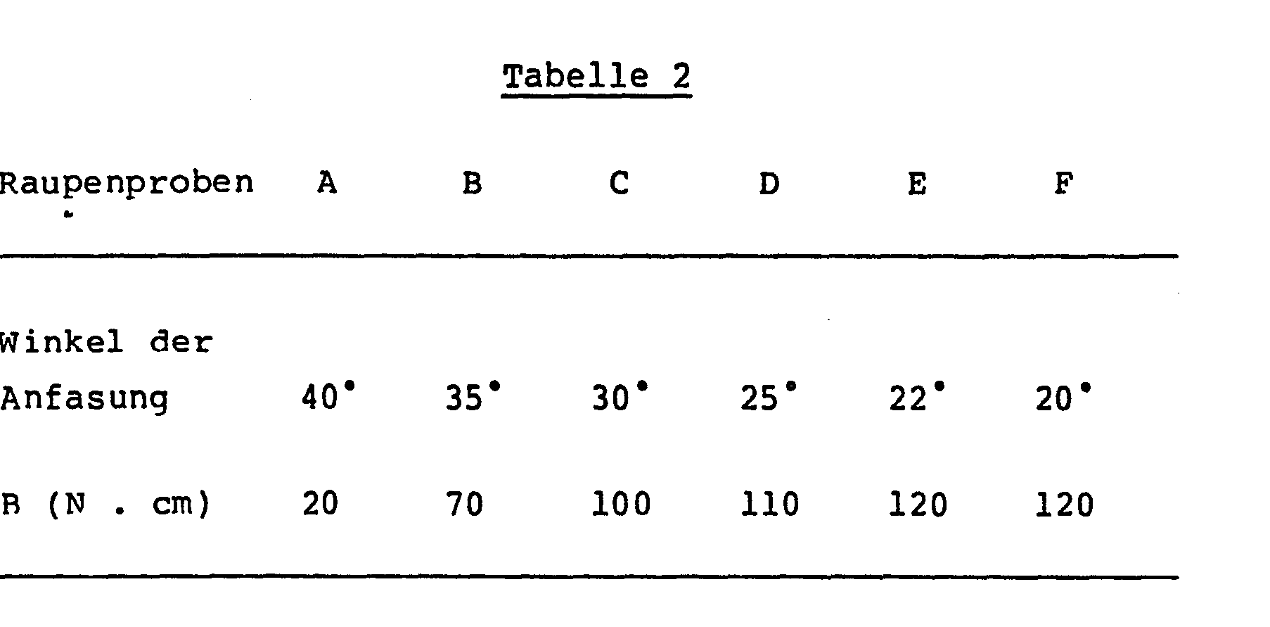
Die optimale Bruchfestigkeit liegt bei Neigungswinkeln von kleiner als 35°, insbesondere zwischen 30 und 20°.The optimum breaking strength is at angles of inclination of less than 35 °, in particular between 30 and 20 °.
Man stellt gemäß Beispiel 1 verklebte Schläuche vom Kaliber 43 mm her, wobei unterschiedlich breit geschnittene Bahnen (Tabelle 3) mit einem Flächengewicht von 50 g/m2, einem Wassergehalt von 8 % und einem Glyceringehalt von 16 % verwendet werden. Man erhält Schläuche mit verschiedener Breite der Nahtzone; die Kleberantragsbreite beträgt ca. 90-100 % der jeweiligen Überlappungsbreite (= Nahtzone). M an produces, according to Example 1, glued hoses with a caliber of 43 mm, using webs of different widths (Table 3) with a basis weight of 50 g / m2, a water content of 8% and a glycerin content of 16%. Hoses with different widths of the seam zone are obtained; the adhesive application width is approx. 90-100% of the respective overlap width (= seam zone).
Die Schläuche werden mit einer Geschwindigkeit von 160 m/min in eine Raffmaschine (US-A-4,185,358) gefördert, deren hülsenförmiges Raffelement mit URF = 5 333 Umdrehungen/min und deren Raffdorn (Durchmesser 27 mm) mit einer Drehzahl Ug von 278 Umdrehungen/ min rotieren.The hoses are conveyed at a speed of 160 m / min into a shirring machine (US-A-4,185,358), the sleeve-shaped shirring element with U RF = 5 333 revolutions / min and the shirring mandrel (

Man erhält Raupen mit einem Außendurchmesser von 43 mm, einer Innenbohrung vom Kaliber 27 mm, einer Raffdichte von 100 und einer Steigung der gewendelten Nahtzone auf der Raupe (= Wendelabstand) von 5,75 mm.This gives beads with an outer diameter of 43 mm, an inner bore of
Die Raupe D besitzt als einzige die ideale Verlagerung der Überlappung und ist in dieser Versuchsreihe die beste Raupe hinsichtlich gleichmäßigem Aussehen und Festigkeit.The caterpillar D is the only one which has the ideal displacement of the overlap and is the best caterpillar in this test series with regard to uniform appearance and strength.
Beim Füllen mit Fleischwurstmasse erweisen sich ihre günstigen Gebrauchseigenschaften.When filling with meat sausage mass, its favorable properties of use prove.
Nach Räuchern und Brühen erhält man wohlaussehende Würste vom Fleischwursttyp mit einer Ausnahme: An Würgten aus der Raupe A haben sich die Nähte infolge der thermischen und mechanischen Belastungen bei der Aufarbeitung geöffnet. Die Nahtbreite ist mit 0,5 mm zu gering, um eine ausreichende Bruchfestigkeit zu gewährleisten.After smoking and broths obtained good-looking sausages of the sausage type with one exception: At Wür g th from the caterpillar A, the seams due to thermal and mechanical loads have opened in the workup. The seam width of 0.5 mm is too small to ensure sufficient breaking strength.
Die Erfindung wird durch die Fig. 1 bis 7 näher erläutert. Es zeigt:
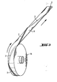
- Fig. 1 ein Beispiel für die geraffte Wursthülle,
- Fig. la einen vergrößerten Ausschnitt der gerafften Wursthülle nach Fig. 1 etwa in deren Bereich Ia
- Fig. lb einen Schnitt nach Linie Ib-Ib der Fig. la
- Fig. 2 ein Verfahren zur Herstellung eines Schlauches aus einer Bahn und Aufrollen des verdrillten Schlauches,
- Fig. 3 in perspektivischer Ansicht die Wickelrolle der Fig. 4,
- Fig. 4 die Herstellung eines gerafften Schlauches unter Abrollen eines verdrillt aufgewickelten Schlauches,
- Fig. 5 das Faltenmuster einer entrafften und aufgeschnittenen Raupe,
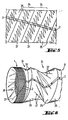
- Fig. 6 eine perspektivische Ansicht der Raupe, zum Teil im aufgezogenen Zustand,
- Fig. 7 die Anfasung mit der erfindungsgemäßen Neigung, gegen welche die Hülle zusammengeschoben werden kann.
- 1 shows an example of the gathered sausage casing,
- Fig. La shows an enlarged section of the gathered sausage casing according to Fig. 1 approximately in the area Ia
- Fig. Lb shows a section along line Ib-Ib of Fig. La
- 2 shows a method for producing a hose from a web and rolling up the twisted hose,
- 3 is a perspective view of the winding roll of FIG. 4,
- 4 the production of a shirred hose while unrolling a twisted wound hose,
- 5 the fold pattern of a draped and cut open caterpillar,
- 6 is a perspective view of the caterpillar, partly in the opened state,
- Fig. 7 shows the chamfer with the inclination according to the invention, against which the sleeve can be pushed together.
In Fig. 1 zeigt die geraffte Schlauchhülle 1 eine gewendelte Nahtzone 2 mit gleichmäßiger Steigung. Der gestrichelt gezeichnete Teil der Nahtzone 2 befindet sich in der Doppellage 25 zwischen zwei Windungen der Hauptfalte 24. Mit 28 ist der Hohlkanal der Raupe bezeichnet. Die in der Fig. la und lb ausschnittsweise und vergrößert dargestellte Raupe 1 wird in etwas aufgezogenem Zustand gezeigt.In Fig. 1 the shirred
In Fig. 2 wird die Bahn 4 aus Cellulose von einer Rolle 3 abgewickelt, durch eine Formschablone 5 geführt und mit dem Stützrohr 7 und der Hülse 8 zu einem Schlauch 6 geformt, wobei sich die beiden Ränder in der Formschablone 5 nähern. Das Stützrohr 7 und die Hülse 8 dienen zur Unterstützung der Schlauchbildung, wobei der Schlauch von innen und außen abgestützt wird.In Fig. 2, the web 4 of cellulose is unwound from a
Die Auftragseinrichtung 9 erzeugt mit einer Düse 11 einen streifenförmigen Auftrag der Klebstofflösung 10 zwischen den sich überlappenden Randzonen der Bahn 4. Nach Durchlaufen der Zugwalzen 12, 12' und Umlenkwalzen 13 wird der Schlauch zwischen zwei Quetschwalzenpaaren 14, 14' und 15, 15' aufgeblasen und mit der Rolle 16 aufgewickelt.The
Das Quetschwalzenpaar 15, 15' und die Rolle 16 befinden sich auf einem gemeinsamen Gestell 17, welches,mit dem Antriebsmotor 18 gedreht wird, wodurch die Schlauchnaht 2 in verdrillter Form auf der Rolle 16 aufgewickelt wird.The
In Fig. 3 und 4 haben die Bezugsziffern die gleiche Bedeutung wie in den vorhergehenden Figuren. In der Fig. 4 wird der verdrillt aufgewickelte Schlauch 6 von der Rolle 16 abgewickelt und nach Durchlaufen der Quetschwalzen 19, 19' in aufgeblasenem Zustand gehalten, wobei durch den Raffdorn 20 in bekannter Weise Luft 26 eingeblasen wird. Der aufgeblähte Schlauch 6 bewegt sich durch zwei weitere angetriebene Rollen 21, 21' in Richtung auf das hülsenförmige Raffelement 22, wo der eigentliche Raffvorgang stattfindet. Mit 23 ist ein Widerlager bezeichnet, gegen das der Schlauch zur Raupe 1 zusammengepreßt wird.3 and 4, the reference numerals have the same loading interpretation as in the previous figures. In FIG. 4, the twisted coiled
In Fig. 5 ist das Faltenmuster und der Verlauf der Nahtzone 2 dargestellt, wie es sich ergibt, wenn man die Raupe entrafft, die erhaltene Schlauchhülle in längsaxialer Richtung aufschneidet und flachlegt. Zwischen den Faltenlinien der spiralförmigen Hauptfalte 24 befinden sich die zickzackförmigen Linien der Sekundärfalte 27.In Fig. 5 the fold pattern and the course of the
In Fig. 6 ist ein Stück der Raupe 1 dargestellt, an derem einen Ende die Schlauchhülle 6 ein Stück weit abgezogen dargestellt ist.In Fig. 6, a piece of the
Die Fig. 7 zeigt das dem Widerlager 23 (Fig. 4) und der gerafften Schlauchhülle 1 zugewandte Ende 29 des spiralförmig gewundenen Vorsprungs des hülsenförmigen Raffelements 22. Der Vorsprung ist in Fig. 5 der US-A-4,185,358 mit der Bezugsziffer 21 versehen. Die vorliegende Fig. 7 dient zur Erläuterung des im Anspruch 3 genannten Winkels a zwischen der Fläche der Raffalte, die sich von der Windung der Hauptfalte 24 bis zur Innenfläche der Raupe im Hohlkanal 28 erstreckt und der Raupenlängsachse bzw. dem Winkel a der Anfasung 30. Der Winkel a läßt sich ermitteln aus der Faltenhöhe h, die sich aus der halben Differenz des äußeren und inneren Durchmessers Da bzw. Di der Raupe ergibt, und der Länge Lf der Raffalte. Es gilt dabei die Beziehung
Die genannte Fläche der Raffalte bildet eine Kegelstumpfmantelfläche zur längsaxialen Drehachse und zeigt die Neigung der Doppellage 25, die sich zwischen zwei benachbarten Windungen der Hauptfalte 24 befindet.The aforementioned surface of the gathering pleat forms a truncated cone surface to the longitudinal axis of rotation and shows the inclination of the
Die geraffte Wursthülle der Erfindung ist - trotz der Verdickung, z.B. in Form einer Klebenaht - gleichmäßig ausgebildet, besitzt einen geraden inneren Hohlkanal mit gleichmäßigem kreisförmigem großem Querschnitt, zeigt hohe Steifigkeit und Bruchfestigkeit. Die Falten werden fest und eng zusammengehalten. Die Wursthülle gestattet sicheres Hantieren beim Transport und läßt sich problemlos an schnell arbeitenden Füllmaschinen einsetzen. Der große Querschnitt des Hohlkanals erlaubt die Verwendung von Füllrohren mit großen Durchmessern, wodurch die Wursthülle schneller mit Wurstmasse gestopft werden kann.The gathered sausage casing of the invention is - despite the thickening, e.g. in the form of an adhesive seam - evenly formed, has a straight inner hollow channel with a uniform circular large cross-section, shows high rigidity and breaking strength. The folds are held tight and tight. The sausage casing allows safe handling during transport and can be easily used on fast-working filling machines. The large cross-section of the hollow channel allows the use of filling pipes with large diameters, which means that the sausage casing can be stuffed with sausage mass more quickly.
Claims (16)
Applications Claiming Priority (2)
| Application Number | Priority Date | Filing Date | Title |
|---|---|---|---|
| DE3228675 | 1982-07-31 | ||
| DE19823228675 DE3228675A1 (en) | 1982-07-31 | 1982-07-31 | GATHERED SAUSAGE CASE AND METHOD FOR THEIR PRODUCTION |
Publications (1)
| Publication Number | Publication Date |
|---|---|
| EP0100495A1 true EP0100495A1 (en) | 1984-02-15 |
Family
ID=6169831
Family Applications (1)
| Application Number | Title | Priority Date | Filing Date |
|---|---|---|---|
| EP83107196A Withdrawn EP0100495A1 (en) | 1982-07-31 | 1983-07-22 | Shirred sausage casing and method for its production |
Country Status (5)
| Country | Link |
|---|---|
| US (1) | US4550042A (en) |
| EP (1) | EP0100495A1 (en) |
| JP (1) | JPS5928435A (en) |
| DE (1) | DE3228675A1 (en) |
| FI (1) | FI832738L (en) |
Cited By (3)
| Publication number | Priority date | Publication date | Assignee | Title |
|---|---|---|---|---|
| EP0093326A3 (en) * | 1982-05-03 | 1985-03-27 | Hoechst Aktiengesellschaft | Shirred sausage casing and method of making it |
| EP0149839A3 (en) * | 1984-01-20 | 1985-08-21 | Hoechst Aktiengesellschaft | Use of a shirred casing |
| EP0166226A1 (en) * | 1984-06-26 | 1986-01-02 | Kollross, Günter | A method for the production of a tubular casing shirred to form a bellows-like hollow body, for further processing as a peelable skin in the manufacture of sausages, and casing produced thereby |
Families Citing this family (10)
| Publication number | Priority date | Publication date | Assignee | Title |
|---|---|---|---|---|
| US4756057A (en) * | 1981-07-17 | 1988-07-12 | Viskase Corporation | Method of making high coherency shirred casing |
| US4660255A (en) * | 1985-05-08 | 1987-04-28 | Townsend Ray T | Method and apparatus for encasing a product |
| US4727625A (en) * | 1985-05-08 | 1988-03-01 | Townsend Engineering Company | Encased product and method and apparatus for encasing same |
| US4944069A (en) * | 1988-04-28 | 1990-07-31 | Townsend Engineering Company | Encased product and method and apparatus for encasing same |
| US4885821A (en) * | 1988-08-01 | 1989-12-12 | Viskase Corporation | Method and apparatus for severing shirred tubular food casing and article |
| US5203734A (en) * | 1990-08-28 | 1993-04-20 | Teepak, Inc. | Food casings with improved tubular tab ends |
| DE10049178A1 (en) * | 2000-10-05 | 2002-04-11 | Guenter Kollross | Ruched tubular film and method and device for gathering |
| US7507150B2 (en) * | 2004-08-23 | 2009-03-24 | Visko Teepak Belgium Nv | Shirred casing |
| CA118257S (en) * | 2006-05-15 | 2008-01-02 | Filtercorp Internat Ltd | Tube for receiving a flexible connector at its profiled end |
| CA118256S (en) * | 2006-05-15 | 2008-01-02 | Filtercorp Internat Ltd | Flexible tubular connector with self supporting end bands |
Citations (9)
| Publication number | Priority date | Publication date | Assignee | Title |
|---|---|---|---|---|
| DE1288944B (en) * | 1966-10-01 | 1969-02-06 | Kalle Ag | Method for shirring artificial sausage casings |
| US3619854A (en) * | 1966-10-01 | 1971-11-16 | Kalle Ag | Process for shirring artificial sausage casings |
| US3766603A (en) * | 1964-12-15 | 1973-10-23 | Union Carbide Corp | Shirred tubing, method and apparatus for making same |
| US3907003A (en) * | 1972-07-26 | 1975-09-23 | Kalle Ag | Shirred sausage casings and method and apparatus for making same |
| US4185358A (en) * | 1971-09-23 | 1980-01-29 | Hoechst Aktiengesellschaft | Apparatus for shirring casings |
| FR2437295A1 (en) * | 1978-09-29 | 1980-04-25 | Union Carbide Corp | METHOD AND APPARATUS FOR PLEATING A FLEXIBLE TUBE |
| EP0037543A2 (en) * | 1980-04-05 | 1981-10-14 | Hoechst Aktiengesellschaft | Tubular casings with an adhesive seam for foodstuffs, especially sausages, and process for its manufacture |
| EP0054162A1 (en) * | 1980-11-29 | 1982-06-23 | Hoechst Aktiengesellschaft | Tubular casing, especially for sausage casings, containing a coating impermeable to water vapour, process for its production and use thereof |
| EP0073321A2 (en) * | 1981-07-17 | 1983-03-09 | Viskase Corporation | High coherency shirred casings |
Family Cites Families (2)
| Publication number | Priority date | Publication date | Assignee | Title |
|---|---|---|---|---|
| NL198636A (en) * | 1954-07-07 | |||
| FR96372E (en) * | 1967-12-27 | 1972-06-16 |
-
1982
- 1982-07-31 DE DE19823228675 patent/DE3228675A1/en not_active Withdrawn
-
1983
- 1983-07-07 JP JP58122460A patent/JPS5928435A/en active Pending
- 1983-07-22 EP EP83107196A patent/EP0100495A1/en not_active Withdrawn
- 1983-07-25 US US06/516,984 patent/US4550042A/en not_active Expired - Fee Related
- 1983-07-28 FI FI832738A patent/FI832738L/en not_active Application Discontinuation
Patent Citations (9)
| Publication number | Priority date | Publication date | Assignee | Title |
|---|---|---|---|---|
| US3766603A (en) * | 1964-12-15 | 1973-10-23 | Union Carbide Corp | Shirred tubing, method and apparatus for making same |
| DE1288944B (en) * | 1966-10-01 | 1969-02-06 | Kalle Ag | Method for shirring artificial sausage casings |
| US3619854A (en) * | 1966-10-01 | 1971-11-16 | Kalle Ag | Process for shirring artificial sausage casings |
| US4185358A (en) * | 1971-09-23 | 1980-01-29 | Hoechst Aktiengesellschaft | Apparatus for shirring casings |
| US3907003A (en) * | 1972-07-26 | 1975-09-23 | Kalle Ag | Shirred sausage casings and method and apparatus for making same |
| FR2437295A1 (en) * | 1978-09-29 | 1980-04-25 | Union Carbide Corp | METHOD AND APPARATUS FOR PLEATING A FLEXIBLE TUBE |
| EP0037543A2 (en) * | 1980-04-05 | 1981-10-14 | Hoechst Aktiengesellschaft | Tubular casings with an adhesive seam for foodstuffs, especially sausages, and process for its manufacture |
| EP0054162A1 (en) * | 1980-11-29 | 1982-06-23 | Hoechst Aktiengesellschaft | Tubular casing, especially for sausage casings, containing a coating impermeable to water vapour, process for its production and use thereof |
| EP0073321A2 (en) * | 1981-07-17 | 1983-03-09 | Viskase Corporation | High coherency shirred casings |
Cited By (3)
| Publication number | Priority date | Publication date | Assignee | Title |
|---|---|---|---|---|
| EP0093326A3 (en) * | 1982-05-03 | 1985-03-27 | Hoechst Aktiengesellschaft | Shirred sausage casing and method of making it |
| EP0149839A3 (en) * | 1984-01-20 | 1985-08-21 | Hoechst Aktiengesellschaft | Use of a shirred casing |
| EP0166226A1 (en) * | 1984-06-26 | 1986-01-02 | Kollross, Günter | A method for the production of a tubular casing shirred to form a bellows-like hollow body, for further processing as a peelable skin in the manufacture of sausages, and casing produced thereby |
Also Published As
| Publication number | Publication date |
|---|---|
| FI832738A0 (en) | 1983-07-28 |
| FI832738A7 (en) | 1984-02-01 |
| JPS5928435A (en) | 1984-02-15 |
| FI832738L (en) | 1984-02-01 |
| DE3228675A1 (en) | 1984-04-12 |
| US4550042A (en) | 1985-10-29 |
Similar Documents
| Publication | Publication Date | Title |
|---|---|---|
| EP0080120B1 (en) | Apparatus for shaping a tube from a flat web | |
| EP0101892B1 (en) | Peelable sausage casing with an adhesive seam, process for its manufacture and its use | |
| EP0076436B1 (en) | Tubular casing for smokable foodstuffs, especially smokable sausages, process for its manufacture and use thereof | |
| DE1632137C3 (en) | Method and device for crimping sausage casings | |
| EP0100495A1 (en) | Shirred sausage casing and method for its production | |
| DE2360481C3 (en) | Hollow rod closed on one side made of a shirred tubular casing with an end closure formed from unfolded tubular casing and a method for producing the closure located in the rod cavity | |
| DE2939318C2 (en) | Device for shirring tubular food casings | |
| EP0093326B1 (en) | Shirred sausage casing and method of making it | |
| DE69410713T2 (en) | Method for wrapping a fiber bundle | |
| EP0944524B1 (en) | Manufacture of an endless plastic pipe | |
| DE1954103A1 (en) | Method and device for shirring endless extruded tubes | |
| DE2556332A1 (en) | Production of double walled paper tubes for cigarettes - paper band is folded and formed into tube | |
| DE2309721C2 (en) | Method and device for shirring tubular casings | |
| DE1093546B (en) | Process for the production of internally smooth hoses made of thermoplastic material with a support helix using the winding method | |
| CH673932A5 (en) | ||
| DE2309720C2 (en) | Method and device for shirring tubular casings | |
| EP0101986B1 (en) | Shirred casing, shirring organ for making it and device with this shirring organ | |
| DE3913661C2 (en) | Process for making a wrapped product | |
| EP0149839A2 (en) | Use of a shirred casing | |
| EP0287939A2 (en) | Hose, especially sausage cover, consisting out of different sections connected to each other | |
| EP0267473B1 (en) | Method and device for shirring tubular casings, especially sausage casings | |
| DE2236600C2 (en) | Ruched sausage casing | |
| DE2555122C3 (en) | Method of joining flexible tubular pieces | |
| DE2318457C3 (en) | Hollow rod made of a shirred casing with an internal end closure formed from the casing material itself in the form of a hose roll designed as a roll and a process for its production | |
| DE2147498A1 (en) | Tubular sleeve corrugator - for compaction of eg sausage skins for transport |
Legal Events
| Date | Code | Title | Description |
|---|---|---|---|
| PUAI | Public reference made under article 153(3) epc to a published international application that has entered the european phase |
Free format text: ORIGINAL CODE: 0009012 |
|
| AK | Designated contracting states |
Designated state(s): AT BE CH DE FR GB IT LI LU NL SE |
|
| 17P | Request for examination filed |
Effective date: 19840608 |
|
| STAA | Information on the status of an ep patent application or granted ep patent |
Free format text: STATUS: THE APPLICATION HAS BEEN WITHDRAWN |
|
| 18W | Application withdrawn |
Withdrawal date: 19870210 |
|
| RIN1 | Information on inventor provided before grant (corrected) |
Inventor name: ANDRAE, KLAUS, DR. Inventor name: HUTSCHENREUTER, ELFRIEDE |