EP0100371B1 - Fortschreitendes Fliesscracken von Kohle/Öl-Mischungen mit Katalysatoren hohen Metallgehaltes - Google Patents
Fortschreitendes Fliesscracken von Kohle/Öl-Mischungen mit Katalysatoren hohen Metallgehaltes Download PDFInfo
- Publication number
- EP0100371B1 EP0100371B1 EP82106973A EP82106973A EP0100371B1 EP 0100371 B1 EP0100371 B1 EP 0100371B1 EP 82106973 A EP82106973 A EP 82106973A EP 82106973 A EP82106973 A EP 82106973A EP 0100371 B1 EP0100371 B1 EP 0100371B1
- Authority
- EP
- European Patent Office
- Prior art keywords
- catalyst
- range
- oil
- coal
- zone
- Prior art date
- Legal status (The legal status is an assumption and is not a legal conclusion. Google has not performed a legal analysis and makes no representation as to the accuracy of the status listed.)
- Expired
Links
- 239000003054 catalyst Substances 0.000 title claims abstract description 505
- 238000005336 cracking Methods 0.000 title claims abstract description 93
- 229910052751 metal Inorganic materials 0.000 title claims abstract description 67
- 239000002184 metal Substances 0.000 title claims abstract description 67
- 239000003245 coal Substances 0.000 title claims abstract description 61
- 150000002739 metals Chemical class 0.000 title claims abstract description 45
- 230000000750 progressive effect Effects 0.000 title claims abstract description 22
- 239000000203 mixture Substances 0.000 title claims description 37
- 238000006243 chemical reaction Methods 0.000 claims abstract description 136
- 238000000034 method Methods 0.000 claims abstract description 109
- PXHVJJICTQNCMI-UHFFFAOYSA-N Nickel Chemical compound [Ni] PXHVJJICTQNCMI-UHFFFAOYSA-N 0.000 claims abstract description 93
- 239000000463 material Substances 0.000 claims abstract description 93
- 230000008569 process Effects 0.000 claims abstract description 86
- 229910001385 heavy metal Inorganic materials 0.000 claims abstract description 58
- 229910052759 nickel Inorganic materials 0.000 claims abstract description 47
- UFHFLCQGNIYNRP-UHFFFAOYSA-N Hydrogen Chemical compound [H][H] UFHFLCQGNIYNRP-UHFFFAOYSA-N 0.000 claims abstract description 40
- 229910052739 hydrogen Inorganic materials 0.000 claims abstract description 37
- 239000001257 hydrogen Substances 0.000 claims abstract description 37
- 238000006356 dehydrogenation reaction Methods 0.000 claims abstract description 16
- 239000000852 hydrogen donor Substances 0.000 claims abstract description 15
- 239000000047 product Substances 0.000 claims description 90
- 239000000571 coke Substances 0.000 claims description 66
- 239000007789 gas Substances 0.000 claims description 65
- 230000008929 regeneration Effects 0.000 claims description 63
- 238000011069 regeneration method Methods 0.000 claims description 63
- OKTJSMMVPCPJKN-UHFFFAOYSA-N Carbon Chemical group [C] OKTJSMMVPCPJKN-UHFFFAOYSA-N 0.000 claims description 62
- XLYOFNOQVPJJNP-UHFFFAOYSA-N water Substances O XLYOFNOQVPJJNP-UHFFFAOYSA-N 0.000 claims description 59
- 229910052799 carbon Inorganic materials 0.000 claims description 52
- 229930195733 hydrocarbon Natural products 0.000 claims description 47
- 150000002430 hydrocarbons Chemical class 0.000 claims description 47
- 239000004215 Carbon black (E152) Substances 0.000 claims description 42
- 239000007788 liquid Substances 0.000 claims description 33
- QVGXLLKOCUKJST-UHFFFAOYSA-N atomic oxygen Chemical compound [O] QVGXLLKOCUKJST-UHFFFAOYSA-N 0.000 claims description 29
- 229910052760 oxygen Inorganic materials 0.000 claims description 29
- 239000001301 oxygen Substances 0.000 claims description 29
- 238000002485 combustion reaction Methods 0.000 claims description 22
- 230000036961 partial effect Effects 0.000 claims description 20
- 238000004519 manufacturing process Methods 0.000 claims description 17
- 238000004523 catalytic cracking Methods 0.000 claims description 16
- 230000002829 reductive effect Effects 0.000 claims description 15
- 239000011148 porous material Substances 0.000 claims description 14
- 239000012263 liquid product Substances 0.000 claims description 13
- 230000001737 promoting effect Effects 0.000 claims description 12
- 238000000197 pyrolysis Methods 0.000 claims description 10
- RWSOTUBLDIXVET-UHFFFAOYSA-N Dihydrogen sulfide Chemical compound S RWSOTUBLDIXVET-UHFFFAOYSA-N 0.000 claims description 8
- 239000012298 atmosphere Substances 0.000 claims description 8
- 239000000446 fuel Substances 0.000 claims description 8
- 229910000037 hydrogen sulfide Inorganic materials 0.000 claims description 8
- 238000004231 fluid catalytic cracking Methods 0.000 claims description 6
- 239000003830 anthracite Substances 0.000 claims description 5
- 229910002091 carbon monoxide Inorganic materials 0.000 claims description 4
- 239000003077 lignite Substances 0.000 claims description 4
- 230000001172 regenerating effect Effects 0.000 claims description 4
- 239000003415 peat Substances 0.000 claims description 2
- 238000004064 recycling Methods 0.000 claims description 2
- 238000000629 steam reforming Methods 0.000 claims 1
- 238000005984 hydrogenation reaction Methods 0.000 abstract description 4
- 239000003921 oil Substances 0.000 description 154
- 239000010457 zeolite Substances 0.000 description 53
- 230000000694 effects Effects 0.000 description 51
- HNPSIPDUKPIQMN-UHFFFAOYSA-N dioxosilane;oxo(oxoalumanyloxy)alumane Chemical compound O=[Si]=O.O=[Al]O[Al]=O HNPSIPDUKPIQMN-UHFFFAOYSA-N 0.000 description 49
- 239000002245 particle Substances 0.000 description 43
- 229910021536 Zeolite Inorganic materials 0.000 description 41
- 238000000926 separation method Methods 0.000 description 28
- 230000035508 accumulation Effects 0.000 description 20
- 238000009825 accumulation Methods 0.000 description 20
- 238000009835 boiling Methods 0.000 description 20
- 238000011144 upstream manufacturing Methods 0.000 description 19
- IJGRMHOSHXDMSA-UHFFFAOYSA-N Atomic nitrogen Chemical compound N#N IJGRMHOSHXDMSA-UHFFFAOYSA-N 0.000 description 18
- 230000008901 benefit Effects 0.000 description 18
- 229910002092 carbon dioxide Inorganic materials 0.000 description 17
- 238000012545 processing Methods 0.000 description 15
- 239000010779 crude oil Substances 0.000 description 14
- NINIDFKCEFEMDL-UHFFFAOYSA-N Sulfur Chemical compound [S] NINIDFKCEFEMDL-UHFFFAOYSA-N 0.000 description 13
- CURLTUGMZLYLDI-UHFFFAOYSA-N Carbon dioxide Chemical compound O=C=O CURLTUGMZLYLDI-UHFFFAOYSA-N 0.000 description 12
- 230000001965 increasing effect Effects 0.000 description 11
- 229910052717 sulfur Inorganic materials 0.000 description 11
- 239000011593 sulfur Substances 0.000 description 11
- 238000012360 testing method Methods 0.000 description 11
- 230000001276 controlling effect Effects 0.000 description 10
- 230000000607 poisoning effect Effects 0.000 description 10
- 229910052720 vanadium Inorganic materials 0.000 description 10
- 239000000654 additive Substances 0.000 description 9
- 229910052784 alkaline earth metal Inorganic materials 0.000 description 9
- 230000009286 beneficial effect Effects 0.000 description 9
- 230000003197 catalytic effect Effects 0.000 description 9
- 230000006870 function Effects 0.000 description 9
- 239000003502 gasoline Substances 0.000 description 9
- 239000011159 matrix material Substances 0.000 description 9
- 229910052757 nitrogen Inorganic materials 0.000 description 9
- 230000009467 reduction Effects 0.000 description 9
- LEONUFNNVUYDNQ-UHFFFAOYSA-N vanadium atom Chemical compound [V] LEONUFNNVUYDNQ-UHFFFAOYSA-N 0.000 description 9
- 230000008016 vaporization Effects 0.000 description 9
- QCWXUUIWCKQGHC-UHFFFAOYSA-N Zirconium Chemical group [Zr] QCWXUUIWCKQGHC-UHFFFAOYSA-N 0.000 description 8
- 239000013078 crystal Substances 0.000 description 8
- VNWKTOKETHGBQD-UHFFFAOYSA-N methane Chemical compound C VNWKTOKETHGBQD-UHFFFAOYSA-N 0.000 description 8
- 229910052708 sodium Inorganic materials 0.000 description 8
- 239000011734 sodium Substances 0.000 description 8
- -1 sub- anthracite Chemical compound 0.000 description 8
- 229910052726 zirconium Chemical group 0.000 description 8
- UGFAIRIUMAVXCW-UHFFFAOYSA-N Carbon monoxide Chemical compound [O+]#[C-] UGFAIRIUMAVXCW-UHFFFAOYSA-N 0.000 description 7
- DGAQECJNVWCQMB-PUAWFVPOSA-M Ilexoside XXIX Chemical compound C[C@@H]1CC[C@@]2(CC[C@@]3(C(=CC[C@H]4[C@]3(CC[C@@H]5[C@@]4(CC[C@@H](C5(C)C)OS(=O)(=O)[O-])C)C)[C@@H]2[C@]1(C)O)C)C(=O)O[C@H]6[C@@H]([C@H]([C@@H]([C@H](O6)CO)O)O)O.[Na+] DGAQECJNVWCQMB-PUAWFVPOSA-M 0.000 description 7
- XEEYBQQBJWHFJM-UHFFFAOYSA-N Iron Chemical compound [Fe] XEEYBQQBJWHFJM-UHFFFAOYSA-N 0.000 description 7
- RTAQQCXQSZGOHL-UHFFFAOYSA-N Titanium Chemical group [Ti] RTAQQCXQSZGOHL-UHFFFAOYSA-N 0.000 description 7
- 229910000323 aluminium silicate Inorganic materials 0.000 description 7
- 150000001875 compounds Chemical class 0.000 description 7
- 230000009849 deactivation Effects 0.000 description 7
- 230000007423 decrease Effects 0.000 description 7
- 229910052719 titanium Inorganic materials 0.000 description 7
- 239000010936 titanium Substances 0.000 description 7
- 238000012546 transfer Methods 0.000 description 7
- 229910052770 Uranium Inorganic materials 0.000 description 6
- 150000001342 alkaline earth metals Chemical class 0.000 description 6
- 238000004939 coking Methods 0.000 description 6
- 239000003546 flue gas Substances 0.000 description 6
- 239000012530 fluid Substances 0.000 description 6
- 239000011261 inert gas Substances 0.000 description 6
- 238000011068 loading method Methods 0.000 description 6
- 239000003208 petroleum Substances 0.000 description 6
- 239000007787 solid Substances 0.000 description 6
- 238000011282 treatment Methods 0.000 description 6
- 239000003513 alkali Substances 0.000 description 5
- 125000003118 aryl group Chemical group 0.000 description 5
- 230000015572 biosynthetic process Effects 0.000 description 5
- 238000009833 condensation Methods 0.000 description 5
- 239000012084 conversion product Substances 0.000 description 5
- 239000006185 dispersion Substances 0.000 description 5
- 238000004821 distillation Methods 0.000 description 5
- 239000002808 molecular sieve Substances 0.000 description 5
- 230000001590 oxidative effect Effects 0.000 description 5
- 231100000572 poisoning Toxicity 0.000 description 5
- URGAHOPLAPQHLN-UHFFFAOYSA-N sodium aluminosilicate Chemical compound [Na+].[Al+3].[O-][Si]([O-])=O.[O-][Si]([O-])=O URGAHOPLAPQHLN-UHFFFAOYSA-N 0.000 description 5
- 238000009834 vaporization Methods 0.000 description 5
- VYPSYNLAJGMNEJ-UHFFFAOYSA-N Silicium dioxide Chemical compound O=[Si]=O VYPSYNLAJGMNEJ-UHFFFAOYSA-N 0.000 description 4
- 238000010521 absorption reaction Methods 0.000 description 4
- 239000001569 carbon dioxide Substances 0.000 description 4
- 230000005494 condensation Effects 0.000 description 4
- 229910052802 copper Inorganic materials 0.000 description 4
- 239000010949 copper Substances 0.000 description 4
- 230000002950 deficient Effects 0.000 description 4
- 239000000284 extract Substances 0.000 description 4
- 239000012013 faujasite Substances 0.000 description 4
- 229910052742 iron Inorganic materials 0.000 description 4
- 239000002243 precursor Substances 0.000 description 4
- 239000011949 solid catalyst Substances 0.000 description 4
- 238000001179 sorption measurement Methods 0.000 description 4
- 238000005292 vacuum distillation Methods 0.000 description 4
- RYGMFSIKBFXOCR-UHFFFAOYSA-N Copper Chemical compound [Cu] RYGMFSIKBFXOCR-UHFFFAOYSA-N 0.000 description 3
- XUIMIQQOPSSXEZ-UHFFFAOYSA-N Silicon Chemical group [Si] XUIMIQQOPSSXEZ-UHFFFAOYSA-N 0.000 description 3
- UCKMPCXJQFINFW-UHFFFAOYSA-N Sulphide Chemical compound [S-2] UCKMPCXJQFINFW-UHFFFAOYSA-N 0.000 description 3
- 230000000996 additive effect Effects 0.000 description 3
- RHZUVFJBSILHOK-UHFFFAOYSA-N anthracen-1-ylmethanolate Chemical compound C1=CC=C2C=C3C(C[O-])=CC=CC3=CC2=C1 RHZUVFJBSILHOK-UHFFFAOYSA-N 0.000 description 3
- 239000000470 constituent Substances 0.000 description 3
- 239000000356 contaminant Substances 0.000 description 3
- 230000003247 decreasing effect Effects 0.000 description 3
- 239000003085 diluting agent Substances 0.000 description 3
- 230000005484 gravity Effects 0.000 description 3
- 238000002156 mixing Methods 0.000 description 3
- TVMXDCGIABBOFY-UHFFFAOYSA-N octane Chemical compound CCCCCCCC TVMXDCGIABBOFY-UHFFFAOYSA-N 0.000 description 3
- 230000003647 oxidation Effects 0.000 description 3
- 238000007254 oxidation reaction Methods 0.000 description 3
- 239000000523 sample Substances 0.000 description 3
- 239000007921 spray Substances 0.000 description 3
- 239000000126 substance Substances 0.000 description 3
- 239000000725 suspension Substances 0.000 description 3
- 239000011269 tar Substances 0.000 description 3
- CXWXQJXEFPUFDZ-UHFFFAOYSA-N tetralin Chemical compound C1=CC=C2CCCCC2=C1 CXWXQJXEFPUFDZ-UHFFFAOYSA-N 0.000 description 3
- YZCKVEUIGOORGS-UHFFFAOYSA-N Hydrogen atom Chemical compound [H] YZCKVEUIGOORGS-UHFFFAOYSA-N 0.000 description 2
- CPLXHLVBOLITMK-UHFFFAOYSA-N Magnesium oxide Chemical compound [Mg]=O CPLXHLVBOLITMK-UHFFFAOYSA-N 0.000 description 2
- OFBQJSOFQDEBGM-UHFFFAOYSA-N Pentane Chemical compound CCCCC OFBQJSOFQDEBGM-UHFFFAOYSA-N 0.000 description 2
- 150000001298 alcohols Chemical class 0.000 description 2
- 229910052782 aluminium Inorganic materials 0.000 description 2
- XAGFODPZIPBFFR-UHFFFAOYSA-N aluminium Chemical compound [Al] XAGFODPZIPBFFR-UHFFFAOYSA-N 0.000 description 2
- PNEYBMLMFCGWSK-UHFFFAOYSA-N aluminium oxide Inorganic materials [O-2].[O-2].[O-2].[Al+3].[Al+3] PNEYBMLMFCGWSK-UHFFFAOYSA-N 0.000 description 2
- 239000010426 asphalt Substances 0.000 description 2
- 239000006227 byproduct Substances 0.000 description 2
- 239000000969 carrier Substances 0.000 description 2
- 150000001768 cations Chemical class 0.000 description 2
- 230000008859 change Effects 0.000 description 2
- 230000001427 coherent effect Effects 0.000 description 2
- 239000000567 combustion gas Substances 0.000 description 2
- 238000004891 communication Methods 0.000 description 2
- 238000011109 contamination Methods 0.000 description 2
- 238000001816 cooling Methods 0.000 description 2
- 239000012809 cooling fluid Substances 0.000 description 2
- NNBZCPXTIHJBJL-UHFFFAOYSA-N decalin Chemical compound C1CCCC2CCCCC21 NNBZCPXTIHJBJL-UHFFFAOYSA-N 0.000 description 2
- 238000007324 demetalation reaction Methods 0.000 description 2
- 230000008021 deposition Effects 0.000 description 2
- 238000011033 desalting Methods 0.000 description 2
- 238000013461 design Methods 0.000 description 2
- 238000006477 desulfuration reaction Methods 0.000 description 2
- 230000023556 desulfurization Effects 0.000 description 2
- 238000009792 diffusion process Methods 0.000 description 2
- 238000007599 discharging Methods 0.000 description 2
- 238000004090 dissolution Methods 0.000 description 2
- 238000011143 downstream manufacturing Methods 0.000 description 2
- 238000005243 fluidization Methods 0.000 description 2
- 238000010438 heat treatment Methods 0.000 description 2
- 150000002431 hydrogen Chemical class 0.000 description 2
- 229910052809 inorganic oxide Inorganic materials 0.000 description 2
- 238000005342 ion exchange Methods 0.000 description 2
- 150000002736 metal compounds Chemical class 0.000 description 2
- 229910044991 metal oxide Inorganic materials 0.000 description 2
- 150000004706 metal oxides Chemical class 0.000 description 2
- 230000004048 modification Effects 0.000 description 2
- 238000012986 modification Methods 0.000 description 2
- QJGQUHMNIGDVPM-UHFFFAOYSA-N nitrogen group Chemical group [N] QJGQUHMNIGDVPM-UHFFFAOYSA-N 0.000 description 2
- 150000002902 organometallic compounds Chemical class 0.000 description 2
- JTJMJGYZQZDUJJ-UHFFFAOYSA-N phencyclidine Chemical class C1CCCCN1C1(C=2C=CC=CC=2)CCCCC1 JTJMJGYZQZDUJJ-UHFFFAOYSA-N 0.000 description 2
- 238000002203 pretreatment Methods 0.000 description 2
- 238000005086 pumping Methods 0.000 description 2
- 238000007670 refining Methods 0.000 description 2
- 238000011160 research Methods 0.000 description 2
- 239000011369 resultant mixture Substances 0.000 description 2
- 239000003079 shale oil Substances 0.000 description 2
- 229910052710 silicon Inorganic materials 0.000 description 2
- 239000010703 silicon Substances 0.000 description 2
- 239000000377 silicon dioxide Substances 0.000 description 2
- 239000002904 solvent Substances 0.000 description 2
- 150000004763 sulfides Chemical class 0.000 description 2
- VXUYXOFXAQZZMF-UHFFFAOYSA-N titanium(IV) isopropoxide Chemical compound CC(C)O[Ti](OC(C)C)(OC(C)C)OC(C)C VXUYXOFXAQZZMF-UHFFFAOYSA-N 0.000 description 2
- DUFCMRCMPHIFTR-UHFFFAOYSA-N 5-(dimethylsulfamoyl)-2-methylfuran-3-carboxylic acid Chemical compound CN(C)S(=O)(=O)C1=CC(C(O)=O)=C(C)O1 DUFCMRCMPHIFTR-UHFFFAOYSA-N 0.000 description 1
- 239000005995 Aluminium silicate Substances 0.000 description 1
- QGZKDVFQNNGYKY-UHFFFAOYSA-O Ammonium Chemical compound [NH4+] QGZKDVFQNNGYKY-UHFFFAOYSA-O 0.000 description 1
- 239000007848 Bronsted acid Substances 0.000 description 1
- GYHNNYVSQQEPJS-UHFFFAOYSA-N Gallium Chemical compound [Ga] GYHNNYVSQQEPJS-UHFFFAOYSA-N 0.000 description 1
- QAOWNCQODCNURD-UHFFFAOYSA-L Sulfate Chemical compound [O-]S([O-])(=O)=O QAOWNCQODCNURD-UHFFFAOYSA-L 0.000 description 1
- ATJFFYVFTNAWJD-UHFFFAOYSA-N Tin Chemical compound [Sn] ATJFFYVFTNAWJD-UHFFFAOYSA-N 0.000 description 1
- 238000005299 abrasion Methods 0.000 description 1
- 239000002253 acid Substances 0.000 description 1
- 230000009471 action Effects 0.000 description 1
- 239000002671 adjuvant Substances 0.000 description 1
- 230000002411 adverse Effects 0.000 description 1
- 239000000809 air pollutant Substances 0.000 description 1
- 231100001243 air pollutant Toxicity 0.000 description 1
- 150000001339 alkali metal compounds Chemical class 0.000 description 1
- 150000001341 alkaline earth metal compounds Chemical class 0.000 description 1
- 150000001336 alkenes Chemical class 0.000 description 1
- AZDRQVAHHNSJOQ-UHFFFAOYSA-N alumane Chemical group [AlH3] AZDRQVAHHNSJOQ-UHFFFAOYSA-N 0.000 description 1
- 235000012211 aluminium silicate Nutrition 0.000 description 1
- JEWHCPOELGJVCB-UHFFFAOYSA-N aluminum;calcium;oxido-[oxido(oxo)silyl]oxy-oxosilane;potassium;sodium;tridecahydrate Chemical compound O.O.O.O.O.O.O.O.O.O.O.O.O.[Na].[Al].[K].[Ca].[O-][Si](=O)O[Si]([O-])=O JEWHCPOELGJVCB-UHFFFAOYSA-N 0.000 description 1
- 238000004458 analytical method Methods 0.000 description 1
- 229910052787 antimony Inorganic materials 0.000 description 1
- WATWJIUSRGPENY-UHFFFAOYSA-N antimony atom Chemical compound [Sb] WATWJIUSRGPENY-UHFFFAOYSA-N 0.000 description 1
- 238000013459 approach Methods 0.000 description 1
- 125000004429 atom Chemical group 0.000 description 1
- IRERQBUNZFJFGC-UHFFFAOYSA-L azure blue Chemical compound [Na+].[Na+].[Na+].[Na+].[Na+].[Na+].[Na+].[Na+].[Al+3].[Al+3].[Al+3].[Al+3].[Al+3].[Al+3].[S-]S[S-].[O-][Si]([O-])([O-])[O-].[O-][Si]([O-])([O-])[O-].[O-][Si]([O-])([O-])[O-].[O-][Si]([O-])([O-])[O-].[O-][Si]([O-])([O-])[O-].[O-][Si]([O-])([O-])[O-] IRERQBUNZFJFGC-UHFFFAOYSA-L 0.000 description 1
- 230000004888 barrier function Effects 0.000 description 1
- 239000002585 base Substances 0.000 description 1
- 229910001423 beryllium ion Inorganic materials 0.000 description 1
- 239000012267 brine Substances 0.000 description 1
- UNYSKUBLZGJSLV-UHFFFAOYSA-L calcium;1,3,5,2,4,6$l^{2}-trioxadisilaluminane 2,4-dioxide;dihydroxide;hexahydrate Chemical compound O.O.O.O.O.O.[OH-].[OH-].[Ca+2].O=[Si]1O[Al]O[Si](=O)O1.O=[Si]1O[Al]O[Si](=O)O1 UNYSKUBLZGJSLV-UHFFFAOYSA-L 0.000 description 1
- 229910002090 carbon oxide Inorganic materials 0.000 description 1
- 150000007942 carboxylates Chemical class 0.000 description 1
- 230000015556 catabolic process Effects 0.000 description 1
- 238000004517 catalytic hydrocracking Methods 0.000 description 1
- 229910052676 chabazite Inorganic materials 0.000 description 1
- 238000001311 chemical methods and process Methods 0.000 description 1
- 239000007795 chemical reaction product Substances 0.000 description 1
- 239000003795 chemical substances by application Substances 0.000 description 1
- 150000001805 chlorine compounds Chemical class 0.000 description 1
- ZCDOYSPFYFSLEW-UHFFFAOYSA-N chromate(2-) Chemical compound [O-][Cr]([O-])(=O)=O ZCDOYSPFYFSLEW-UHFFFAOYSA-N 0.000 description 1
- 238000004140 cleaning Methods 0.000 description 1
- 239000011248 coating agent Substances 0.000 description 1
- 238000000576 coating method Methods 0.000 description 1
- 238000007906 compression Methods 0.000 description 1
- 230000006835 compression Effects 0.000 description 1
- 230000001143 conditioned effect Effects 0.000 description 1
- 235000009508 confectionery Nutrition 0.000 description 1
- 230000008602 contraction Effects 0.000 description 1
- 229910052860 datolite Inorganic materials 0.000 description 1
- 230000007812 deficiency Effects 0.000 description 1
- 230000006735 deficit Effects 0.000 description 1
- 238000006731 degradation reaction Methods 0.000 description 1
- 230000000994 depressogenic effect Effects 0.000 description 1
- 238000011161 development Methods 0.000 description 1
- 230000018109 developmental process Effects 0.000 description 1
- 238000010586 diagram Methods 0.000 description 1
- 238000007865 diluting Methods 0.000 description 1
- 230000003292 diminished effect Effects 0.000 description 1
- 238000009826 distribution Methods 0.000 description 1
- 239000000386 donor Substances 0.000 description 1
- 230000002708 enhancing effect Effects 0.000 description 1
- 239000003344 environmental pollutant Substances 0.000 description 1
- 150000002148 esters Chemical class 0.000 description 1
- 238000011156 evaluation Methods 0.000 description 1
- 230000001747 exhibiting effect Effects 0.000 description 1
- 238000005194 fractionation Methods 0.000 description 1
- 229910052733 gallium Inorganic materials 0.000 description 1
- 238000002309 gasification Methods 0.000 description 1
- 229910052732 germanium Inorganic materials 0.000 description 1
- GNPVGFCGXDBREM-UHFFFAOYSA-N germanium atom Chemical compound [Ge] GNPVGFCGXDBREM-UHFFFAOYSA-N 0.000 description 1
- 229910001683 gmelinite Inorganic materials 0.000 description 1
- 229910001690 harmotome Inorganic materials 0.000 description 1
- 229910052677 heulandite Inorganic materials 0.000 description 1
- 238000005470 impregnation Methods 0.000 description 1
- 238000011065 in-situ storage Methods 0.000 description 1
- 238000010348 incorporation Methods 0.000 description 1
- 230000002401 inhibitory effect Effects 0.000 description 1
- 238000009413 insulation Methods 0.000 description 1
- 230000003993 interaction Effects 0.000 description 1
- 230000001788 irregular Effects 0.000 description 1
- NLYAJNPCOHFWQQ-UHFFFAOYSA-N kaolin Chemical compound O.O.O=[Al]O[Si](=O)O[Si](=O)O[Al]=O NLYAJNPCOHFWQQ-UHFFFAOYSA-N 0.000 description 1
- 229910052667 lazurite Inorganic materials 0.000 description 1
- 229910052907 leucite Inorganic materials 0.000 description 1
- 230000000670 limiting effect Effects 0.000 description 1
- 239000010687 lubricating oil Substances 0.000 description 1
- 239000000395 magnesium oxide Substances 0.000 description 1
- 238000005259 measurement Methods 0.000 description 1
- 230000005226 mechanical processes and functions Effects 0.000 description 1
- 230000007246 mechanism Effects 0.000 description 1
- 229910001723 mesolite Inorganic materials 0.000 description 1
- 239000003607 modifier Substances 0.000 description 1
- 238000012544 monitoring process Methods 0.000 description 1
- 229910052680 mordenite Inorganic materials 0.000 description 1
- 125000005609 naphthenate group Chemical group 0.000 description 1
- 150000002823 nitrates Chemical class 0.000 description 1
- 229910017464 nitrogen compound Inorganic materials 0.000 description 1
- 150000002830 nitrogen compounds Chemical class 0.000 description 1
- 229910052662 nosean Inorganic materials 0.000 description 1
- 239000010742 number 1 fuel oil Substances 0.000 description 1
- 125000002524 organometallic group Chemical group 0.000 description 1
- 125000004430 oxygen atom Chemical group O* 0.000 description 1
- 238000002161 passivation Methods 0.000 description 1
- 230000000737 periodic effect Effects 0.000 description 1
- 239000003209 petroleum derivative Substances 0.000 description 1
- 150000004707 phenolate Chemical class 0.000 description 1
- 229910001743 phillipsite Inorganic materials 0.000 description 1
- 239000011295 pitch Substances 0.000 description 1
- 239000002574 poison Substances 0.000 description 1
- 231100000614 poison Toxicity 0.000 description 1
- 231100000719 pollutant Toxicity 0.000 description 1
- 230000036619 pore blockages Effects 0.000 description 1
- 150000004032 porphyrins Chemical class 0.000 description 1
- ZGSOBQAJAUGRBK-UHFFFAOYSA-N propan-2-olate;zirconium(4+) Chemical compound [Zr+4].CC(C)[O-].CC(C)[O-].CC(C)[O-].CC(C)[O-] ZGSOBQAJAUGRBK-UHFFFAOYSA-N 0.000 description 1
- 230000005855 radiation Effects 0.000 description 1
- 229910052761 rare earth metal Inorganic materials 0.000 description 1
- 150000002910 rare earth metals Chemical class 0.000 description 1
- 239000000376 reactant Substances 0.000 description 1
- 239000003870 refractory metal Substances 0.000 description 1
- 230000001105 regulatory effect Effects 0.000 description 1
- 238000003303 reheating Methods 0.000 description 1
- 230000004044 response Effects 0.000 description 1
- 230000000717 retained effect Effects 0.000 description 1
- 150000003839 salts Chemical class 0.000 description 1
- 150000004760 silicates Chemical class 0.000 description 1
- 238000004088 simulation Methods 0.000 description 1
- 229910052665 sodalite Inorganic materials 0.000 description 1
- HPALAKNZSZLMCH-UHFFFAOYSA-M sodium;chloride;hydrate Chemical compound O.[Na+].[Cl-] HPALAKNZSZLMCH-UHFFFAOYSA-M 0.000 description 1
- 230000007928 solubilization Effects 0.000 description 1
- 238000005063 solubilization Methods 0.000 description 1
- 239000002594 sorbent Substances 0.000 description 1
- 229910052596 spinel Inorganic materials 0.000 description 1
- 239000011029 spinel Substances 0.000 description 1
- 239000010421 standard material Substances 0.000 description 1
- 238000010561 standard procedure Methods 0.000 description 1
- 238000001256 steam distillation Methods 0.000 description 1
- 238000010025 steaming Methods 0.000 description 1
- 238000003860 storage Methods 0.000 description 1
- 238000006467 substitution reaction Methods 0.000 description 1
- LSNNMFCWUKXFEE-UHFFFAOYSA-L sulfite Chemical class [O-]S([O-])=O LSNNMFCWUKXFEE-UHFFFAOYSA-L 0.000 description 1
- 150000003467 sulfuric acid derivatives Chemical class 0.000 description 1
- 230000000153 supplemental effect Effects 0.000 description 1
- 230000001629 suppression Effects 0.000 description 1
- 239000011275 tar sand Substances 0.000 description 1
- 125000000101 thioether group Chemical group 0.000 description 1
- 231100000756 time-weighted average Toxicity 0.000 description 1
- XJDNKRIXUMDJCW-UHFFFAOYSA-J titanium tetrachloride Chemical compound Cl[Ti](Cl)(Cl)Cl XJDNKRIXUMDJCW-UHFFFAOYSA-J 0.000 description 1
- 238000009827 uniform distribution Methods 0.000 description 1
- 235000021126 varied diet Nutrition 0.000 description 1
- PXXNTAGJWPJAGM-UHFFFAOYSA-N vertaline Natural products C1C2C=3C=C(OC)C(OC)=CC=3OC(C=C3)=CC=C3CCC(=O)OC1CC1N2CCCC1 PXXNTAGJWPJAGM-UHFFFAOYSA-N 0.000 description 1
- 239000002699 waste material Substances 0.000 description 1
- 238000003466 welding Methods 0.000 description 1
- 229910052727 yttrium Inorganic materials 0.000 description 1
- DUNKXUFBGCUVQW-UHFFFAOYSA-J zirconium tetrachloride Chemical compound Cl[Zr](Cl)(Cl)Cl DUNKXUFBGCUVQW-UHFFFAOYSA-J 0.000 description 1
Images

Classifications
-
- C—CHEMISTRY; METALLURGY
- C10—PETROLEUM, GAS OR COKE INDUSTRIES; TECHNICAL GASES CONTAINING CARBON MONOXIDE; FUELS; LUBRICANTS; PEAT
- C10G—CRACKING HYDROCARBON OILS; PRODUCTION OF LIQUID HYDROCARBON MIXTURES, e.g. BY DESTRUCTIVE HYDROGENATION, OLIGOMERISATION, POLYMERISATION; RECOVERY OF HYDROCARBON OILS FROM OIL-SHALE, OIL-SAND, OR GASES; REFINING MIXTURES MAINLY CONSISTING OF HYDROCARBONS; REFORMING OF NAPHTHA; MINERAL WAXES
- C10G1/00—Production of liquid hydrocarbon mixtures from oil-shale, oil-sand, or non-melting solid carbonaceous or similar materials, e.g. wood, coal
- C10G1/08—Production of liquid hydrocarbon mixtures from oil-shale, oil-sand, or non-melting solid carbonaceous or similar materials, e.g. wood, coal with moving catalysts
- C10G1/083—Production of liquid hydrocarbon mixtures from oil-shale, oil-sand, or non-melting solid carbonaceous or similar materials, e.g. wood, coal with moving catalysts in the presence of a solvent
Definitions
- the available riser cracking processes generally involve careful pretreatment of the coal, such as for instance by completely dissolving the coal and separating out undesirable components, prior to introducing the coal into the cracking zone.
- the present invention is aimed at providing a process in which at least a portion of the hydrogenation of the coal can be accomplished in the riser itself, while making use of catalysts bearing metals accumulations generally regarded as harmful in the past.
- Still another object is to provide a process of coal/oil cracking in which it is possible to proceed with or without complete dissolution of the coal prior to its introduction into a progressive flow cracking zone.
- Still another object is to provide a process in which one or more of the common pretreatments of coal, such as for example desulfurization, denitrification, degasing, deashing and the like, are not required.
- Still another object is to provide a process in which coal may be introduced into a progressive flow cracking zone in admixture with a petroleum charge stock for catalytic cracking, which charge stock may or may not be suitable for completely dissolving the coal admixed therewith.
- Yet another object is to crack coal/oil mixtures in a progressive flow cracking operation in the presence of hydrogen generated within the cracking zone thereby promoting the yield of liquid products from the coal.
- a still further object is to conduct progressive flow cracking of coal/oil mixtures in contact with particulate catalysts having substantial cracking activity and substantial dehydrogenation activity.
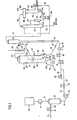
- the invention involves introducing a charge stock comprising slurried and/or at least partially dissolved coal and hydrocarbon oil feed into a progressive flow catalytic cracking zone, such as for example a riser cracking zone.
- a progressive flow catalytic cracking zone such as for example a riser cracking zone.
- the charge stock mixture in at least a partially vaporized and/or atomized condition is formed into a stream or a suspension providing a lineal velocity of at least about 25 feet per second, comprising the coal, oil and hydrocarbon cracking catalyst which is also introduced into the cracking zone.
- the invention employs a cracking catalyst bearing a sufficient accumulation of heavy metal deposits of at least about 1500 Nickel Equivalents which is brought in contact with the oil-coal mixture and, optionally, with a hydrogen donor material in a reaction zone under conditions whereby hydrogen is formed in the stream by dehydrogenation of the oil and/or hydrogen donor material charged.
- the hydrogen generated under the conditions of the progressive flow reaction zone provides hydrogen in the mixture for promoting the production of liquid products from coal.
- mobile hydrogen is formed under a combination of vapor conditions comprising vapor residence time in the catalytic cracking contact zone in the range of up to 10 seconds, when employing a temperature in the range of 482°C to 760°C and a total pressure of 0.69 to 3.45 bar. It is intended that the operating conditions selected are sufficient for causing a conversion of the oil to the extent of at least 50 volume percent per pass in the cracking zone.
- the resultant products of coal liquification, hydrogenation and cracking, as well as products of charged oil cracking are separated from the cracking catalyst following traverse of the cracking zone.
- coals of a rank lower than anthracite such as sub- anthracite, bituminous, sub-bituminous, lignite or brown coal and peat (which is included within the term "coal” as used herein), are preferred in that they generally tend to give somewhat higher yields of liquid products than anthracite.
- anthracite such as sub- anthracite, bituminous, sub-bituminous, lignite or brown coal and peat
- the coal may be introduced into the progressive flow cracking zone either in substantially undissolved, partly solid or fully dissolved form.
- the coal-oil mixture is introduced into the reaction zone in at least partly solid form within a period of ten minutes or less, preferably 5 minutes or less and still more preferably 1 minute or less, after initial contact between the coal and oil feed.
- the coal is supplied to the cracking zone in a form which includes substantial ash, and if the ash is to be recovered from the cracking catalyst by elutriation, then it is desirable to crush the coal to a particle size smaller than the fluidized catalyst employed in the cracking zone. For example, a coal particle size of about 200 mesh or smaller is preferred.
- the oil feed may be any petroleum hydrocarbon oil susceptible of at least 50 volume percent per pass conversion in a progressive flow catalytic cracking zone under the temperature, pressure and residence time conditions set forth herein.
- a naturally occurring hydrocarbon oil or other oil such as an oil which is the result of one or more refining operations as defined in U.S. Patents 4,081,351 to Heinemann and 4,108,758 to Schoennagel et al.
- hydrocarbon oils such as crude oil, crude oil fractions, shale oils and the like, do of course include certain non-hydrocarbon materials such as sulfur or its compounds, nitrogen compounds, heavy metal compounds and alkali or alkaline earth metal compounds, but such do not deprive the oils of their essentially hydrocarbon character. Moreover, it should be understood that such oils may be subjected to various pre-treatments as necessary to reduce the quantities of the above mentioned non- hydrocarbons materials present in the oil.
- the preferred hydrocarbon oils for practicing the invention are desalted crude, a 204°C+ fraction of desalted crude and conventional FCC gas oils characterized by relatively low carbon residues on pyrolysis (e.g. less than 1) and by relatively low contents of heavy metals.
- carbo- metallic oils characterized by a carbon residue on pyrolysis of at least 1 and a heavy metals content of at least 4, such carbo-metallic oils being described in greater detail below.
- non-hydrocarbon materials in crude oil are a number of components which can affect the operation of FCC processes. Certain of these, such as the lighter metals, can be economically removed by desalting operations, which are part of the normal procedure for pretreating crude oil for fluid catalytic cracking. Other materials, such as coke precursors, asphaltenes and the like, tend to break down into carbonaceous deposits during the cracking operation, which materials deposit on the catalyst, impairing contact between the hydrocarbon feedstock and the catalyst, and generally reducing its potency or activity level.
- the coke-forming tendency or coke precursor content of an oil can be ascertained by determining the weight percent of carbon remaining after a sample of that oil has been pyrolyzed.
- the industry accepts this value as a measure of the extent to which a given oil tends to form non-catalytic coke when employed as feedstock in a catalytic cracker.
- Two established tests are recognized, the Conradson Carbon and Ramsbottom Carbon tests, the former being described in ASTM D189-76 and the latter being described in ASTM Test No. D524-76.
- Conradson carbon values on the order of about 0.05 to about 1.0 are regarded as indicative of acceptable feed.
- a particular embodiment of the present invention is concerned with the use of hydrocarbon feedstocks which have higher Conradson carbon values and thus exhibit substantially greater potential for coke formation than the usual feeds.
- the term "heavy metals” refers to nickel, vanadium, copper and iron, although trace amounts of other heavy metal elements may sometimes be present.
- the heavy metal inventory of the feed transfers almost quantitatively from the feedstock oil to the catalyst particles.
- the heavy metals initially tend to deposit and agglomerate near the surface of a porous catalyst matrix, significant proportions of these metals migrate to the interior of the catalyst matrix where they can deposit a crystalline zeolite cracking component or other catalytic promoters carried within the matrix.
- the heavy metals content of an oil can be expressed by the following formula (patterned after that of W. L. Nelson in Oil and Gas Journa/, page 143, October 23, 1961) in which the content of each metal present is expressed in parts per million of such metal, as metal, on a weight basis, based on the weight of feed:
- the heavy metal content of feedstock for FCC processing is restricted to a relatively low level, e.g., about 0.25 ppm Nickel Equivalents or less.
- the present invention is concerned with the processing of feedstocks containing heavy metals promoting dehydrogenation which are in excess of this value and which have a significant potential for accumulating on and poisoning catalyst activity-selectivity characteristics under given operating conditions.
- the above formula can also be employed as a measure of the accumulation of heavy metals on cracking catalyst, except that the quantity of metal employed in the formula is based on the weight of catalyst (moisture free basis) instead of the weight of feed.
- the metal content of the catalyst is maintained at a level which may for example be in the range of about 200 to about 600 ppm Nickel Equivalents.
- the process of the present invention is concerned, however, with the use of catalyst compositions having a substantially larger content of deactivating metals, and which therefore has a much greater than normal tendency to promote dehydrogenation, aromatic condensation, gas production or coke formation. Such high metals accumulation is normally' regarded as quite undesirable in FCC processing.
- the invention may be practiced with any hydrocarbon cracking catalyst having the requisite heavy metals content and capable of producing at least a 50 volume percent per pass conversion of the charge stock in progressive flow catalytic cracking under the conditions set forth herein, and at a catalyst to oil weight ratio in the range of about 3 to about 18.
- Particularly preferred are those cracking catalysts conventionally used in fluid catalytic cracking, such as for instance the silica alumina cracking catalysts which can be used alone or in admixture with other catalysts.
- the most preferred catalysts are the crystalline alumino silicates prepared from either natural or synthetic zeolites, and especially those zeolite catalysts characterized by matrices with feeder pores having large minimum diameters and large mouths to facilitate diffusion of high molecular weight molecules through the matrix to the portal surface area of the molecular sieve particles within the matrix.
- Such catalysts are referred to in greater detail hereinafter.
- the heavy metals content of the catalyst tends to dehydrogenate components of the charge stock (including feed, products or both) and/or hydrogen donor materials (other than hydrogen itself) which have also been brought into contact with the catalyst.
- Illustrative hydrogen donors are water (which may be introduced into the reaction zone and/or to the feed upstream of the reaction zone) in the form of liquid water or steam, naphtha, tetralin, decalin, and/or gasiform donor materials contributing either non-molecular mobile hydrogen and/or carbon-hydrogen fragments (such as C 1 -C S materials and the low molecular weight fraction of crude petroleum).
- the relative quantities of coal and oil employed in this process can vary widely, it being necessary only that there be sufficient oil to render the resultant mixture of coal and oil readily pumpable and sufficiently uniform so as not to impair operation of the cracking unit, at least when preheated.
- weight ratios of oil to coal of at least about 1:1, more specifically at least about 3:1 and still more specifically at least about 5:1, are contemplated.
- the oil to coal ratio is preferably at least 7:1 and most preferably at least about 9:1.
- the oil to coal ratio will be in the range of up to about 1000:1, more typically up to about 100:1 and preferably. up to about 33:1.
- the invention may be practiced with a wide variety of oils. Some of these oils may be sufficiently low in their content of heavy metals so that they will not accumulate the requisite heavy metals on the catalyst when the cracking unit is operated at catalyst replacement rates typical of normal FCC operations. In such case the requisite heavy metals may be provided on the catalyst by any suitable means, such as by pre-impregnation of the catalyst prior to introduction into the cracking zone, or for example by injecting additives containing the heavy metals into the cracking zone.
- Nickel-Equivalents-containing oils in combination with crystalline zeolite containing cracking catalysts under selected cracking conditions as employed in the RCC process constitute beneficial conditions for carrying out the present invention.
- Such oil can supply and maintain the above-mentioned heavy metals content of at least about 1500 Nickel Equivalents in the cracking catalyst.
- carbo-metallic oils having the above-mentioned metals level in conjunction with a carbon residue of more than one, e.g. a carbo-metallic oil. Therefore, preferred and other embodiments of the carbo-metallic oils, zeolite cracking catalysts and RCC cracking conditions will now be described in greater detail.
- a carbo-metallic converter feed comprises or is composed of oil which boils above 343°C.
- oil or at least the 343°C+ portion thereof, is characterized by a heavy metal content of at least 4, preferably more than 5, and most preferably at least 5.5 ppm of Nickel Equivalents by weight and by a carbon residue on pyrolysis of at least 1 % and more preferably at least 2% by weight.
- the carbo-metallic feed in the form of a pumpable liquid, is brought into contact with hot conversion catalyst in a weight ratio of catalyst to feed in the range of 3 to 18 and preferably more than 6.
- the feed in said mixture undergoes a conversion step which includes cracking while the mixture of feed and catalyst is flowing through a progressive flow type reactor.
- the reactor includes an elongated reaction chamber which is at least partly vertical or inclined and in which the feed material, resultant products and catalyst are maintained in contact with one another while flowing as a dilute phase or stream for a predetermined riser residence time in the range of 0.5 to 10 seconds.
- the feed, catalyst, and other materials may be introduced into the reaction chamber at one or more points along its length.
- the reaction is conducted at a temperature of 482°Cto 760°C, measured at the reaction chamber exit, under a total pressure of 0.69 to 3.45 bar under conditions sufficiently severe to provide a conversion per pass in the range of 50% or more and to lay down coke on the catalyst in an amount in the range of 0.3 to 3% by weight of catalyst and preferably at least 0.5%.
- the overall rate of coke production, based on weight of fresh feed, is in the range of 4 to 14% by weight.
- the catalyst is separated from the products, is thereafter stripped to remove high boiling entrained hydrocarbon components and other entrained or adsorbed hydrocarbons and is then regenerated with an oxygen-containing combustion-supporting gas under conditions of time, temperature and atmosphere sufficient to reduce the carbon on the regenerated catalyst to about 0.25% or less and preferably about 0.05% or less by weight.
- the process may be operated without added molecular hydrogen in the reaction chamber. If desired, and preferably, the process may be operated without prior hydrotreating of the feed and/or without other process for removal of asphaltenes, porphyrins and metals from the feed, and this is true even where the carbo-metallic oil as a whole contains more than about 4, or more than about 5 or even more than about 5.5 ppm Nickel Equivalents by weight of heavy metal and has a carbon residue on pyrolysis greater than about 1%, greater than about 1.4% or greater than about 2% by weight. Moreover, all of the converter feed, as above described, may be cracked in one and the same conversion chamber.
- the cracking reaction may be carried out with a catalyst which has previously been used (recycled, except for such replacement as required to compensate for normal losses and deactivation) to crack a carbo- metallic oil-containing feed under the above described conditions.
- Heavy hydrocarbons not cracked to form gasoline in a first pass may be recycled with or without hydrotreating for further cracking in contact with the same kind of feed in which they originated and were first subjected to cracking conditions, and under the same kind of conditions. Operation in a substantially once-through or single pass mode (e.g. less than about 15% by volume of recycle based on volume of fresh feed) is preferred.
- the present invention provides a process for the continuous catalytic conversion of a wide variety of carbo-metallic oils to lower molecular weight products, while maximizing production of highly valuable liquid products, and making it possible, if desired, to avoid vacuum distillation and other expensive treatments such as hydrotreating.
- the invention is applicable to carbo-metallic oils, whether of petroleum origin or not. For example, provided they have the requisite boiling range, carbon residue on pyrolysis and heavy metals content, the invention may be applied to the processing of such widely diverse materials as heavy bottoms from crude oil, heavy bitumen crude oil, those crude oils known as "heavy crude” which approximate the properties of reduced crude, shale oil, tar sand extract, atmospheric and vacuum reduced crude, extracts and/ or bottoms (raffinate) from solvent deasphalting, aromatic extract from lube oil refining, tar bottoms, heavy cycle oil, slop oil, other refinery waste streams and mixtures of the foregoing.
- Such mixtures can for instance be prepared by mixing available hydrocarbon fractions, including oils, tars, pitches and the like.
- Persons skilled in the art are aware of techniques for demetalation of carbo-metallic oils, and demetalated oils may be converted using the invention; but it is an advantage of the invention that it can employ as feedstock carbo-metallic oils that have had no prior demetalation treatment.
- the invention can be applied to hydrotreated feedstocks; but it is an advantage of the invention that it can successfully convert carbo-metallic oils which have had substantially no prior hydrotreatment.
- the preferred application of the process is to residual oils and reduced crude, i.e., that portion or fraction of crude oil boiling at and above 343°C, alone or in admixture with vacuum gas oils or FCC tower bottoms. While the use of material that has been subjected to vacuum distillation is contemplated, it is an advantage of the invention that it can satisfactorily process material which has had no prior vacuum distillation, thus saving on capital investment and operating costs as compared to conventional FCC processes that require a vacuum distillation unit.
- one provides a carbo-metallic oil feedstock, at least 70%, more preferably at least 85% and still more preferably 100% (by volume) of which boils at and above 343°C. All boiling temperatures herein are based on standard atmospheric pressure conditions.
- carbo-metallic oil partly or wholly composed of material which boils at and above 343°C, such material is referred to herein as 343°C+ material; and 343°C+ material which is part of or has been separated from an oil containing component boiling above and below 343°C may be referred to as a 343°C+ fraction.
- the terms "boils above” and "343°C+” are not intended to imply that all of the material characterized by said terms will have the capability of boiling.
- the carbo-metallic oils contemplated by the invention may contain material which may not boil under any conditions; for example, certain asphalts and asphaltenes may crack thermally during distillation, apparently without boiling.
- the feed comprises at least 70% by volume of material which boils above 343°C, it should be understood that the 70% in question may include some material which will not boil or volatilize at any temperature.
- These non-boilable materials when present may frequently or for the most part be concentrated in portions of the feed which do not boil below 538°C, 552°C or higher.
- the contemplated feeds, or at least the 343°C+ material therein have a carbon residue on pyrolysis of at least about 2 or greater.
- the Conradson carbon content may be in the range of about 2 to about 12 and most frequently at least about 4. A particularly common range is about 4 to about 8. Those feeds having a Conradson carbon content greater than about 6 may need special means for controlling excess heat in the regenerator.
- the feed has an average composition characterized by an atomic hydrogen to carbon ratio in the range of about 1.2 to about 1.9, and preferably about 1.3 to about 1.8.
- the carbo-metallic feeds employed in accordance with the invention, or at least the 650°F+ material therein, may contain at least 4 parts per million of Nickel Equivalents, as defined above, of which at least 2 parts per million is nickel (as metal, by weight).
- Carbo-metallic oils within the above range can be prepared from mixtures of two or more oils, some of which do and some of which do not contain the quantities of Nickel Equivalents and nickel set forth above. It should also be noted that the above values for Nickel Equivalents and nickel represent time-weighted averages for a substantial period of operation of the conversion unit, such as one month, for example.
- the carbo-metallic oils useful in the invention may and usually do contain significant quantities of heavy, high boiling compounds containing nitrogen, a substantial portion of which may be basic nitrogen.
- the total nitrogen content of the carbo-metallic oils may be at least 0.05% by weight. Since cracking catalysts owe their cracking activity to acid sites on the catalyst surface or in its pores, basic nitrogen-containing compounds may temporarily neutralize these sites, poisoning the catalyst. However, the catalyst is not permanently damaged since the nitrogen can be burned off the catalyst during regeneration, as a result of which the acidity of the active sites is restored.
- the carbo-metallic oils may also include significant quantities of pentane insolubles, for example, at least about 0.5% by weight, and more typically 2% or more or even about 4% or more. These may include for instance asphaltenes and other materials.
- Alkali and alkaline earth metals generally do not tend to vaporize in large quantities under the distillation conditions employed in distilling crude oil to prepare the vacuum gas oils normally used as FCC feedstocks. Rather, these metals remain for the most part in the "bottoms" fraction (the non-vaporized high boiling portion) which may for instance be used in the production of asphalt or other by-products.
- bottoms the non-vaporized high boiling portion
- reduced crude and other carbo-metallic oils are in many cases bottoms products, and therefore may contain significant quantities of alkali and alkaline earth metals such as sodium. These metals deposit upon the catalyst during cracking.
- these metals may undergo interactions and reactions with the catalyst (including the catalyst support) which are not normally experienced in processing VGO under conventional FCC processing conditions. If the catalyst characteristics and regeneration conditions so require, one will of course take the necessary precautions to limit the amounts of alkali and alkaline earth metal in the feed, which metals may enter the feed not only as brine associated with the crude oil in its natural state, but also as components of water or steam which are supplied to the cracking unit. Thus, careful desalting of the crude used to prepare the carbo-metallic feed may be important when the catalyst is particularly susceptible to alkali and alkaline earth metals.
- the content of such metals (hereinafter collectively referred to as "sodium") in the feed can be maintained at about 1 ppm or less, based on the weight of the feedstock.
- the sodium level of the feed may be keyed to that of the catalyst, so as to maintain the sodium level of the catalyst which is in use substantially the same as or less than that of the replacement catalyst which is charge to the unit.
- the carbo-metallic oil feedstock constitutes at least 70% by volume of material which boils above 343°C, and at least 10% of the material which boils above 343°C, will not boil below 552°C.
- the average composition of this 343°C+ material may be further characterized by: (a) an atomic hydrogen to carbon ratio in the range of 1.3 to 1.8; (b) a Conradson carbon value of at least 2; (c) at least four parts per million of Nickel Equivalents, as defined above, of which at least two parts per million is nickel (as metal, by weight); and (d) at least one of the following: (i) at least 0.3% by weight of sulfur, (ii) at least 0.05% by weight of nitrogen, and (iii) and other components found in oils of petroleum and non- petroleum origin may also be present in varying quantities providing they do not prevent operation of the process.
- the present invention has the definite advantage that it can successfully produce large conversions and very substantial yields of liquid hydrocarbon fuels from carbo-metallic oils which have not been subjected to any substantial amount of cracking.
- at least 85%, more preferably at least 90% and most preferably substantially all of the carbo-metallic feed introduced into the present process is oil which has not previously been contacted with cracking catalyst under cracking conditions.
- the process of the invention is suitable for operation in a substantially once-through or single pass mode.
- the volume of recycle, if any, based on the volume of fresh feed is preferably 15% or less and more preferably 10% or less.
- the weight ratio of catalyst to fresh . feed (feed which has not previously been exposed to cracking catalyst under cracking conditions) used in the process is in the range of 3 to 18.
- Preferred and more preferred ratios are 4 to 12, more preferably 5 to 10 and still more preferably 6 to 10, a ratio of 10 presently being considered most nearly optimum.
- controlling the catalyst to oil ratio at relatively low levels within the aforesaid ranges tends to reduce the coke yield of the process, based on fresh feed.
- daily plant through-put is defined as the number of barrels of fresh feed boiling above 343°C which that plant processes per average day of operation to liquid products boiling below 221°C (430°F).
- the present invention may be practiced in the range of 11.4 to 30 grams of catalyst inventory per liter of daily plant through-put. Based on the objective of maximizing contact of feed with fresh catalyst, it has been suggested that operating with 11.4 to 28.5 or even less than 11.4 grams of catalyst inventory per liter of daily plant through-put is desirable when operating with carbo- metallic oils.
- 11.4 to 28.5 or even less than 11.4 grams of catalyst inventory per liter of daily plant through-put is desirable when operating with carbo- metallic oils.
- one may be able, at a given rate of catalyst replacement, to reduce effective metals levels on the catalyst by operating with a higher inventory, say in the range of 68.5 to 114 grams per liter of daily through-put capacity.
- catalyst may be added continuously or periodically, such as, for example, to make up for normal losses of catalyst from the system.
- catalyst addition may be conducted in conjunction with withdrawal of catalyst, such as, for example, to maintain or increase the average activity level of the catalyst in the unit.
- the rate at which virgin catalyst is added to the unit may be in the range of 0.3 to 8.6, more preferably 0.43 to 5.7, and most preferably to 0.57 to 4.3 grams per liter of feed. If on the other hand equilibrium catalyst from FCC operation is to be utilized, replacement rates as high as 4.3 grams per liter can be practiced.
- the process may be practiced with catalyst bearing accumulations of heavy metal(s) in the form of elemental metal(s), oxide(s), sulfide(s) or other compounds which heretofore would have been considered quite intolerable in conventional FCC-VGO operations.
- catalyst bearing heavy metals accumulations in the range of about 3,000 or more ppm Nickel Equivalents, on the average, is contemplated.
- the concentration of Nickel Equivalents of metals on catalyst can range up to about 50,000 ppm or higher. More specifically, the accumulation may be in the range of about 3,000 to about 30,000 ppm, preferably in the range of 3,000 to 20,000 ppm, and more preferably about 3,000 to about 12,000 ppm.
- these very poor grades of oil are processed in a carbo-metallic process, they may lead to uneconomical operations because of high heat loads on the regenerator and/or high catalyst addition rates to maintain adequate catalyst activity and/or selectivity.
- these oils may be pretreated with a sorbent to reduce the levels of these contaminants to the aforementioned or lower values.
- Such upgrading processes are described in U.S. Patent No. 4,263,128 of April 21, 1981, in the name of David B. Bartholic.
- the equilibrium concentration of heavy metals in the circulating inventory of catalyst can be controlled (including maintained or varied as desired or needed) by manipulation of the rate of catalyst addition discussed above.
- addition of catalyst may be maintained at a rate which will control the heavy metals accumulation on the catalyst in one of the ranges set forth above.
- a catalyst having a relatively high level of cracking activity providing high levels of conversion and productivity at low residence times.
- the conversion capabilities of the catalyst may be expressed in terms of the conversion produced during actual operation of the process and/or in terms of conversion produced in standard catalyst activity tests.
- catalyst which, in the course of extended operation under prevailing process conditions, is sufficiently active for sustaining a level of conversion of at least 50% and more preferably at least 60%.
- conversion is expressed in liquid volume percent, based on fresh feed.
- the preferred catalyst may be defined as one which, in its virgin or equilibrium state, exhibits a specified activity expressed as a percentage in terms of MAT (micro-activity test) conversion.
- the foregoing percentage is the volume percentage of standard feedstock which a catalyst under evaluation will convert to 221°C end point gasoline, lighter products and coke at 482°C, 16 WHSV (weight hourly space velocity, calculated on a moisture free basis, using clean catalyst which has been dried at 593°C, weighed and then conditioned, for a period of at least 8 hours at 25°C and 50% relative humidity, until about one hour or less prior to contacting the feed) and 3C/O (catalyst to oil weight ratio) by ASTM D-32 MAT test D-3907-80, using an appropriate standard feedstock, e.g. a sweet light primary gas oil, such as that used by Davison, Divisions of W. R.
- a sweet light primary gas oil such as that used by Davison, Divisions of W. R.
- the gasoline end point and boiling temperature- volume percent relationships of the product produced in the MAT conversion test may for example be determined by simulated distillation techniques, for example modifications of gas chromate graphic "Sim-D", ASTM D-2887-73. The results of such simulations are in reasonable agreement with the results obtained by subjecting larger samples of material to standard laboratory distillation techniques. Conversion is calculated by subtracting from 100 the volume percent (based on fresh feed) of those products heavier than gasoline which remain in the recovered product.
- relative activity is a ratio obtained by dividing the weight of a standard or reference catalyst which is or would be required to produce a given level of conversion, as compared to the weight of an operating catalyst (whether proposed or actually used) which is or would be required to produce the same level of conversion in the same or equivalent feedstock under the same or equivalent conditions.
- Said ratio of catalyst weights may be expressed as a numerical ratio, but preferably is converted to a percentage basis.
- the standard catalyst is preferably chosen from among catalysts useful for conducting the present invention, such as for example zeolite fluid cracking catalysts, and is chosen for its ability to produce a predetermined level of conversion in a standard feed under the conditions of temperature, WHSV, catalyst to oil ratio and other conditions set forth in the preceding description of the MAT conversion test and in ASTM D-32 MAT test D-3907-80. Conversion is the volume percentage of feedstock that is converted to 221°C end point gasoline, lighter products and coke. For standard feed, one may employ the above-mentioned light primary gas oil, or equivalent.
- a "standard catalyst curve" a chart or graph of conversion (as above defined) vs. reciprocal WHSV for the standard catalyst and feedstock.
- a sufficient number of runs is made under ASTM D-3907-80 conditions (as modified above) using standard feedstock at varying levels of WHSV to prepare an accurate "curve" of conversion vs. WHSV for the standard feedstock.
- This curve should traverse all or substantially all of the various levels of conversion including the range of conversion within which it is expected that the operating catalyst will be tested. From this curve, one may establish a standard WHSV for test comparisons and a standard value of reciprocal WHSV corresponding to that level of conversion which has been chosen to represent 100% relative activity in the standard catalyst.
- the aforementioned reciprocal WHSV and level of conversion are, respectively, 0.0625 and 75%.
- the relative activity may then be calculated by dividing the hypothetical reciprocal WHSV by the reciprocal standard WHSV, which is 1/16, or .0625.
- the result is relative activity expressed in terms of a decimal fraction, which may then be multiplied by 100 to convert to percent relative activity.
- a relative activity of 0.5, or 50% means that it would take twice the amount of the operating catalyst to give the same conversion as the standard catalyst, i.e., the production catalyst is 50% as active as the reference catalyst.
- the catalyst may be introduced into the process in its virgin form or, as previously indicated, in other than virgin form; e.g. one may use equilibrium catalyst withdrawn from another unit, such as catalyst that has been employed in the cracking of a different feed.
- equilibrium catalyst withdrawn from another unit such as catalyst that has been employed in the cracking of a different feed.
- the preferred catalysts may be described on the basis of their activity "as introduced” into the process of the present invention, or on the basis of their "as withdrawn” or equilibrium activity in the process of the present invention, or on both of these bases.
- a preferred activity level of virgin and non-virgin catalyst "as introduced” into the process of the present invention is at least about 60% by MAT conversion, and preferably at least about 20%, more preferably at least about 40% and still more preferably at least about 60% in terms of relative activity.
- An acceptable "as withdrawn” or equilibrium activity level of catalyst which has been used in the process of the present invention is at least about 20% or more, but about 40% or more and preferably about 60% or more are preferred values on a relative activity basis, and an activity level of 60% or more on a MAT conversion basis is also contemplated. More preferably, it is desired to employ a catalyst which will, under the conditions of use in the unit, establish an equilibrium activity at or above the indicated level. The catalyst activities are determined with catalyst having less than 0.01 coke, e.g. regenerated catalyst.
- a particularly preferred class of catalysts includes those which have pore structures into which molecules of feed material may enter for adsorption and/or for contact with active catalytic sites within or adjacent the pores.
- Various types of catalysts are available within this classification, including for example the layered silicates, e.g., smectites. Although the most widely available catalysts within this classification are the well-known zeolite-containing catalysts, non-zeolite catalysts are also contemplated.
- the preferred zeolite-containing catalysts may include any zeolite, whether natural, semisynthetic or synthetic, alone or in admixture with other materials which do not significantly impair the suitability of the catalyst, provided the resultant catalyst has the activity and pore structure referred to above.
- the virgin catalyst may include the zeolite component associated with or dispersed in a porous refractory inorganic oxide carrier, in such case the catalyst may for example contain about 1% to about 60%, more preferably about 15 to about 50%, and most typically about 20 to about 45% by weight, based on the total weight of catalyst (water free basis) of the zeolite, the balance of the catalyst being the porous refractory inorganic oxide alone or in combination with any of the known adjuvants for promoting or suppressing various desired and undesired reactions.
- the zeolite components of the zeolite-containing catalysts will be those which are known to be useful in FCC cracking processes.
- these are crystalline aluminosilicates, typically made up of tetra coordinated aluminum atoms associated through oxygen atoms with adjacent silicon atoms in the crystal structure.
- the term "zeolite" as used in this disclosure contemplates not only aluminosilicates, but also substances in which the aluminum has been partly or wholly replaced, such as for instance by gallium and/or other metal atoms, and further includes substances in which all or part of the silicon has been replaced, such as for instance by germanium. Titanium and zirconium substitution may also be practiced.
- the zeolite may be ion exchanged, and where the zeolite is a component of a catalyst composition, such ion exchanging may occur before or after incorporation of the zeolite as a component of the composition.
- Suitable cations for replacement of sodium in the zeolite crystal structure include ammonium (decomposable to hydrogen), hydrogen, rare earth metals, alkaline earth metals etc.
- Various suitable ion exchange procedures and cations which may be exchanged into the zeolite crystal structures are well known to those skilled in the art.
- Examples of the naturally occurring crystalline alumino-silicate zeolites which may be used as or included in the catalyst for the present invention are faujasite, mordenite, clinoptilote, chabazite, analcite, crionite, as well as levynite, dachiardite, paulingite, noselite, ferriorite, heulandite, scolccite, stibite, harmotome, phillipsite, brewsterite, flarite, datolite, gmelinite, caumnite, leucite, lazurite, scaplite, mesolite, ptolite, nephline, matrolite, offretite and sodalite.
- Examples of the synthetic crystalline alumino- silicate zeolites which are useful as or in the catalyst for carrying out the present invention are Zeolite X, U.S. Patent No. 2,882,244; Zeolite Y, U.S. Patent No. 3,130,007; and Zeolite A, U.S. Patent No. 2,882,243; as well as Zeolite B, U.S. Patent No. 3,008,803; Zeolite D, Canada Patent No. 661,981; Zeolite E, Canada Patent No. 614,495; Zeolite F, U.S. Patent No. 2,996,358; Zeolite H, U.S. Patent No. 3,010,789; Zeolite J. U.S. Patent No.
- the crystalline aluminosilicate zeolites having a faujasite-type crystal structure are particularly preferred for use in the present invention. This includes particularly natural faujasite and Zeolite X and Zeolite Y.
- the crystalline aluminosilicate zeolites such as synthetic faujasite, will under normal conditions crystallize as regularly shaped, discrete particles of about one to about ten microns in size, and, accordingly, this is the size range frequently found in commercial catalysts which can be used in the invention.
- the particle size of the zeolites is from about 0.1 to about 10 microns and more preferably is from about 0.1 to about 2 microns or less.
- zeolites prepared in situ from calcined kaolin may be characterized by even smaller crystallites. Crystalline zeolites exhibit both an interior and an exterior surface area, the latter being defined as "portal" surface area, with the largest portion of the total surface area being internal.
- portal surface area we refer to the outer surface of the zeolite crystal through which reactants are considered to pass in order to convert to lower boiling products.
- Blockages of the internal channels by, for example, coke formation, blockages of entrance to the internal channels by deposition of coke in the portal surface area, and contamination by metals poisoning, will greatly reduce the total zeolite surface area. Therefore, to minimize the effect of contamination and pore blockage, crystals larger than the normal size cited above are preferably not used in the catalysts of this invention.
- zeolite-containing catalysts are available with carriers containing a variety of metal oxides and combination thereof, include for example silica, alumina, magnesia, and mixtures thereof and mixtures of such oxides with clays as e.g. described in U.S. Patent No. 3,034,948.
- One may for example select any of the zeolite-containing molecular sieve fluid cracking catalysts which are suitable for production of gasoline from vacuum gas oils.
- certain advantages may be attained by judicious selection of catalysts having marked resistance to metals.
- a metal resistant zeolite catalyst is, for instance, described in U.S. Patent No.
- the catalyst contains 1-40 weight percent of a rare earth- exchanged zeolite, the balance being a refractory metal oxide having specified pore volume and size distribution.
- Other catalysts described as "metals-tolerant" are described in the above mentioned Cimbalo, et al article.
- a useful catalyst may have a skeletal density of 2400 grams per liter and an average particle size of 60-70 microns, with less than 10% of the particles having a size less than 40 microns and less than 80% having a size less than 50-60 microns.
- the AGZ-290, GRZ-1, CCZ-220 and Super DX catalysts referred to above are products of W. R. Grace and Co.
- F-87 and FOX-90 are products of Filtrol, while HFZ-20 and HEZ-55 are products of Engelhard/Houdry.
- the above are properties of virgin catalyst and, except in the case of zeolite content, are adjusted to a water free basis, i.e., based on material ignited at 954°C.
- the zeolite content is derived by comparison of the x-ray intensities of a catalyst sample and of a standard material composed of high purity sodium Y zeolite in accordance with draft #6, dated January 9, 1978, of proposed ASTM Standard Method entitled "Determination of the Faujasite Content of a Catalyst".
- the Super D family and especially a catalyst designated GRZ-1 are particularly preferred.
- Super DX has given particularly good results with Arabian light crude.
- the GRZ-1 although substantially more expensive than the Super DX at present, appears somewhat more metals-tolerant.
- the best catalysts for carrying out the present invention are those which are characterized by matrices with feeder pores having a large minimum diameter and large mouths to facilitate diffusion of high molecular weight molecules through the matrix to the portal surface area of molecular sieve particles within the matrix.
- Such matrices preferably also have a relatively large pore volume in order to soak up unvaporized portions of the carbo-metallic oil feed.
- significant numbers of liquid hydrocarbon molecules can diffuse to active catalytic sites both in the matrix and in sieve particles on. the surface of the matrix.
- catalysts having a total pore volume greater than 0.2 ml/gm, preferably at least 0.4 ml/gm, more preferably at least 0.6 ml/gm and most preferably in the range of 0.7 to 1.0 cc/gm, and with matrices wherein at least 0.1 cc/gm, and preferably at least 0.2 cc/gm of said total pore volume is comprised of feeder pores having diameters in the range of about 400 to about 6000 angstrom units, more preferably in the range of about 1000 to about 6000 angstrom units.
- Catalysts for carrying out the present invention may also employ other metal additives for controlling the adverse effects of vanadium as described in PCT International Application Serial No. PCT/US81/00356 filed in the U.S. Receiving Office on March 19,1981, in the names of Ashland Oil, Inc., et al., and entitled "Immobilization of Vanadia Deposited on Catalytic Materials During Carbo-Metallic Oil Conversion".
- PCT International Application Serial No. PCT/US81/00356 filed in the U.S. Receiving Office on March 19,1981, in the names of Ashland Oil, Inc., et al., and entitled "Immobilization of Vanadia Deposited on Catalytic Materials During Carbo-Metallic Oil Conversion".
- the manner in which these other metal additives are believed to interact with vanadium is set forth in said PCT international application, the entire disclosure of which is incorporated herein by reference.
- the passivating mechanism of titanium and zirconium on nickel, iron and copper is believed to be similar to that of aluminum and silicon, namely, an oxide and/or spinel coating may be formed.
- the additive is introduced directly into the conversion process, that is into the riser into the regenerator or into any intermediate components, the additive is preferably an organo-metallic compound of titanium or zirconium soluble in the hydrocarbon feed or in a hydrocarbon solvent miscible with the feed.
- organo-metallic compounds of these metals are tetraisopropyltitanate, TI (C 3 H 7 0) 4 , available as Tyzor from the Du Pont Company; zirconium isopropoxide, Zr (C 3 H 7 0) 4 ; and zirconium 2,4-pentanedionate-Zr (C 5 H 7 0 2 ) 4 .
- TI C 3 H 7 0
- Zr C 3 H 7 0 4
- zirconium 2,4-pentanedionate-Zr C 5 H 7 0 2 ) 4 .
- organo-metallics are only a partial example of the various types available and others would include alcoholates, esters, phenolates, naphthenates, carboxylates, dienyl sandwich compounds, and the like.
- titanium tetrachloride zirconium tetrachloride and zirconium acetate
- water soluble inorganic salts of these metals including the sulfates, nitrates and chlorides, which are relatively inexpensive.
- a 1:1 atomic ratio is equivalent to about a 1.0 weight ratio of titanium to nickel plus vanadium, and to about a 2.0 weight ratio of zirconium to nickel plus vanadium.
- Multiples of the 1:1 atomic ratio require the same multiple of the weight ratio.
- a 2:1 atomic ratio requires about a 2.0 titanium weight ratio and about a 4.0 zirconium weight ratio.
- Additives may be introduced into the riser, the regenerator or other conversion system components to passivate the non-selective catalytic activity of heavy metals deposited on the conversion catalyst.
- a particularly preferred catalyst also includes vanadium traps. It is also preferred to control the valence state of vanadium accumulations on the catalyst during regeneration.
- the process of the present invention can be conducted in the substantial absence of tin and/or antimony or at least in the presence of a catalyst which is substantially free of either or both of these metals.
- the process of the present invention may be operated with the above described carbo-metallic oil and catalyst as substantially the sole materials charged to the reaction zone, although charging of additional materials is not excluded.
- the charging of recycled oil to the reaction zone has already been mentioned.
- still other materials fulfilling a variety of functions may also be charged.
- the carbo-metallic oil and catalyst usually represent the major proportion by weight of the total of all materials charged to the reaction zone.
- Certain of the additional materials which may be used perform functions which offer significant advantages over the process as performed with only the carbo-metallic oil and catalyst. Among these functions are: controlling the effects of heavy metals and other catalyst contaminants; enhancing catalyst activity; absorbing excess heat in the catalyst as received from the regenerator; disposal of pollutants or conversion thereof to a form or forms in which they may be more readily separated from products and/or disposed of; controlling catalyst temperature; diluting the carbo-metallic oil vapors to reduce their partial pressure and increase the yield of desired products; adjusting feed/catalyst contact time; donation of hydrogen to a hydrogen deficient carbo-metallic oil feedstock; assisting in the dispersion of the feed; and possibly also distillation of products.
- Certain of the metals in the heavy metals accumulation on the catalyst are more active in promoting undesired reactions when they are in the form of elemental metal, than they are when in the oxidized form produced by contact with oxygen in the catalyst regenerator.
- the time of contact between catalyst and vapors of feed and product in past conventional catalytic cracking was sufficient so that hydrogen released in the cracking reaction was able to reconvert a significant portion of the less harmful oxides back to the more harmful elemental heavy metals.
- One can take advantage of this situation through the introduction of additional materials which are in gaseous (including vaporous) form in the reaction zone in admixture with the catalyst and vapors of feed and products.
- Added materials may be introduced into the process in any suitable fashion, some examples of which follow. For instance, they may be admixed with the carbo-metallic oil feedstock prior to contact of the latter with the catalyst. Alternatively, the added materials may, if desired, be admixed with the catalyst prior to contact of the latter with the feedstock. Separate portions of the added materials may be separately admixed with both catalyst and carbo-metallic oil. Moreover, the feedstock, catalyst and additional materials may, if desired, be brought together substantially simultaneously. A portion of the added materials may be mixed with catalyst and/or carbo-metallic oil in any of the above described ways, while additional portions are subsequently brought into admixture.
- a portion of the added materials may be added to the carbo-metallic oil and/or to the catalyst before they reach the reaction zone, while another portion of the added materials is introduced directly into the reaction zone.
- the added materials may be introduced at a plurality of spaced locations in the reaction zone or along the length thereof, if elongated.
- the amount of additional materials which may be present in the feed catalyst or reaction zone for carrying out the above functions, and others, may be varied as desired; but said amount will preferably be sufficient to substantially heat balance the process.
- These materials may for example be introduced into the reaction zone in a weight ratio relative to feed of up to about 0.4, preferably in the range of about 0.02 to about 0.4, more preferably about 0.03 to about 0.3 and most preferably about 0.05 to about 0.25.
- H 2 0 may be attained by introducing H 2 0 to the reaction zone in the form of steam or of liquid water or a combination thereof in a weight ratio relative to feed in the range of about 0.04 or more, or more preferably about 0.05 to about 0.1 or more.
- H 2 0 tends to inhibit reduction of catalyst-borne oxides, sulfites and sulfides to the free metallic form which is believed to promote condensation-dehydrogenation with consequent promotion of coke and hydrogen yield and accompanying loss of product.
- H 2 0 may also, to some extent, reduce deposition of metals onto the catalyst surface.
- H 2 0 tends to increase the acidity of the catalyst by Bronsted acid formation which in turn enhances the activity of the catalyst. Assuming the H 2 0 as supplied is cooler than the regenerated catalyst and/or the temperature of the reaction zone, the sensible heat involved in raising the temperature of the H 2 0 upon contacting the catalyst in the reaction zone or elsewhere can absorb excess heat from the catalyst. Where the H 2 0 is or includes recycled water that contains for example about 500 to about 5000 ppm of H 2 S dissolved therein, a number of additional advantages may accrue.
- H 2 S need not be vented to the atmosphere, the recycled water does not require further treatment to remove H 2 S and the H 2S may be of assistance in reducing coking of the catalyst by passivation of the heavy metals, i.e. by conversion thereof to the sulfide form which has a lesser tendency than the free metals to enhance coke and hydrogen production.
- the presence of H 2 0 can dilute the carbo-metallic oil vapors, thus reducing their partial pressure and tending to increase the yield of the desired products. It has been reported that H 2 0 is useful in combination with other materials in generating hydrogen during cracking; thus it may be able to act as a hydrogen donor for hydrogen deficient carbo-metallic oil feedstocks.
- the H 2 0 may also serve certain purely mechanical functions such as: assisting in the atomizing or dispersion of the feed; competing with high molecular weight molecules for adsorption on the surface of the catalyst, thus interrupting coke formation; steam distillation of vaporizable product from unvaporized feed material; and disengagement of product from catalyst upon conclusion of the cracking reaction. It is particularly preferred to bring together H 2 0, catalyst and carbometallic oil substantially simultaneously. For example, one may admix H 2 0 and feedstock in an atomizing nozzle and immediately direct the resultant spray into contact with the catalyst at the downstream end of the reaction zone.
- liquid water be brought into intimate admixture with the carbo-metallic oil in a weight ratio of about 0.04 to about 0.25 at or prior to the time of introduction of the oil into the reaction zone, whereby the water (e.g., in the form of liquid water or in the form of steam produced by vaporization of liquid water in contact with the oil) enters the reaction zone as part of the flow of feedstock which enters such zone.
- the foregoing is advantageous in promoting dispersion of the feedstock.
- the heat of vaporization of the water which heat is absorbed from the catalyst, from the feedstock, or from both, causes the water to be a more efficient heat sink than steam alone.
- the weight ratio of liquid water to feed is about 0.04 to about 0.2 more preferably about 0.05 to about 0.15.
- the liquid water may be introduced into the process in the above described manner or in other ways and in either event the introduction of liquid water may be accompanied by the introduction of additional amounts of water as steam into the same or different portions of the reaction zone or into the catalyst and/or feedstock.
- the amount of additional steam may be in a weight ratio relative to feed in the range of about 0.01 to about 0.25, with the weight ratio of total H 2 0 (as steam and liquid water) to feedstock being about 0.3 or less.
- the charging weight ratio of liquid water relative to steam in such combined use of liquid water and steam may for example range from about 15 which is presently preferred, to about 0.2. Such ratio may be maintained at a predetermined level within such range or varied as necessary or desired to adjust or maintain heat balance.
- the dehydrogenation-condensation activity of heavy metals may be inhibited by introducing hydrogen sulfide gas into the reaction zone.
- Hydrogen may be made available for hydrogen deficient carbo- metallic oil feedstocks by introducing into the reaction zone either a conventional hydrogen donor diluent such as heavy naphtha or relatively low molecular weight carbon-hydrocarbon fragment contributors, including for example: light paraffins; low molecular weight alcohols and other compounds which permit or favor intermolecular hydrogen transfer; and compounds that chemically combine to generate hydrogen in the reaction zone such as by reaction of carbon monoxide with water, or with alcohols, or with olefins, or with other materials or mixtures of the foregoing.
- a conventional hydrogen donor diluent such as heavy naphtha or relatively low molecular weight carbon-hydrocarbon fragment contributors, including for example: light paraffins; low molecular weight alcohols and other compounds which permit or favor intermolecular hydrogen transfer; and compounds that chemically combine to generate hydrogen in the
- the invention may be practiced in a wide variety of apparatus.
- the preferred apparatus includes means for rapidly vaporizing as much feed as possible and efficiently admixing feed and catalyst (although not necessarily in that order), for causing the resultant mixture to flow as a dilute suspension in a progressive flow mode, and for separating the catalyst from cracked products and any uncracked or only partially cracked feed at the end of a predetermined residence time or times, it being preferred that all or at least a substantial portion of the product should be abruptly separated from at least a portion of the catalyst.
- the apparatus may include, along its elongated reaction chamber, one or more points for introduction of carbo-metallic feed, one or more points for introduction of catalyst, one or more points for introduction of additional material, one or more points for withdrawal of products and one or more points for withdrawal of catalyst.
- the means for introducing feed, catalyst and other material may range from open pipes to sophisticated jets or spray nozzles, it being preferred to use means capable of breaking up the liquid feed into fine droplets.
- the liquid water and carbo-metallic oil, prior to their introduction into the riser are caused to pass through a propeller, apertured disc, or any appropriate high shear agitating means for forming a "homogenized mixture" containing finely divided droplets of oil and/or water with oil and/or water present as a continuous phase.
- the reaction chamber or at least the major portion thereof, be more nearly vertical than horizontal and have a length to diameter ratio of at least about 10, more preferably about 20 or 25 or more.
- a vertical riser type reactor is preferred. If tubular, the reactor can be of uniform diameter throughout or may be provided with a continuous or step-wise increase in diameter along the reaction path to maintain or vary the velocity along the flow path.
- the charging means (for catalyst and feed) and the reactor configuration are such as to provide a relatively high velocity of flow and dilute suspension of catalyst.
- the vapor or catalyst velocity in the riser will be usually at least 7.62 and more typically at least 10.7 meters per second. This velocity may range up to 16.8 or 22.9 meters or 30.5 meters of the reactor may be higher than that at the bottom and may for example be 24.4 meters per second at the top and 12.2 meters per second at the bottom.
- the velocity capabilities of the reactor will in general be sufficient to prevent substantial buildup of catalyst bed in the bottom or other portions of the riser, whereby the catalyst loading in the riser can be maintained below 64 or 80 grams, as for example 8 grams, and below 32 grams, as for example 13 grams, per liter, respectively, at the upstream (e.g., bottom) and downstream (e.g., top) ends of the riser.
- the progressive flow mode involves, for example, flowing of catalyst, feed and products as a stream in a positively controlled and maintained direction established by the elongated nature of the reaction zone. This is not to suggest however that there must be strictly linear flow. As is well known, turbulent flow and "slippage" of catalyst may occur to some extent especially in certain ranges of vapor velocity and some catalyst loadings, although it has been reported advisable to employ sufficiently low catalyst loadings to restrict slippage and back-mixing.
- the reactor is one which abruptly separates a substantial portion or all of the vaporized cracked products from the catalyst at one or more points along the riser, and preferably separates substantially all of the vaporized cracked products from the catalyst at the downstream end of the riser.
- a preferred type of reactor embodies ballistic separation of the catalyst and products; that is, catalyst is projected in a direction established by the riser tube, and is caused to continue its motion in the general direction so established, while the products, having lesser momentum, are caused to make an abrupt change of direction, resulting in an abrupt, substantially instantaneous separation of product from catalyst.
- the riser tube is provided with a substantially unobstructed discharge opening at its downstream end for discharge of catalyst.
- An exit port near the tube outlet adjacent the downstream end receives the products.
- the discharge opening communicates with a catalyst flow path which extends to the usual stripper and regenerator, while the exit port communicates with a product flow path which is substantially or entirely separated from the catalyst flow path and leads to separation means for separating the products from the relatively small portion of catalyst, if any, which manages to gain entry to the product exit port.
- the mode of catalyst/ product separation presently deemed best for practicing the present invention is disclosed in Figure 2, discussed below.
- the feedstock is customarily preheated, often to temperatures significantly higher than are required to make the feed sufficiently fluid for pumping and for introduction into the reactor. For example, preheat temperatures as high as 371°C or 427°C have been reported. But in our process as presently practiced it is preferred to restrict preheating of the feed, so that the feed is capable of absorbing a larger amount of heat from the catalyst while the catalyst raises the feed to conversion temperature, at the same time minimizing utilization of external fuels to heat the feedstock.
- the feedstock may be fed at ambient temperature.
- Heavier stocks may be fed at preheat temperatures of up to 316°C, typically 93°C to 260°C, but higher preheat temperatures are not necessarily excluded.
- the catalyst fed to the reactor may vary widely in temperature, for example from 593°C to 871°C, more preferably 649°C to 815°C and most preferably 704°C to 760°C, with 718°C to 746°C being considered optimum at present.
- the conversion of the carbo-metallic oil to lower molecular weight products may be conducted at a temperature of 482°C to 760°C, measured at the reaction chamber outlet.
- the reaction temperature as measured at said outlet is more preferably maintained in the range of 518°C to 704°C, still more preferably 524°C to 649°C, and most preferably 527°C to 621°C.
- all of the feed may or may not vaporize in the riser.
- the pressure in the reactor may, as indicated above, range from .68 ATM to 3.4 ATM preferred and more preferred ranges are 1.0 to 2.4 and 1.4 to 2.4.
- the partial (or total) pressure of the feed may be in the range of 0.2 to 2.0, more preferably 0.5 to 1.7 and most preferably 0.68 to 1.2 ATM.
- the feed partial pressure may be controlled or suppressed by the introduction of gaseous (including vaporous) materials into the reactor, such as for instance the steam, water and other additional materials described above.
- the process has for example been operated with the ratio of feed partial pressure relative to total pressure in the riser in the range of about 0.2 to about 0.8, more typically about 0.3 to about 0.7 and still more typically about 0.4 to about 0.6, with the ratio of added gaseous material (which may include recycled gases and/or steam resulting from introduction of H 2 0 to the riser in the form of steam and/or liquid water) relative to total pressure in the riser correspondingly ranging from about 0.8 to about 0.2, more typically about 0.7 to about 0.3 and still more typically about 0.6 to about 0.4.
- the ratio of feed partial pressure relative to total pressure in the riser in the range of about 0.2 to about 0.8, more typically about 0.3 to about 0.7 and still more typically about 0.4 to about 0.6
- added gaseous material which may include recycled gases and/or steam resulting from introduction of H 2 0 to the riser in the form of steam and/or liquid water
- the ratio of the partial pressure of the added gaseous material relative to the partial pressure of the feed has been in the range of about 0.25 to about 4.0, more typically about 0.4 to about 2.3 and still more typically about 0.7 to about 1.7.
- the residence time of feed and product vapors in the riser may be in the range of about 0.5 to about 10 seconds, as described above, preferred and more preferred values are about 0.5 to about 6 and about 1 to about 4 seconds, with about 1.5 to about 3.0 seconds currently being considered about optimum.
- the process has been operated with a riser vapor residence time of about 2.5 seconds or less by introduction of copious amounts of gaseous materials into the riser, such amounts being sufficient to provide for example a partial pressure ratio of added gaseous materials relative to hydrocarbon feed of about 0.8 or more.
- the process has been operated with said residence time being about 2 seconds or less, with the aforesaid ratio being in the range of about 1 to about 2.
- the catalyst riser residence time may or may not be the same as that of the vapors.
- the ratio of average catalyst reactor residence time versus vapor reactor residence time i.e., slippage, may be in the range of about 1 to about 5, more preferably about 1 to about 4 and most preferably about 1 to about 3, with about 1 to about 2 currently being considered optimum.
- slippage there will usually be a small amount of slippage, e.g., at least about 1.05 or 1.2. In an operating unit there may for example be a slippage of about 1.1 at the bottom of the riser and about 1.05 at the top.
- the vapor riser residence time and vapor catalyst contact time are substantially the same for at least about 80%, more preferably at least about 90% and most preferably at least about 95% by volume of the total feed and product vapors passing through the riser.
- the combination of catalyst to oil ratio, temperatures, pressures and residence times should be such as to effect a substantial conversion of the carbo-metallic oil feedstock. It is an advantage of the process that very high levels of conversion can be attained in a single pass; for example the conversion may be in excess of 50% and may range to about 90% or higher. Preferably, the aforementioned conditions are maintained at levels sufficient to maintain conversion levels in the range of about 60 to about 90% and more preferably about 70 to about 85%. The foregoing conversion levels are calculated by subtracting from 100% the percentage obtained by dividing the liquid volume of fresh feed into 100 times the volume of liquid product boiling at and above 430°F (tbp, standard atmospheric pressure).
- coke laydown may be in excess of about 0.3, more commonly in excess of about 0.5 and very frequently in excess of about 1% of coke by weight, based on the weight of moisture free regenerated catalyst. Such coke laydown may range as high as about 2%, or about 3%, or even higher.
- the present process includes stripping of spent catalyst after disengagement of the catalyst from product vapors.
- Stripping agents and conditions for stripping spent catalyst may require somewhat more severe conditions than are commonly employed. This may result, for example, from the use of a carbo-metallic oil having constituents which do not volatilize under the conditions prevailing in the reactor, which constituents deposit themselves at least in part on the catalyst. Such adsorbed, unvaporized material can be troublesome from at least two standpoints.
- the gases (including vapors) used to strip the catalyst can gain admission to a catalyst disengagement or collection chamber connected to the downstream end of the riser, and if there is an accumulation of catalyst in such chamber, vaporization of these unvaporized hydrocarbons in the stripper can be followed by adsorption on the bed of catalyst in the chamber. More particularly, as the catalyst in the stripper is stripped of adsorbed feed material, the resultant feed material vapors pass through the bed of catalyst accumulated in the catalyst collection and/or disengagement chamber and may deposit coke and/or condensed material on the catalyst in said bed.
- the condensed products can create a demand for more stripping capacity, while the coke can tend to increase regeneration temperatures and/or demand greater regeneration capacity.
- stripping may for example include reheating of the catalyst, extensive stripping with steam, the use of gases having a temperature considered higher than normal for FCCNGO operations, such as for instance flue gas from the regenerator, as well as other refinery stream gases such as hydrotreater off-gas (H2S containing), hydrogen and others.
- the stripper may be operated at a temperature of 177°C using steam at a pressure of 11.3 bar (150 psig) and a weight ratio of steam to catalyst of 0.002 to 0.003.
- the stripper may be operated at a temperature of 552°C or higher.
- Substantial conversion of carbo-metallic oils to lighter products on accordance with the invention tends to produce sufficiently large coke yields and coke laydown on catalyst to require some care in catalyst regeneration.
- this weight percentage is 0.1% or less and more preferably 0.05% or less, especially with zeolite catalysts.
- the amounts of coke which must therefore be burned off of the catalysts when processing carbo-metallic oils are usually substantially greater than would be the case when cracking VGO.
- coke when used to describe the present invention should be understood to include any residual unvaporized feed or cracking product, if any such material is present on the catalyst after stripping.
- Regeneration of catalyst burning away of coke deposited on the catalyst during the conversion of the feed, may be performed at any suitable temperature in the range of 593°C to 871°C, measured at the regenerator catalyst outlet. This temperature is preferably in the range of 649°C to 815°C, more preferably 690°C to 774°C and optimally 718°C to 746°C.
- the process has been operated, for example, with a fluidized regenerator with the temperature of the catalyst dense phase in the range of 704°C to 760°C.
- Regeneration is preferably conducted while maintaining the catalyst in one or more fluidized beds in one or more fluidization chambers.
- Such fluidized bed operations are characterized, for instance, by one or more fluidized dense beds of ebulliating particles having a bed density of, for example, 400 to 800 grams per liter.
- Fluidization is maintained by passing gases, including combustion supporting gases, through the bed at a sufficient velocity to maintain the particles in a fluidized state but at a velocity which is sufficiently small to prevent substantial entrainment of particles in the gases.
- the lineal velocity of the fluidizing gases may be in the range of 0.06 to 1.2 meters per second, and preferably 0.06 to 0.9 meters per second.
- the average total residence time of the particles in the one or more beds is substantial, ranging for example from 5 to 30, more preferably 5 to 20 and still more preferably 5 to 10 minutes. From the foregoing, it may be readily seen that the fluidized bed regeneration of the present invention is readily distinguishable from the short-contact, low-density entrainment type regeneration which has been practiced in some FCC operations.
- excess oxygen is meant an amount in excess of the stoichiometric requirement for burning all of the hydrogen to water, all of the carbon to carbon dioxide and all of the other combustible components, if any, which are present in the above-mentioned selected portion of the coke immediately prior to regeneration, to their highest stable state of oxidation under the regenerator conditions.
- the gaseous products of combustion conducted in the presence of excess oxygen will normally include an appreciable amount of free oxygen.
- free oxygen unless removed from the by-product gases or converted to some other form by a means or process other than regeneration, will normally manifest itself as free oxygen in the flue gas from the regenerator unit.
- the amount of free oxygen will normally be not merely appreciable but substantial, i.e., there will be a concentration of at least about 2 mole percent of free oxygen in the total regeneration flue gas recovered from the entire, completed regeneration operation. While such technique is effective in attaining the desired low levels of carbon on regenerated catalyst, it has its limitations and difficulties as will become apparent from the discussion below.
- the amount of regenerator heat which is transmitted to fresh feed by way of recycling regenerated catalyst can substantially exceed the level of heat input which is appropriate in the riser for heating and vaporizing the feed and other materials, for supplying the endothermic heat of reaction for cracking, for making up the heat losses of the unit and so forth.
- the amount of regenerator heat transmitted to fresh feed may be controlled, or restricted where necessary, within certain approximate ranges.
- the amount of heat so transmitted may for example be in the range of 1161 to 2786, more particularly 1393 to 2090, and more particularly 1509 to 1974 joules per gram of fresh feed.
- the aforesaid ranges refer to the combined heat, in joules per gram of fresh feed, which is transmitted by the catalyst to the feed and reaction products (between the contacting of feed with the catalyst and the separation of product from catalyst) for supplying the heat of reaction (e.g., for cracking) and the difference in enthalpy between the products and the fresh feed.
- One or a combination of techniques may be utilized in this invention for controlling or restricting the amount of regeneration heat transmitted via catalyst to fresh feed.
- Heat exchangers can be built into catalyst transfer lines, such as for instance the catalyst return line from the regenerator to the reactor, whereby heat may be removed from the catalyst after it is regenerated.
- the amount of heat imparted to the catalyst in the regenerator may be restricted by reducing the amount of insulation on the regenerator to permit some heat loss to the surrounding atmosphere, especially if feeds of exceedingly high coking potential are planned for processing; in general, such loss of heat to the atmosphere is considered economically less desirable than certain of the other alternatives set forth herein.
- One may also inject cooling fluids into portions of the regenerator other than those occupied by the dense bed, for example water and/or steam, whereby the amount of inert gas available in the regenerator for heat absorption and removal is increased.
- Another suitable and preferred technique for controlling or restricting the heat transmitted to fresh feed via recycled regenerated catalyst involves maintaining a specified ratio between the carbon dioxide and carbon monoxide formed in the regenerator while such gases are in heat exchange contact or relationship with catalyst undergoing regeneration.
- all or a major portion by weight of the coke present on the catalyst immediately prior to regeneration is removed in at least one combustion zone in which the aforesaid ratio is controlled as described below. More particularly, at least the major portion more preferably at least about 65% and more preferably at least about 80% by weight of the coke on the catalyst is removed in a combustion zone in which the molar ratio of C0 2 to CO is maintained at a level substantially below 5, e.g., about 4 or less. Looking at the CO 2 /CO relationship from the inverse standpoint, it is preferred that the CO/C0 2 molar ratio should be at least about 0.25 and preferably at least about 0.3 and still more preferably about 1 or more or even 1.5 or more.
- the sub-process of regeneration may be carried out to the above-mentioned low levels of carbon on regenerated catalyst with a deficiency of oxygen; more specifically, the total oxygen supplied to the one or more stages of regeneration can be and preferably is less than the stoichiometric amount which would be required to burn all hydrogen in the coke to H 2 0 and to burn all carbon in the coke to C0 2 . If the coke includes other combustibles, the aforementioned stoichiometric amount can be adjusted to include the amount of oxygen required to burn them.
- Still another particularly preferred technique for controlling or restricting the regeneration heat imparted to fresh feed via recycled catalyst involves the diversion of a portion of the heat borne by recycled catalyst to added materials introduced into the reactor, such as the water, steam, naphtha, other hydrogen donors, flue gases, inert gases, and other gaseous or vaporizable materials which may be introduced into the reactor.
- the amount of oxidizing gas that enters said first zone and the concentration of oxygen or oxygen bearing gas therein are sufficient for only partially effecting the desired conversion of coke on the catalyst to carbon oxide gases.
- the partially regenerated catalyst is then removed from the first regeneration zone and is conveyed to a second regeneration zone.
- Oxidizing gas is introduced into the second regeneration zone to provide a higher concentration of oxygen or oxygen-containing gas than in the first zone, to complete the removal of carbon to the desired level.
- the regenerated catalyst may then be removed from the second zone and recycled to the reactor for contact with fresh feed.
- An example of such multi-stage regeneration process may be found in U.S. Patent 2,938,739.
- Multi-stage regeneration offers the possibility of combining oxygen deficient regeneration with the control of the CO:C0 2 molar ratio.
- 50% or more, more preferably 65% to 95%, and more preferably 80% to 95% by weight of the coke on the catalyst immediately prior to regeneration may be removed in one or more stages of regeneration in which the molar ratio of CO:CO 2 is controlled in the manner described above.
- the last 5% or more, or 10% or more by weight of the coke originally present, up to the entire amount of coke remaining after the preceding stage or stages, can be removed in a subsequent stage of regeneration in which more oxygen is present.
- multi-stage regeneration is particularly beneficial in that it provides another convenient technique for restricting regeneration heat transmitted to fresh feed via regenerated catalyst and/or reducing the potential for thermal deactivation, while simultaneously affording an opportunity to reduce the carbon level on regenerated catalyst to those very low percentages (e.g., 0.1% or less) which particularly enhance catalyst activity.
- a two-stage regeneration process may be carried out with the first stage burning 80% of the coke at a bed temperature of 704°C to produce CO and C0 2 in a molar ratio of CO/C0 2 of 1 and the second stage burning 20% of the coke at a bed temperature of 732°C to produce substantially all C0 2 mixed with free oxygen.
- the regeneration conditions e.g.
- a particularly preferred embodiment of the invention is two-stage fluidized regeneration at a maximum temperature of 815°C with a reduced temperature of at least 6 or 11°C in the dense phase of the second stage as compared to the dense phase of the first stage, and with reduction of carbon on catalyst to 0.05% or less or even 0.025% or less by weight in the second zone.
- catalyst can readily be regenerated to carbon levels as low as 0.01% by this technique, even though the carbon on catalyst prior to regeneration is as much as about 1%.
- the catalyst discharged from the regenerator may be stripped with appropriate stripping gases to remove oxygen containing gases.
- stripping may for instance be conducted at relatively high temperatures, for example 732°C to 743°C using steam, nitrogen or other inert gas as the stripping gas(es).
- nitrogen and other inert gases is beneficial from the standpoint of avoiding a tendency toward hydrothermal catalyst deactivation which may result from the use of steam.
- the metals content of the catalyst is being managed successfully may be observed by monitoring the total hydrogen plus methane produced in the reactor and/or the ratio of hydrogen to methane thus produced.
- the hydrogen to methane mole ratio should be less than about 1 and preferably about 0.6 or less, with about 0.4 or less being considered about optimum.
- the hydrogen to methane ratio may range from about 0.5 to about 1.5 and average about 0.8 to about 1.
- Careful carbon management can improve both selectivity (the ability to maximize production of valuable products), and heat productivity.
- the techniques of metals control described above are also of assistance in carbon management.
- the usefulness of water addition in respect to carbon management has already been spelled out in considerable detail in that part of the specification which relates to added materials for introduction into the reaction zone.
- those techniques which improve dispersion of the feed in the reaction zone should also prove helpful, these include for instance the use of fogging or misting devices to assist in dispersing the feed.
- Catalyst to oil ratio is also a factor in heat management.
- the reactor temperature may be controlled in the practice of the present invention by respectively increasing or decreasing the flow of hot regenerated catalyst to the reactor in response to decreases and increases in reactor temperature, typically the outlet temperature in the case of a riser type reactor.
- the automatic controller for catalyst introduction is set to maintain an excessive catalyst to oil ratio, one can expect unnecessarily large rates of carbon production and heat release, relative to the weight of fresh feed charged to the reaction zone.
- Relatively high reactor temperatures are also beneficial from the standpoint of carbon management. Such higher temperatures foster more complete vaporization of feed and disengagement of product from catalyst.
- Carbon management can also be facilitated by suitable restriction of the total pressure in the reactor and the partial pressure of the feed.
- relatively small decreases in the aforementioned pressures can substantially reduce coke production. This may be due to the fact that restricting total pressure tends to enhance vaporization of high boiling components of the feed, encourage cracking and facilitate disengagement of both unconverted feed and higher boiling cracked products from the catalyst. It may be of assistance in this regard to restrict the pressure drop of equipment downstream of and in communication with the reactor. But if it is desired or necessary to operate the system at higher total pressure, such as for instance because of operating limitations (e.g., pressure drop in downstream equipment) the above described benefits may be obtained by restricting the feed partial pressure. Suitable ranges for total reactor pressure and feed partial pressure have been set forth above, and in general it is desirable to attempt to minimize the pressure within these ranges.
- a particularly desirable mode of operation from the standpoint of carbon management is to operate the process in the vented riser using a hydrogen donor if necessary, while maintaining the feed partial pressure and total reactor pressure as low as possible, and incorporating relatively large amounts of water, steam and if desired, other diluents, which provide the numerous benefits discussed in greater detail above.
- a hydrogen donor if necessary, while maintaining the feed partial pressure and total reactor pressure as low as possible, and incorporating relatively large amounts of water, steam and if desired, other diluents, which provide the numerous benefits discussed in greater detail above.
- liquid water, steam, hydrogen donors, hydrogen and other gaseous or vaporizable materials are fed to the reaction zone, the feeding of these materials provides an opportunity for exercising additional control over catalyst to oil ratio.
- the practice of increasing or decreasing the catalyst to oil ratio for a given amount of decrease or increase in reactor temperature may be reduced or eliminated by substituting either appropriate reduction or increase in the charging ratios of the water, steam and other gaseous or vaporizable material, or an appropriate reduction or increase in the ratio of water to steam and/or other gaseous materials introduced into the reaction zone.
- Heat management includes measures taken to control the amount of heat released in various parts of the process and/or for dealing successfully with such heat as may be released. Unlike conventional FCC practice using VGO, wherein it is usually a problem to generate sufficient heat during regeneration to heat balance the reactor, the processing of carbo- metallic oils generally produces so much heat as to require careful management thereof.
- Heat management can be facilitated by various techniques associated with the materials introduced into the reactor.
- heat absorption by feed can be maximized by minimum preheating of feed, it being necessary only that the feed temperature be high enough so that it is sufficiently fluid for successful pumping and dispersion in the reactor.
- the catalyst is maintained in a highly active state with the suppression of coking (metals control), so as to achieve higher conversion, the resultant higher conversion and greater selectivity can increase the heat absorption of the reaction.
- higher reactor temperatures promote catalyst conversion activity in the face of more refractory and higher boiling constituents with high coking potentials. While the rate of catalyst deactivation may thus be increased, the higher temperature of operation tends to offset this loss in activity.
- the invention may also be applied to the RCC conversion of crude oils and crude oil fractions.
- Coal/oil mixtures containing any of the oils disclosed above as useful in connection with the present invention, whether carbo-metallic oils or not, can be cracked in accordance with the techniques involving catalysts with relatively large accumulations or deposits of heavy metals, including such metals in the reduced state, and with hydrogen donor(s).
- finely crushed coal (e.g. 100-200 mesh), stored in cool storage vessel 10, is fed into a mixer 22 through conduit 16 at a rate determined by metering unit 14.
- a hydrocarbon oil such as reduced crude, enters through input conduit 12, and the rate at which it enters the mixer 22 through conduit 20 is determined by flow valve 18 to provide any desired weight ratio of oil to coal, which in this case is in the range of about 9:1 to about 1000:1.
- the coal may be completely solubilized in mixer 14, in this embodiment it is mixed and discharged rapidly so that at least a portion of the coal remains in the solid state, suspended in the oil.
- the mixture of coal and oil then flows through conduit 24 to pump 26 which pumps the mixture through conduit 28 to control valve 30. The latter (when open), allows the coal/oil mixture to flow into feed conduit 82.
- coal/oil mixture passes along feed conduit 82 to a junction with a water line 84 having control valve 83.
- suitable metering and control means (not shown) liquid water and the 650°F+ carbo-metallic oil may be supplied in predetermined proportions to pump 79.
- the latter discharges a mixture of water and converter feed through control valve 80, feed preheater heat exchanger 81 and a continuation of feed conduit 82 into a riser type reactor 91.
- catalyst is delivered to the reactor through catalyst standpipe 86, the flow of catalyst being regulated by a control valve 87 and suitable automatic control equipment (not shown) with which persons skilled in the art of designing and operating riser type cracking units are familiar.
- Regenerator 101 is divided into upper chamber 102 and lower chamber 103 by a divider panel (not shown) intermediate the upper and lower ends of the regenerator vessel.
- the spent catalyst from transfer pipe 97 enters upper chamber 102 in which the catalyst is partially regenerated.
- a funnel-like collector 106 having a bias-cut upper edge receives partially regenerated catalyst from the upper surface of the dense phase of catalyst in upper chamber 102 and delivers it, via drop leg 107 having an outlet 110, beneath the upper surface of the dense phase of catalyst in lower chamber 103.
- drop leg 107 instead of internal catalyst drop leg 107, one may use an external drop leg, not shown in the drawing. Valve means in such external drop leg can control the residence time and flow rate in and between the upper and lower chambers. Make up catalyst and/or catalyst or regenerator additives may be added to the upper chamber 102 and/or the lower chamber 103 through addition lines (not shown).
- Air is supplied to the regenerator through an air supply pipe 113. A portion of the air travels through a branch supply pipe 114 to bayonet 115 which extends upwardly into the interior of plenum 111 along its central axis. Catalyst in chamber 103 has access to the space within plenum 111 between its walls and bayonet 115. A smaller bayonet (not shown) in the aforementioned space fluffs the catalyst and urges it upwardly toward a horizontally arranged ring distributor (not shown) adjacent the open top of plenum 111 where it opens into chamber 103.
- air heater 117 at least during start-up with VGO
- inlet 118 of the ring distributor which may be provided with holes, nozzles or other apertures which produce an upward flow of gas to fluidize the partially regenerated catalyst in chamber 103.
- the air in chamber 103 completes the regeneration of the partially regenerated catalyst received via drop leg 107.
- the amount of air supplied is sufficient so that the resultant combustion gases are still able to support combustion upon reaching the top of chamber 103 and entering chamber 102.
- Drop leg 107 extends through an enlarged aperture in panel 104, to which is secured a gas distributor 120 which is concentric with and surrounds a drop leg.
- Combustion supporting gases from chamber 103 which have been partially depleted, are introduced via gas distributor 120 into upper regenerator chamber 102 where they contact incoming coked catalyst from coked catalyst transfer pipe 97.
- Apertured probes 121 in gas distributor 120 assist in achieving a uniform distribution of the partially depleted combustion supporting gas into upper chamber 102.
- Supplemental air or cooling fluids may be introduced into upper chamber 102 through a supply pipe 122, which may also discharge through gas distributor 120.
- regenerator not only smooths out variations in catalyst regenerator residence time but is also uniquely of assistance in restricting the quantity of regeneration heat which is imparted to the fresh feed while yielding a regenerated catalyst with low levels of coke for return to the riser.
- the vapor products from disengagement vessel 92 may be processed in any convenient manner such as by discharge through vapor line 131 to fractionator 132.
- Fractionator 132 includes a bottoms outlet 133, side outlet 134, flush oil stripper 135, and stripper bottom line 136 connected to pump 137 for discharging flush oil.
- Overhead product from stripper 135 returns to fractionator 132 via line 138.
- the main overhead discharge line 139 of the fractionator is connected to an overhead receiver 142 having a bottoms line 143 feeding into pump 144 for discharging gasoline product. A portion of this product may be returned to the fractionator via recirculation line 145, the flow being controlled by valve 146.
- the receiver 142 also includes a water receiver 147 and a water discharge line 148.
- the gas outlet 150 of the overhead receiver discharges a stream which is mainly below C 5 , but containing some C 5 , C 6 and C 7 material. If desired, the C 5 and above material in the gas stream may be separated by compression, cooling and fractionation, and recycled to receiver 142.
- the oxidizing gas, such as air, introduced into regeneration zone 103 through line 114 may be mixed with a cooling spray of water from a conduit 109.
- the mixture of oxidizing gas and atomized water flows through bayonet 115 and thus into the lower bed of catalyst particles.
- the apertures in distributor 120 are large enough so that the upwardly flowing gas readily passes therethrough into zone 102. However, the perforations are sized so that the pressure difference between the upper and lower zones prevents catalyst particles from passing downwardly through the distributor.
- the bayonet 115 and distributor are similarly sized. Gases exiting the regenerator comprise combustion products, nitrogen, steam formed by combustion reactions and/or from vaporizing water added to the regenerator, and oxides of sulfur and other trace elments. These gases are separated from suspended catalyst particles by a cyclone separator (not shown) and then pass out of the regenerator through discharge conduit 123.
- regenerators of the type shown in Figure 2 which has countercurrent flow and is well-suited for producing combustion product gases having a low ratio of C0 2 to CO, which helps lower regeneration temperatures in the prsence of high carbon levels.
- regenerator having two or more stages or zones. Division of the regenerator into upper and lower regeneration chambers as shown in Figure 2 is of unique assistance in controlling regeneration so that low levels of coke on regenerated catalyst can be attained without subjecting the catalyst to excessive temperature.
- Figure 2 shows in enlarged vertical cross-section the upper portion of disengagement chamber 92, the upper end 164 of riser 91 within chamber 92, and the details of the gas/solids separation equipment therein. More specifically, a separation apparatus for effecting separation of hydrocarbon conversion products from suspended solid catalyst particles is shown in cross-section and generally indicated by numeral 160.
- the separation apparatus includes an outlet section.
- This may be any hollow member defining a passageway which either constitutes part of the elongated reaction chamber itself and includes its outlet end, or is an extension or branch of the reaction chamber which is in direct communication with the chamber for receiving a stream including catalyst particles suspended in products.
- the apparatus 160 includes a hollow outlet section 166 having an end flange 168 compatible in size with and secured, such as by bolting or welding (not shown), to a downstream end flange 162 of upper end 164 of tubular riser 91.
- Outlet section 166 may instead be an integral extension of tubular riser 91 or may be butt welded to upper end 164 to eliminate flanges 162 and 168.
- passageway 170 has a circular cross-section of substantially uniform cross-section throughout substantially its entire length, commencing with an inlet portion 172A and terminating with an outlet portion 172B, having a terminal lip 173.
- the outlet portion 172B and lip 173 may be of the same, larger or smaller cross-sectional area as compared to the inlet portion 172A and/or the riser 91 internal cross-section.
- Risers have been successfully used which include one or more bends intermediate their upstream and downstream ends, and the invention is useable with risers of this type.
- a sharp bend in the riser can substantially decelerate the catalyst particles.
- outlet section 166 and its discharge flow passageway 170 have a longitudinal axis X-X which is coincident with the longitudinal axis of the flow passageway which exists throughout the length of straight riser 91, only the upstream end 164 of which is shown in Figure 2. It is also preferred that inlet portion 172A and outlet portion 172B be in substantial axial alignment with one another to provide a continuous discharge flow passageway for hydrocarbon conversion products and solid catalyst particles flowing from tubular riser 164.
- the outlet section 170 be positioned with its longitudinal axis X-X vertical or near vertical, e.g. if desired the axis may be canted from the vertical by an angle of up to about 30°, more preferably up to about 20°, and still more preferably up to about 10°.
- the use of larger angles is contemplated, but losses of efficiency are experienced as the above-mentioned angle is increased.
- inverted operation in vertical or near vertical position i.e. with the outlet portion 172B opening downward, is also contemplated, and may in some instances derive an advantage from the effect of gravity.
- Separation apparatus 160 further includes a shroud assembly 180 which at least partially encloses outlet section 166.
- shroud assembly 180 is an annulus surrounding the outline of outlet section 166.
- Shroud assembly 180 includes an outer wall portion 182 extending substantially parallel to the longitudinal axis X-X through outlet section 166.
- Shroud assembly 180 also includes a connecting wall portion 184 extending inwardly from the outer wall portion 182 toward the outer wall of outlet section 166.
- collection flow passageway 186 exhibits an annular cross-section extending the entire length of outer wall portion 182.
- other cross-sectional shapes are contemplated and acceptable.
- At least one outlet port 190 is formed through a portion of shroud 180 and preferably through an outer wall portion 182. However, the outlet port may be provided in connecting wall 184. Outlet port 190 serves to provide a fluid passageway between collection flow passageway 186 and a hollow outlet conduit 192. Outlet conduit 192 may extend from shroud 180 to a second stage separation device such as a conventional cyclone assembly not shown.
- separation apparatus 160 as well as the attached downstream end portion of riser 164 are located within a disengagement chamber 92.
- the second stage separation or cleaning device of the type referred to hereabove may or may not be located within disengagement chamber 92.
- the only exit path from disengagement chamber 92 for hydrocarbon conversion products discharged from riser 164 is through outlet port 190 and into outlet conduit 192.
- outlet port 190 While for purposes of simplicity, only a single outlet port 190 is shown in Figure 2, it is within the scope of the present invention for a plurality of separation outlet portions 190 to extend through separation portions of shroud outer wall 182.
- outlet port 190 may be located either adjacent to (not shown) or upstream (as shown) from the discharge end of lip portion 173. In order to locate port 190 adjacent lip 173, the height or downstream extension of shroud outer wall 182 may be extended downstream of lip 173. Depending on the size of tubular riser 164 and disengagement chamber 94, any number of separate outlet ports 190 may be circumferentially spaced from one another about outer wall portion 182, with each outlet port having its own outlet conduit 192. Alternatively, a plurality of outlet ports 190 may lead to a single outlet conduit 192 through a common flow manifold or the like.
- edge portion 196 of shroud 180 may be of assistance in attaining high levels of operating efficiency in separation apparatus 160. More particularly, it is preferred to locate edge portion 196 of shroud 180 in a zone extending up to about 2D upstream or up to about 3D downstream of lip portion 173. Preferably, edge 196 is located between about D upstream and D downstream from lip 173. More preferably, said zone extends from about D/3 upstream to about D/6 downstream of lip portion 172B.
- the optimum position of edge 196 is substantially D/5 upstream where D is the effective diameter of the downstream end of outlet section 166. As shown in the drawing, edge 196 is spaced outwardly from outlet section 166 to form an inlet 197 for collection flow passageway 186.
- D refers to the effective diameter of the transverse cross-sectional open area of the downstream end of outlet section 166.
- Said open end may or may not be circular, and may or may not be subdivided into two or more openings, in which event there may be no diameter in the usual sense of the word.
- the lip portion 173 projects downstream of shroud edge 196.
- shroud edge 196 is preferably upstream of lip portion 173 by a distance in the range of about D/20 to about 2D, preferably about D/12 to about D, and more preferably about D/3 to about D/8.
- the outlet section 166 discharges the catalyst into a space downstream of its outlet end.
- the catalyst particles are projected along discharge paths P 1 having components of motion in the downstream direction, based on the direction of motion of the catalyst and cracked products stream in outlet section 166.
- Such paths P 1 extend generally in the direction of a downstream extension of outlet section axis X-X.
- the product vapors are projected from the downstream end of outlet section 166 as a stream S which diverges outwardly from the catalyst paths P 1 and diverges outwardly from axis X-X.
- This embodiment illustrates how the major portion of the product vapors which have been discharged from the downstream end of outlet section 166 can be caused to divert from longitudinal axis X-X by an angle of divergence of at least about 45° and, in a predetermined portion of said disengagement chamber 92 adjacent the downstream end of outlet section 166, can be formed into a coherent stream for collection and removal.
- Preferred embodiments of said angle are at least about 90° and more preferably at least about 105°C.
- This embodiment also illustrates how the catalyst can be caused, at a position Z downstream of said predetermined portion of the disengagement chamber 92, to turn outwardly from axis X-X, and to travel laterally in said disengagement chamber as indicated by flow lines P 2 , following which said catalyst particles can be caused to flow in the upstream direction along paths P 3 and P 4 disposed outwardly from said predetermined portion.
- Figure 3 A desirable and beneficial modification of the foregoing separation apparatus is disclosed in Figure 3. It can for example include all of the parts previously described in connection with Figure 2, along with a target which intersects outlet section longitudinal axis X-X, and which can be of assistance in achieving even higher levels of efficiency. Without wishing to be bound by any theory, it appears that the target may be of assistance in forming the separated catalyst particles into a more orderly or coherent stream which reduces the probability of such particles gaining entry to port 190 via inlet 197.
- the target may be of any suitable shape and size for promoting orderly flow of the catalyst particles, such as for example a flat plate as shown in Figure 3, a segment of a sphere such as when the catalyst discharges against the inside of the hemi-spherical upper end of disengagement chamber as shown in Figure 2, or other shape.
- the target be at least about three times the overall width of the catalyst stream or streams as they emanate from the downstream end of outlet section 166. It is believed advantageous to position the target downstream of the catalyst discharge location(s) by a distance in the range of about 1/2 to about 5, more preferably about 1.5 to about 3, and most preferably about 1.5 or 2 times the overall width mentioned in the preceding sentence.
- the catalyst is projected into space downstream of outlet section 166 which is open at least in a direction divergent outwardly from axis X-X.
- the target may be regarded as establishing, in cooperation with lip 173, an annular or circumferential orifice.
- target 200 intersects the longitudinal axis X-X of outlet section 166, and is mounted within disengagement chamber 92 by hanger rod 202.
- Target 200 preferably includes an impact surface 204 which intersects a catalyst flow path extending downstream from outlet section 166, and extends substantially perpendicular to axis X-X.
- This embodiment and the previous one also illustrate interposing a barrier wall between the catalyst and the resultant product stream at a position closely adjacent to the downstream extremity of the elongated reaction chamber.
- the catalyst particles are preferably discharged from outlet section 166 with sufficient velocity, for example about 60-100 feet per second, to ensure that their momentum, on striking surface 204, will cause them to move outward along target 200 until the majority of the catalyst particles are well beyond the outer wall 182 of shroud 180. Within this velocity range, it is possible for the stream exiting outlet section 166 to form a pressure cone which assists in diverting flow outwardly along target impact surface 204. When the catalyst particles eventually separate from target 200, they are much more likely to miss collection flow passageway 186 as they proceed downwardly through disengagement chamber 92 under the influence of gravity.
- the gaseous conversion products which impact against target 200 do not exhibit the momentum of the solid catalyst particles; hence, the gaseous products tend to quickly separate from target 200 and swirl through an adjacent area until drawn into collection flow passageway 186.
- a deflection assembly such as cone 206 on target 200 to initiate a smooth change in direction of the stream discharged from outlet section 166.
- the tip of cone 206 may project a short distance into the downstream end of the outlet section.
- target 200 and cone 206 can significantly increase the separation efficiency of the present invention, their use is optional.
- a stream of hydrocarbon gases (including vapors) and solid catalyst particles may flow downstream through a tubular riser at velocities of 7.6-30.5 (or even more) meters per second.
- a relatively slow velocity stream flowing through the riser such as 13.7 meters per second
- a relatively high velocity stream of gases and particles is flowing through the riser, e.g. 24.4-30.5 meters per second, it may be desirable to increase the cross-section of passageway 170 to decrease the velocity of the stream prior to discharge from the outlet section.
- the cross-section of the shroud inlet 197 or collection passageway 186 at least partially enclosing outlet section 166 should be small enough in comparison to the area of downstream open end of the riser outlet section to minimize the opportunity for misdirected catalyst particles to gain entry into the shroud 180.
- the cross-sectional area of the shroud collection passageway 186 should be large enough to prevent excessive increases in the velocity of the stream upon entering the shroud, thereby preventing the stream from undergoing excessive pressure drops as well as preventing significant abrasion of shroud passageway surfaces.
- the shroud outlet port be shaped to ensure that the stream does not undergo an excessive increase in velocity while flowing from the shroud collection passageway 186 into and through the outlet port 190.
- the area of the outlet port (or ports) is sufficient to maintain the stream velocity at about the same level as occurs in the shroud collection passageway.
Landscapes
- Chemical & Material Sciences (AREA)
- Engineering & Computer Science (AREA)
- Oil, Petroleum & Natural Gas (AREA)
- Life Sciences & Earth Sciences (AREA)
- Wood Science & Technology (AREA)
- Chemical Kinetics & Catalysis (AREA)
- General Chemical & Material Sciences (AREA)
- Organic Chemistry (AREA)
- Production Of Liquid Hydrocarbon Mixture For Refining Petroleum (AREA)
- Catalysts (AREA)
Claims (10)
Priority Applications (3)
| Application Number | Priority Date | Filing Date | Title |
|---|---|---|---|
| AT82106973T ATE25704T1 (de) | 1982-08-02 | 1982-08-02 | Fortschreitendes fliesscracken von kohle/oelmischungen mit katalysatoren hohen metallgehaltes. |
| DE8282106973T DE3275559D1 (en) | 1982-08-02 | 1982-08-02 | Progressive flow cracking of coal/oil mixtures with high metals content catalyst |
| EP82106973A EP0100371B1 (de) | 1982-08-02 | 1982-08-02 | Fortschreitendes Fliesscracken von Kohle/Öl-Mischungen mit Katalysatoren hohen Metallgehaltes |
Applications Claiming Priority (1)
| Application Number | Priority Date | Filing Date | Title |
|---|---|---|---|
| EP82106973A EP0100371B1 (de) | 1982-08-02 | 1982-08-02 | Fortschreitendes Fliesscracken von Kohle/Öl-Mischungen mit Katalysatoren hohen Metallgehaltes |
Publications (2)
| Publication Number | Publication Date |
|---|---|
| EP0100371A1 EP0100371A1 (de) | 1984-02-15 |
| EP0100371B1 true EP0100371B1 (de) | 1987-03-04 |
Family
ID=8189155
Family Applications (1)
| Application Number | Title | Priority Date | Filing Date |
|---|---|---|---|
| EP82106973A Expired EP0100371B1 (de) | 1982-08-02 | 1982-08-02 | Fortschreitendes Fliesscracken von Kohle/Öl-Mischungen mit Katalysatoren hohen Metallgehaltes |
Country Status (3)
| Country | Link |
|---|---|
| EP (1) | EP0100371B1 (de) |
| AT (1) | ATE25704T1 (de) |
| DE (1) | DE3275559D1 (de) |
Cited By (1)
| Publication number | Priority date | Publication date | Assignee | Title |
|---|---|---|---|---|
| US11110440B2 (en) * | 2016-02-03 | 2021-09-07 | Taiyuan University Of Technology | Composite catalyst for coal depolymerization and using method therefor |
Families Citing this family (1)
| Publication number | Priority date | Publication date | Assignee | Title |
|---|---|---|---|---|
| CN105368479B (zh) * | 2015-10-16 | 2023-12-19 | 中国石油大学(北京) | 一种促进催化裂化提升管进料区油剂混合的新型助流剂技术 |
Family Cites Families (4)
| Publication number | Priority date | Publication date | Assignee | Title |
|---|---|---|---|---|
| US3607718A (en) * | 1970-01-09 | 1971-09-21 | Kerr Mc Gee Chem Corp | Solvation and hydrogenation of coal in partially hydrogenated hydrocarbon solvents |
| GB1598235A (en) * | 1978-03-15 | 1981-09-16 | Exxon Research Engineering Co | Hydrogen-donor liquefaction process |
| UST989002I4 (en) * | 1978-12-14 | 1979-12-04 | Continental Oil Company | Solvent makeup in hydrogen transfer extraction |
| UST989001I4 (en) * | 1978-12-14 | 1979-12-04 | Continental Oil Company | Hydrogen donor solvent extraction of coal |
-
1982
- 1982-08-02 AT AT82106973T patent/ATE25704T1/de not_active IP Right Cessation
- 1982-08-02 EP EP82106973A patent/EP0100371B1/de not_active Expired
- 1982-08-02 DE DE8282106973T patent/DE3275559D1/de not_active Expired
Cited By (1)
| Publication number | Priority date | Publication date | Assignee | Title |
|---|---|---|---|---|
| US11110440B2 (en) * | 2016-02-03 | 2021-09-07 | Taiyuan University Of Technology | Composite catalyst for coal depolymerization and using method therefor |
Also Published As
| Publication number | Publication date |
|---|---|
| ATE25704T1 (de) | 1987-03-15 |
| DE3275559D1 (en) | 1987-04-09 |
| EP0100371A1 (de) | 1984-02-15 |
Similar Documents
| Publication | Publication Date | Title |
|---|---|---|
| US4495063A (en) | Carbometallic oil conversion with ballistic separation | |
| US4299687A (en) | Carbo-metallic oil conversion with controlled CO:CO2 ratio in regeneration | |
| US4384948A (en) | Single unit RCC | |
| US4417975A (en) | Addition of water to regeneration air | |
| US4406773A (en) | Magnetic separation of high activity catalyst from low activity catalyst | |
| US4347122A (en) | Carbo-metallic oil conversion with liquid water | |
| US4332673A (en) | High metal carbo-metallic oil conversion | |
| US4390503A (en) | Carbometallic oil conversion with ballistic separation | |
| US4354923A (en) | Carbo-metallic oil conversion with liquid water, ballistic separation and controlled CO:CO2 ratio during catalyst regeneration | |
| US4432864A (en) | Carbo-metallic oil conversion with liquid water containing H2 S | |
| US4376038A (en) | Use of naphtha as riser diluent in carbo-metallic oil conversion | |
| US4341624A (en) | Carbo-metallic oil conversion | |
| EP0066725B1 (de) | Verfahren zum Cracken hochsiedender Kohlenwasserstoffe mittels eines hochporigen Katalysators niederer Dichte | |
| US4432863A (en) | Steam reforming of carbo-metallic oils | |
| US5045176A (en) | Carbometallic oil conversion with ballistic separation | |
| US4708785A (en) | Carbo-metallic oil conversion | |
| US4444651A (en) | Carbo-metallic oil conversion with controlled CO:CO2 ratio in multistage regeneration | |
| EP0137998A2 (de) | Belüftetes Steigrohr für die Strippung von gebrauchten Katalysatoren | |
| US4477335A (en) | Separation of regenerated catalyst from combustion products | |
| US4872971A (en) | Progressive flow cracking of coal/oil mixtures with high metals content catalyst | |
| US4419223A (en) | Carbo-metallic oil conversion with water | |
| US4602993A (en) | Carbo-metallic oil conversion | |
| US4390415A (en) | High metal carbo-metallic oil conversion using low inventory of catalyst | |
| US4374019A (en) | Process for cracking high-boiling hydrocarbons using high ratio of catalyst residence time to vapor residence time | |
| US4556540A (en) | Separation of regenerated catalyst from combustion products |
Legal Events
| Date | Code | Title | Description |
|---|---|---|---|
| PUAI | Public reference made under article 153(3) epc to a published international application that has entered the european phase |
Free format text: ORIGINAL CODE: 0009012 |
|
| AK | Designated contracting states |
Designated state(s): AT BE CH DE FR GB IT LI LU NL SE |
|
| 17P | Request for examination filed |
Effective date: 19840728 |
|
| GRAA | (expected) grant |
Free format text: ORIGINAL CODE: 0009210 |
|
| AK | Designated contracting states |
Kind code of ref document: B1 Designated state(s): AT BE CH DE FR GB IT LI LU NL SE |
|
| PG25 | Lapsed in a contracting state [announced via postgrant information from national office to epo] |
Ref country code: SE Effective date: 19870304 Ref country code: NL Effective date: 19870304 Ref country code: LI Effective date: 19870304 Ref country code: IT Free format text: LAPSE BECAUSE OF FAILURE TO SUBMIT A TRANSLATION OF THE DESCRIPTION OR TO PAY THE FEE WITHIN THE PRESCRIBED TIME-LIMIT;WARNING: LAPSES OF ITALIAN PATENTS WITH EFFECTIVE DATE BEFORE 2007 MAY HAVE OCCURRED AT ANY TIME BEFORE 2007. THE CORRECT EFFECTIVE DATE MAY BE DIFFERENT FROM THE ONE RECORDED. Effective date: 19870304 Ref country code: FR Free format text: THE PATENT HAS BEEN ANNULLED BY A DECISION OF A NATIONAL AUTHORITY Effective date: 19870304 Ref country code: CH Effective date: 19870304 Ref country code: BE Effective date: 19870304 Ref country code: AT Effective date: 19870304 |
|
| REF | Corresponds to: |
Ref document number: 25704 Country of ref document: AT Date of ref document: 19870315 Kind code of ref document: T |
|
| REF | Corresponds to: |
Ref document number: 3275559 Country of ref document: DE Date of ref document: 19870409 |
|
| REG | Reference to a national code |
Ref country code: CH Ref legal event code: PL |
|
| EN | Fr: translation not filed | ||
| NLV1 | Nl: lapsed or annulled due to failure to fulfill the requirements of art. 29p and 29m of the patents act | ||
| PG25 | Lapsed in a contracting state [announced via postgrant information from national office to epo] |
Ref country code: LU Free format text: LAPSE BECAUSE OF NON-PAYMENT OF DUE FEES Effective date: 19870831 |
|
| PLBE | No opposition filed within time limit |
Free format text: ORIGINAL CODE: 0009261 |
|
| STAA | Information on the status of an ep patent application or granted ep patent |
Free format text: STATUS: NO OPPOSITION FILED WITHIN TIME LIMIT |
|
| 26N | No opposition filed | ||
| PG25 | Lapsed in a contracting state [announced via postgrant information from national office to epo] |
Ref country code: DE Effective date: 19900501 |
|
| PGFP | Annual fee paid to national office [announced via postgrant information from national office to epo] |
Ref country code: GB Payment date: 19910624 Year of fee payment: 10 |
|
| PG25 | Lapsed in a contracting state [announced via postgrant information from national office to epo] |
Ref country code: GB Effective date: 19920802 |
|
| GBPC | Gb: european patent ceased through non-payment of renewal fee |
Effective date: 19920802 |