EP0100239A2 - Method and apparatus for controlling the delivery of gobs to a section of a glassware forming machine - Google Patents
Method and apparatus for controlling the delivery of gobs to a section of a glassware forming machine Download PDFInfo
- Publication number
- EP0100239A2 EP0100239A2 EP83304328A EP83304328A EP0100239A2 EP 0100239 A2 EP0100239 A2 EP 0100239A2 EP 83304328 A EP83304328 A EP 83304328A EP 83304328 A EP83304328 A EP 83304328A EP 0100239 A2 EP0100239 A2 EP 0100239A2
- Authority
- EP
- European Patent Office
- Prior art keywords
- delivery
- interceptor
- gob
- signal
- section
- Prior art date
- Legal status (The legal status is an assumption and is not a legal conclusion. Google has not performed a legal analysis and makes no representation as to the accuracy of the status listed.)
- Granted
Links
Images


Classifications
-
- G—PHYSICS
- G05—CONTROLLING; REGULATING
- G05B—CONTROL OR REGULATING SYSTEMS IN GENERAL; FUNCTIONAL ELEMENTS OF SUCH SYSTEMS; MONITORING OR TESTING ARRANGEMENTS FOR SUCH SYSTEMS OR ELEMENTS
- G05B19/00—Program-control systems
- G05B19/02—Program-control systems electric
- G05B19/04—Program control other than numerical control, i.e. in sequence controllers or logic controllers
- G05B19/07—Program control other than numerical control, i.e. in sequence controllers or logic controllers where the program is defined in the fixed connection of electrical elements, e.g. potentiometers, counters or transistors
-
- C—CHEMISTRY; METALLURGY
- C03—GLASS; MINERAL OR SLAG WOOL
- C03B—MANUFACTURE, SHAPING, OR SUPPLEMENTARY PROCESSES
- C03B7/00—Distributors for the molten glass; Means for taking-off charges of molten glass; Producing the gob, e.g. controlling the gob shape, weight or delivery tact
- C03B7/14—Transferring molten glass or gobs to glass blowing or pressing machines
- C03B7/16—Transferring molten glass or gobs to glass blowing or pressing machines using deflector chutes
-
- C—CHEMISTRY; METALLURGY
- C03—GLASS; MINERAL OR SLAG WOOL
- C03B—MANUFACTURE, SHAPING, OR SUPPLEMENTARY PROCESSES
- C03B9/00—Blowing glass; Production of hollow glass articles
- C03B9/30—Details of blowing glass; Use of materials for the moulds
- C03B9/40—Gearing or controlling mechanisms specially adapted for glass-blowing machines
- C03B9/41—Electric or electronic systems
-
- Y—GENERAL TAGGING OF NEW TECHNOLOGICAL DEVELOPMENTS; GENERAL TAGGING OF CROSS-SECTIONAL TECHNOLOGIES SPANNING OVER SEVERAL SECTIONS OF THE IPC; TECHNICAL SUBJECTS COVERED BY FORMER USPC CROSS-REFERENCE ART COLLECTIONS [XRACs] AND DIGESTS
- Y10—TECHNICAL SUBJECTS COVERED BY FORMER USPC
- Y10S—TECHNICAL SUBJECTS COVERED BY FORMER USPC CROSS-REFERENCE ART COLLECTIONS [XRACs] AND DIGESTS
- Y10S65/00—Glass manufacturing
- Y10S65/13—Computer control
Definitions
- the invention relates generally to devices for controlling the operation of various components of glassware forming machines. More specifically, the invention relates to a system for controlling the delivery of gobs of molten glass to sections of a glassware forming machine.
- Prior art glassware forming machines of the individual section type form glassware from gobs of molten glass by the cyclic performance of a predetermined series of steps in each section of the machine.
- Each section generally contains one or more sets of blank molds for receiving one gob per set, means for performing a predetermined series of steps prior to transferring a parison to one or more corresponding sets of blow molds within that section and means for performing another predetermined series of steps to form a final article of glassware.
- Each section periodically performs an identical series of steps although sequentially in a predetermined firing order at phased times within the cycle of operation of the machine.
- single gob machines one gob is periodically distributed to each section which then produces one glassware article therefrom.
- double gob machines two gobs are simultaneously distributed to each section which contains two sets of molds and associated components for producing one glassware article from each gob.
- Triple gob machines also exist in the prior art.
- These glassware forming machines generally operate in conjunction with a cyclically oscillating gob distributor for periodically and sequentially distributing one or more gobs of molten glass to each section, a feeder serving as a source of one or more streams of molten glass, shears for cutting each stream into gobs and an interceptor associated with each stream and interposed between the shears and the gob distributor for occasionally, as needed, intercepting the gobs to reject them and prevent them from passing to the distributor and on to a particular section. While the interceptor is sometimes considered as part of the gob distributor, as used herein it will be considered a separate mechanism.
- the interceptor is normally held retracted out of the way to enable the gobs to pass to the gob distributor.
- the motion of the interceptor between a retracted delivery position allowing the gobs to pass, and an extended intercept position, rejecting gobs to a cullet chute, is controlled by a delivery enable pulse signal associated with each section of the glassware forming machine.
- the delivery enable pulse of a particular section is turned on at one predetermined point of the machine cycle and off at another predetermined point. During the on time a gob may be delivered to that section.
- gob delivery to that section at any other time must not occur because the section will be performing various other functions in order to produce finished glassware and will not be able to accept any gob.
- Prior art glassware forming machine control systems have attempted to solve the problem of inadvertent delivery of a gob (to a section not ready to accept it) by moving the interceptor to intercept the gob during all times of a section's cycle except during the on time of that section's delivery enable pulse.
- each ; section outputs a delivery enable pulse to the interceptor during a predetermined time in that respective section's cycle.
- the delivery enable pulses from successively phased sections occur sequentially to prevent interference between sections. The net effect could be that the interceptor would oscillate between intercept and delivery positions once during each section cycle.
- the delivery enable pulses are sufficiently long to abut each other in time to prevent such oscillation, thus saving wear and tear on the mechanical interceptor.
- each delivery enable pulse will be 36° wide (with respect to the machine cycle) which will produce a continuous level signal to the interceptor in order to prevent it from oscillating.
- Each section produces a 36° wide delivery enable pulse, all of the pulses abutting to produce this continuous level signal.
- the operation of the gob distributor is synchronized to operation of the machine rather than to any individual section, there is a possibility that gobs may be continued to be delivered to various sections of the machine if the interceptor is not in the intercept position.
- a device to monitor the position of the interceptor to shut down delivery of gobs to all sections if the interceptor has been commanded to go to but is not in the intercept position. If the interceptor has been commanded by, for example, the absence of a delivery enable pulse from a section that has been shut down for maintenance, swabbing, etc., the interceptor must move to the intercept position or else molten glass may be.delivered to the inactive section with hazardous consequences. Since such a failure of the interceptor is very serious, safety measures must be taken to prevent gob delivery to all sections until the problem is corrected.
- Prior art electronic or other control systems do not perform any gob delivery control function or interceptor monitoring function.
- Relevant prior art control systems include non-programmable electronic control means individual to each section (U.S. Patent No. 3,762,907); a programmable machine controller utilizing storage means for storing the times when machine components are to be actuated, and comparator means for comparing the cycle time with the component actuating times to provide actuating signals upon positive comparison (U.S. Patent No. 3,969,703); a programmable controller utilizing machine supervisory control means to load program and timing data into a storage means associated with each section (U.S. Patent No.
- the invention also includes an interceptor monitoring apparatus for sensing the arrival of the interceptor at a delivery and intercept position. If the interceptor does not arrive at either of these positions within a predetermined time after an appropriate command the invention will cause the gob distributor to be retracted to prevent gob delivery to all sections.
- Machine 12 is also operatively connected to gob interceptor 14, an interceptor activation sensors 16a and 16b and a gob distributor 17 and its retract mechanism 18.
- Machine 12 comprises a plurality of individual sections labeled 1-N, the timing of each section being controlled by identical controllers 20, each section forming glassware using, for example, the blow-and-blow process.
- interceptor 14 is held retracted by interceptor actuator mechanism 22 to enable a gob to drop along line 23 from the feeder to distributor 17.
- interceptor actuator mechanism 22 causes interceptor 14 to be extended to the intercept position shown in phantom in Figure 2, to deflect a gob into cullet chute 24.
- each controller 20 cyclically produces respective delivery activation signals 30, best seen in Figures 3a, 3b and 3c. It will be understood that each section produces phased signals 30 although only three are shown here. Delivery control system 10 outputs to the interceptor the composite signal shown in Figure 3d, unless certain conditions occur to turn the interceptor off, i.e. put it into the intercept position. The times shown in Figure 3 are with respect to the machine cycle, thus each section's signal 30 may extend for a 36° portion of the machine cycle for a 10 section machine. Each signal 30 operates similarly to the others except for the time of occurrence, therefore only one signal 30 will be described.
- Signal 30 is a pulse going on at T on and off at Toff. Both T on and Toff are times relative to the machine cycle as opposed to the section cycle and vary among the sections. When high, signal 30 causes interceptoractuator mechanism 22 to retract interceptor 14 and hold. it in retracted position.
- system 10 produces time windows A and B as seen in Figure 3b (not to scale) and supervises the occurrence of signal 30 to assure that its leading and trailing edges occur within the respective windows.
- Window A is defined as a time period from T on - toll to T on + toll and window B is defined as the time period from Toff - tol 2 to Toff + tol 2 .
- the values tol 1 and tol 2 are predetermined tolerances, programmed into system 10 by the machine operator (or'preset in read only memory) and may be, for example, on the order of 1 to 2 degrees.
- While the duration of signal 30 from a section may be 36 0 , in practice actual gob delivery can occur to that section only during a much smaller time period because of the movements of various section components. Window A defines that smaller time period. Also, it is desirable that T on + toll does not overlap Toff - tol 2 because of the interference presented by these components. As will be recognized by those skilled in the art, these moving parts (for example, a baffle, funnel, etc.) may interfere with clear delivery of the gob into the blank mold. It is also important that signal 30 not go off before Toff - tol 2 . This might cause the interceptor to be turned off while a gob is coming down for delivery to the next succeeding section. This would propel the molten gob into the plant with obvious hazardous consequences.
- the timing pulse generator 35 provides timing pulses for synchronizing the section controllers 20 and for providing a machine cycle reference.
- the delivery enable pulse signal of each controller 20 passes via lines 40 to system 10 which ultimately produces a composite signal (Figure 3d) to interceptor 14 via line 45. If the leading or trailing edge of one of the signals 30 from a section should happen to occur outside its respective allowable time window, system 10 will turn the composite signal off and command interceptor 14 via line 45 into the intercept position.
- System 10 also monitors the intercept and delivery positions of the interceptor via line 45. If the interceptor does not reach the position to which it has been commanded within a predetermined time, system 10 will command gob distributor retract mechanism 18 via line 47 to retract.
- delivery control system 10 is programmable and operates in conjunction with a programmable machine controller for controlling the timing of the various components within a glassware forming machine.
- the machine controller (not shown) is controlled by a main program and system 10 is controlled by a subroutine, the flow charts of which are shown in Figures 4 - 8.
- This subroutine is interrupt driven and monitors and controls delivery to each section of the machine although only operation with respect to one section will be described herein.
- Figure 4 shows the flow chart.of a section delivery input interrupt service routine.
- a transition monitoring circuit 402 is.used to monitor signal 30 from each section and produce an interrupt to the main program to initiate the routine at each transition (leading or trailing edge) of signal 30.
- the routine is sensitive to level transitions rather than to steady state conditions and the operation of the routine described below is designed to determine relevant level transitions.
- decision block 404 determines whether the delivery control function was selected for the particular section active at the time of the interrupt. This block enables machine operation without the delivery control function being enabled. If delivery control was not selected, the program branches to point A which will be discussed below. If it was, the program branches to decision block 406 to determine if the initialization mode has been completed. The initialization of system 10 occurs automatically for the first machine cycle after the operator selects the delivery control function. The first time any transition interrupt causes the routine to run, the program will run through decision block 406, branch to point D and proceed along a subroutine more clearly shown in Figure 5. The second and subsequent times the program runs it will branch to processing block 408 where the polarity of signal 30 is read to determine whether it is high (on) or low (off).
- Decision block 410 determines which transition caused the interrupt. If signal 30 has transitioned from off to on, the program branches to decision block 412 to determine if the transition is valid. That is, whether or not the transition is within a valid window. If the transition is invalid, the program branches to processing block 414 which concludes that the delivery "on" timing is incorrect and turns off the section's delivery function. The program then proceeds to processing block 416, causing an error message to be logged into an appropriate display, and to point C, best seen in Figure 7.
- decision block 430 in the event signal 30 is determined to be off the program branches to decision block 430 which functions similarly to decision block 412 and determines whether the off status is a result of a valid transition. If it is, the program branches to processing block 420 and proceeds accordingly as described above. In the event the transition is invalid the program branches to processing blocks 432 and 434 to turn off the section's delivery function and log an error message. Also, the program proceeds to block 438 to determine if any other section's delivery pulse is on. If not, the program continues to point A. If so, decision block 440 then determines if the other on delivery pulses are valid. If not, block 442 stops the delivery pulse of the other invalid section or sections and the program proceeds to point A.
- Blocks 438 to 442 prevent situations which might erroneously turn off the interceptor during valid delivery periods to other sections (e.g. when the delivery pulse of one section turns off after window B).
- an invalid delivery "on” signal directs the program to point C while an invalid delivery “off” signal directs the program to point A, even though both invalid signals cause the section's delivery function to be disabled.
- the reason for the distinction is that if an error occurs in the timing of the trailing edge of a signal 30 the interceptor will be commanded to go to an intercept position from a previous delivery position.
- process block 432 turns off the section's delivery function and, as an additional safety feature, the program goes through point A to block 420 setting the system 10 delivery output to interceptor 14 to the off position.
- decision block 406 indicates that the operator has selected the delivery control mode for the section and the current cycle is the first one after such selection
- the program proceeds to processing block 502 to read a degree counter representative of the angular position of the machine cycle at the time of the interrupt. The operator would activate delivery control when the particular section was running properly, so the various interrupt times would be acceptable.
- the program then proceeds to predefined process block 504 which performs a predetermined series of steps (shown'in phantom) to initialize both "on" and "off” events, as follows:
- FIG. 6 there is shown the flow chart of the operation of the delivery control event drivers which set the events to define valid time windows.
- the main program is driven by a 1 msec interrupt diagrammatically shown at point 6Q2.
- processing block 604 At each interrupt the main program branches to processing block 604 to update a degree counter to the then current machine angle relative to the timing reference pulse from pulse operator 35.
- the main program then branches to decision block 606 to determine if there are any machine functions at this angle. If not, the program branches to "continue" via point F, explained below. If so, the main program branches to a subroutine via decision block 608,to determine if the function is a delivery control event (i.e. an event set in Figure 5).
- a delivery control event i.e. an event set in Figure 5
- routine branches to "continue” and returns control to the main program until the next interrupt. If it is, the program branches to decision block 610 to determine if the function is an on event or an off event (i.e. events 1 and 2 or events 3 and 4, best seen in Figure 3b). If on, the program branches to decision block 612 to determine if the function is valid (i.e. event 1) or invalid (i.e. event 2). Processing blocks 614 and 616 set the delivery states accordingly in the data structure and return control to the main program. The delivery states thus represents window A to which decision block 412 ( Figure 4) compares the time of the transition to determine if it is valid or not.
- Decision block 618 and processing blocks 620 and 622 perform a similar function with respect to the window B utilized by decision block 430 ( Figure 4) to determine validity of an off transition. While the delivery states are chosen herein to be updated at every interrupt the system would also operate properly if the delivery states were set only once in a look-up table.
- the program checks to see if a delivery control event is called for at a machine angle. If so, the program sets the delivery state accordingly ("on" valid or invalid, or “off” valid or invalid) and when the transition interrupt ( Figure 4) occurs, blocks 412 or 430 compare the transition to this delivery state to determine validity.
- FIG. 7 there is shown the flow chart for the interceptor activation control interrupt service routine.
- This routine is initiated from Point B, Figure 4, after each sections.'s delivery enable pulse to the interceptor has been latched either on or off.
- Decision block 702 first determines if interceptor actuation supervision has been selected. If not, the routine branches to point C to "interrupt exit” and continues. If so, the routine branches to process block 704 to initialize an activation counter whether the interceptor is being turned on or off.
- Decision block 706 determines whether the interceptor is being turned on or off and initializes an "on" latency counter to zero via block 708 or an "off" latency counter to zero via block 710, as the case may be. The program then continues to "interrupt exit," the intercept control function being more fully described in Figure 8.
- a 1 msec interrupt initiates the-routine at point 802.
- the routine services both on and off intercept control functions but, since they are similar, only the on function will be described.
- a diagrammatic representation of the intercept control timing function is shown in Figures 3e and 3f.
- Figure 3e represents a section's delivery enable pulse 30 and Figure 3f represents the interceptor's response thereto. (Note that if there is no transition in the delivery enable pulse the interceptor will not change its state and will therefore not need to be monitored).
- the time at which the interceptor reaches the intercept position is defined as Tact off and is determined by the output of sensor 16a which monitors the proper intercept position.
- the time at which the interceptor reaches a delivery position is defined as Tact on and is determined by sensor 16b which monitors the proper delivery position.
- Tact on and Tact off should be less than some maximum limits which may be preprogrammed or programmed by
- Processing block 804 increments the "on" latency counter by one and decision block 806 then determines if the count in the "on" latency counter is less than or equal to the maximum permitted (i.e. if Tact on - T on is less than or equal to maximum). If the count equals the maximum, the routine proceeds to processing block 808 to check interceptor position sensor 16a to determine, in decision block 810, if the interceptor has reached the intercept position. If either the count is less than the maximum or if the interceptor has reached the intercept position, the routine branches to "continue.” If not, processing block 812 indicates an interceptor failure to block 814 which causes gob distributor 17 to retract. Processing block 816 then logs an error message and returns the routine to "continue.” The operator must then take approriate action.
Landscapes
- Engineering & Computer Science (AREA)
- Chemical & Material Sciences (AREA)
- Materials Engineering (AREA)
- Organic Chemistry (AREA)
- Physics & Mathematics (AREA)
- General Physics & Mathematics (AREA)
- Automation & Control Theory (AREA)
- Mechanical Engineering (AREA)
- Manufacturing & Machinery (AREA)
- Programmable Controllers (AREA)
- Control Of Conveyors (AREA)
Abstract
Description
- The invention relates generally to devices for controlling the operation of various components of glassware forming machines. More specifically, the invention relates to a system for controlling the delivery of gobs of molten glass to sections of a glassware forming machine.
- Prior art glassware forming machines of the individual section type form glassware from gobs of molten glass by the cyclic performance of a predetermined series of steps in each section of the machine. Each section generally contains one or more sets of blank molds for receiving one gob per set, means for performing a predetermined series of steps prior to transferring a parison to one or more corresponding sets of blow molds within that section and means for performing another predetermined series of steps to form a final article of glassware. Each section periodically performs an identical series of steps although sequentially in a predetermined firing order at phased times within the cycle of operation of the machine. In single gob machines, one gob is periodically distributed to each section which then produces one glassware article therefrom. In double gob machines two gobs are simultaneously distributed to each section which contains two sets of molds and associated components for producing one glassware article from each gob. Triple gob machines also exist in the prior art.
- These glassware forming machines generally operate in conjunction with a cyclically oscillating gob distributor for periodically and sequentially distributing one or more gobs of molten glass to each section, a feeder serving as a source of one or more streams of molten glass, shears for cutting each stream into gobs and an interceptor associated with each stream and interposed between the shears and the gob distributor for occasionally, as needed, intercepting the gobs to reject them and prevent them from passing to the distributor and on to a particular section. While the interceptor is sometimes considered as part of the gob distributor, as used herein it will be considered a separate mechanism.
- The interceptor is normally held retracted out of the way to enable the gobs to pass to the gob distributor. The motion of the interceptor between a retracted delivery position allowing the gobs to pass, and an extended intercept position, rejecting gobs to a cullet chute, is controlled by a delivery enable pulse signal associated with each section of the glassware forming machine. The delivery enable pulse of a particular section is turned on at one predetermined point of the machine cycle and off at another predetermined point. During the on time a gob may be delivered to that section. Those skilled in the art will understand that gob delivery to that section at any other time must not occur because the section will be performing various other functions in order to produce finished glassware and will not be able to accept any gob. Prior art glassware forming machine control systems have attempted to solve the problem of inadvertent delivery of a gob (to a section not ready to accept it) by moving the interceptor to intercept the gob during all times of a section's cycle except during the on time of that section's delivery enable pulse.
- The timing controller associated with each ; section outputs a delivery enable pulse to the interceptor during a predetermined time in that respective section's cycle. The delivery enable pulses from successively phased sections occur sequentially to prevent interference between sections. The net effect could be that the interceptor would oscillate between intercept and delivery positions once during each section cycle. As a practical matter the delivery enable pulses are sufficiently long to abut each other in time to prevent such oscillation, thus saving wear and tear on the mechanical interceptor. In a 10-section machine, for example, each delivery enable pulse will be 36° wide (with respect to the machine cycle) which will produce a continuous level signal to the interceptor in order to prevent it from oscillating. Each section produces a 36° wide delivery enable pulse, all of the pulses abutting to produce this continuous level signal. While delivery of the gob is not theoretically possible at all times during this 36° period because of the occasional interference and motion of various components within the section, it is, nevertheless, desirable not to have the interceptor oscillate. Because of the continuous level signal there is the possibility that a gob may be delivered to a section at a point in time when the section is unable to accept it.
- Even if there was no continuous level signal and the interceptor oscillated between the intercept and delivery positions there is the possibility that a delivery enable pulse from one section may occur at an improper time and cause the interceptor to be held in the delivery position while the gob was being delivered to another, inactive section. There is a need in the prior art for an apparatus to monitor the delivery enable pulses of the various sections to assure that the pulse from one section does not enable gob delivery to another section that is inactive or is otherwise unable to receive the gob.
- Furthermore, since the operation of the gob distributor is synchronized to operation of the machine rather than to any individual section, there is a possibility that gobs may be continued to be delivered to various sections of the machine if the interceptor is not in the intercept position. Thus, there is a need for a device to monitor the position of the interceptor to shut down delivery of gobs to all sections if the interceptor has been commanded to go to but is not in the intercept position. If the interceptor has been commanded by, for example, the absence of a delivery enable pulse from a section that has been shut down for maintenance, swabbing, etc., the interceptor must move to the intercept position or else molten glass may be.delivered to the inactive section with hazardous consequences. Since such a failure of the interceptor is very serious, safety measures must be taken to prevent gob delivery to all sections until the problem is corrected.
- Prior art electronic or other control systems do not perform any gob delivery control function or interceptor monitoring function. Relevant prior art control systems include non-programmable electronic control means individual to each section (U.S. Patent No. 3,762,907); a programmable machine controller utilizing storage means for storing the times when machine components are to be actuated, and comparator means for comparing the cycle time with the component actuating times to provide actuating signals upon positive comparison (U.S. Patent No. 3,969,703); a programmable controller utilizing machine supervisory control means to load program and timing data into a storage means associated with each section (U.S. Patent No. 4,152,13.4); a programmable section controller utilizing storage means for storing signals corresponding to the on/off status of component parts (U.S. Patent No. 4,247,317); and a method and aparatus for performing a predetermined series of steps to freeze a parison for examination purposes (U.S. Patent No. 4,141,711).
- The preferred embodiment of the invention disclosed herein comprises a microprocessor based delivery control system for controlling the delivery of at least one gob of molten glass to each section of multiple section glassware forming machine comprising:
- timing means for producing a reference point in the cycle of operation of said machine;
- means connected to said timing means and to each of said sections for producing a respective delivery enable pulse signal during respective predetermined times relative to said reference point, each said delivery enable signal corresponding to a respective section; I
- means for producing a plurality of predetermined first time periods relative to said machine cycle, each respectively associated with the start of one of said delivery enable signals;
- means for producing a plurality of predetermined second time periods relative to said machine cycle, each respectively associated with the end of said delivery enable signals;
- means responsive to said delivery enable signal producing means and to first and second time period producing means for determining if any one of said starts occur within its respective first time period and if any one of said ends occurs within it respective second time period, and for producing with respect to each respective section, after activation of said system, a first signal upon the occurrence of said start within its respective first time period and for continuing said first signal with respect to its respective section until the occurrence of that section's start or end outside its respective time period and thereafter producing and continuing a second signal with respect to that section;
- means responsive to each of said first signals for enabling gob delivery to its respective section and responsive to each of said second signals for disabling same.
- The invention also includes an interceptor monitoring apparatus for sensing the arrival of the interceptor at a delivery and intercept position. If the interceptor does not arrive at either of these positions within a predetermined time after an appropriate command the invention will cause the gob distributor to be retracted to prevent gob delivery to all sections.
-
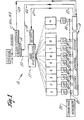
- Figure 1 shows a diagrammatic representation of the delivery control system embodying the present invention in relationship to other components of a glassware forming machine;
- Figure 2 shows a diagrammatic elevational view of one type of gob interceptor in relationship to other components associated with a glassware forming machine;
- Figure 3 shows graphical representations of the timing of various signals used in and produced by the invention;
- Figure 4 through Figure 6 show various flow charts describing the operation of a portion of the invention;
- Figures 7 and 8 show flow charts describing the operation of that portion of the invention dealing with interceptor supervision.
- Referring now to Figure 1 there is shown a diagrammatic representation of a
delivery control system 10 interconnected with aglassware forming machine 12.Machine 12 is also operatively connected togob interceptor 14, an interceptor activation sensors 16a and 16b and agob distributor 17 and its retract mechanism 18.Machine 12 comprises a plurality of individual sections labeled 1-N, the timing of each section being controlled byidentical controllers 20, each section forming glassware using, for example, the blow-and-blow process. - The feeder, shears, interceptor and distributor associated with
machine 12 are shown in greater detail in Figure 2. Innormal operation interceptor 14 is held retracted byinterceptor actuator mechanism 22 to enable a gob to drop alongline 23 from the feeder todistributor 17. When a gob is to be intercepted,interceptor actuator mechanism 22 causesinterceptor 14 to be extended to the intercept position shown in phantom in Figure 2, to deflect a gob intocullet chute 24. - In normal operation, each
controller 20 cyclically produces respectivedelivery activation signals 30, best seen in Figures 3a, 3b and 3c. It will be understood that each section producesphased signals 30 although only three are shown here.Delivery control system 10 outputs to the interceptor the composite signal shown in Figure 3d, unless certain conditions occur to turn the interceptor off, i.e. put it into the intercept position. The times shown in Figure 3 are with respect to the machine cycle, thus each section'ssignal 30 may extend for a 36° portion of the machine cycle for a 10 section machine. Eachsignal 30 operates similarly to the others except for the time of occurrence, therefore only onesignal 30 will be described. -
Signal 30 is a pulse going on at Ton and off at Toff. Both Ton and Toff are times relative to the machine cycle as opposed to the section cycle and vary among the sections. When high, signal 30 causesinterceptoractuator mechanism 22 to retractinterceptor 14 and hold. it in retracted position. - As will be seen below,
system 10 produces time windows A and B as seen in Figure 3b (not to scale) and supervises the occurrence ofsignal 30 to assure that its leading and trailing edges occur within the respective windows. Window A is defined as a time period from Ton - toll to Ton + toll and window B is defined as the time period from Toff - tol2 to Toff + tol2. The values tol1 and tol2 are predetermined tolerances, programmed intosystem 10 by the machine operator (or'preset in read only memory) and may be, for example, on the order of 1 to 2 degrees. - While the duration of
signal 30 from a section may be 360, in practice actual gob delivery can occur to that section only during a much smaller time period because of the movements of various section components. Window A defines that smaller time period. Also, it is desirable that Ton + toll does not overlap Toff - tol2 because of the interference presented by these components. As will be recognized by those skilled in the art, these moving parts (for example, a baffle, funnel, etc.) may interfere with clear delivery of the gob into the blank mold. It is also important thatsignal 30 not go off before Toff - tol2. This might cause the interceptor to be turned off while a gob is coming down for delivery to the next succeeding section. This would propel the molten gob into the plant with obvious hazardous consequences. - Returning to Figure 1, the
timing pulse generator 35 provides timing pulses for synchronizing thesection controllers 20 and for providing a machine cycle reference. The delivery enable pulse signal of eachcontroller 20 passes vialines 40 tosystem 10 which ultimately produces a composite signal (Figure 3d) tointerceptor 14 vialine 45. If the leading or trailing edge of one of thesignals 30 from a section should happen to occur outside its respective allowable time window,system 10 will turn the composite signal off andcommand interceptor 14 vialine 45 into the intercept position.System 10 also monitors the intercept and delivery positions of the interceptor vialine 45. If the interceptor does not reach the position to which it has been commanded within a predetermined time,system 10 will command gob distributor retract mechanism 18 via line 47 to retract. - In the preferred embodiment of the invention
delivery control system 10 is programmable and operates in conjunction with a programmable machine controller for controlling the timing of the various components within a glassware forming machine. The machine controller (not shown) is controlled by a main program andsystem 10 is controlled by a subroutine, the flow charts of which are shown in Figures 4 - 8. This subroutine is interrupt driven and monitors and controls delivery to each section of the machine although only operation with respect to one section will be described herein. - Figure 4 shows the flow chart.of a section delivery input interrupt service routine. A transition monitoring circuit 402 is.used to monitor
signal 30 from each section and produce an interrupt to the main program to initiate the routine at each transition (leading or trailing edge) ofsignal 30. The routine is sensitive to level transitions rather than to steady state conditions and the operation of the routine described below is designed to determine relevant level transitions. - At each interrupt the routine proceeds to decision block 404 to determine whether the delivery control function was selected for the particular section active at the time of the interrupt. This block enables machine operation without the delivery control function being enabled. If delivery control was not selected, the program branches to point A which will be discussed below. If it was, the program branches to decision block 406 to determine if the initialization mode has been completed. The initialization of
system 10 occurs automatically for the first machine cycle after the operator selects the delivery control function. The first time any transition interrupt causes the routine to run, the program will run throughdecision block 406, branch to point D and proceed along a subroutine more clearly shown in Figure 5. The second and subsequent times the program runs it will branch to processing block 408 where the polarity ofsignal 30 is read to determine whether it is high (on) or low (off).Decision block 410 then determines which transition caused the interrupt. Ifsignal 30 has transitioned from off to on, the program branches to decision block 412 to determine if the transition is valid. That is, whether or not the transition is within a valid window. If the transition is invalid, the program branches to processing block 414 which concludes that the delivery "on" timing is incorrect and turns off the section's delivery function. The program then proceeds toprocessing block 416, causing an error message to be logged into an appropriate display, and to point C, best seen in Figure 7. - Returning now to decision block 412, in the event the on to off transition is determined valid the program branches to processing block 420 which latches the
system 10 output to theinterceptor 14 to the state ofsignal 30, whichever polarity has been read byblock 408. The program then proceeds to Point B which initiates the interceptor activation control interrupt service routine more fully explained in Figure 7. - Returning now to decision block 410, in the
event signal 30 is determined to be off the program branches to decision block 430 which functions similarly to decision block 412 and determines whether the off status is a result of a valid transition. If it is, the program branches to processing block 420 and proceeds accordingly as described above. In the event the transition is invalid the program branches toprocessing blocks decision block 440 then determines if the other on delivery pulses are valid. If not, block 442 stops the delivery pulse of the other invalid section or sections and the program proceeds to point A. If so, the program proceeds to point C the output to the interceptor being left on.Blocks 438 to 442 prevent situations which might erroneously turn off the interceptor during valid delivery periods to other sections (e.g. when the delivery pulse of one section turns off after window B). - It will be noted that an invalid delivery "on" signal directs the program to point C while an invalid delivery "off" signal directs the program to point A, even though both invalid signals cause the section's delivery function to be disabled. The reason for the distinction is that if an error occurs in the timing of the trailing edge of a
signal 30 the interceptor will be commanded to go to an intercept position from a previous delivery position. To assure that the interceptor is turned off and the "off" invalidity is propagated through to the interceptor, process block 432 turns off the section's delivery function and, as an additional safety feature, the program goes through point A to block 420 setting thesystem 10 delivery output tointerceptor 14 to the off position. If the error, on the other hand, occurs in the leading edge, the polarity of the signal before the transition was low indicating the interceptor was off, so it should be left off. If the program were to branch-to block 420 thesystem 10 delivery output would be set high which would contradict the invalidity determined byblock 412. This is prevented by branching the program to point C after setting the section's delivery function off. Setting a section's delivery function off has the effect of leaving it off for all future cycles of that section until reset by the operator (by means not shown). - Referring now to Figure 5, the operation of the program will be described from point D on Figure 4. If
decision block 406 indicates that the operator has selected the delivery control mode for the section and the current cycle is the first one after such selection, the program proceeds to processing block 502 to read a degree counter representative of the angular position of the machine cycle at the time of the interrupt. The operator would activate delivery control when the particular section was running properly, so the various interrupt times would be acceptable. The program then proceeds to predefined process block 504 which performs a predetermined series of steps (shown'in phantom) to initialize both "on" and "off" events, as follows: - During the first cycle following selection of the delivery control function the system assigns a degree value to a plurality of events associated with each section. In the preferred embodiment each section is allocated four delivery events: (1) set on valid, (2) set on invalid, (3) set off valid, and (4) set off invalid. In a 10 section machine there would be total of forty events. As each transition interrupt occurs (Figure 4) the program branches to point D (Figure 5) to set an initial condition for that particular transition. For example, if the transition is an off to on transition and the initialization mode is selected by
block 406, predefined process block 504 would perform the functions in the right branch. That is, process block 506 would enter into memory an event labelled "set on valid" corresponding to a machine cycle angle equal to the degree counter number minus tol1. The program proceeds to process block 508 to enter an event "set on invalid" at an angle = degree counter + toll. The program then proceeds to processing block 510 to clear the selection of the initialization mode for the "on" events for the chosen section and returns the program to point A in Figure 4. After all events have been initialized,decision block 406 will branch to process block 408 at each interrupt. - A parallel procedure is followed with respect to the "off" events. The program proceeds to processing blocks 512, 514 and 516 to enter an event "set off valid" at an angle = degree counter - tol2 and an event "set off invalid" at an angle = degree counter + tol2. All events are stored in a circular linked list format and, as will be seen below, each event is sequentially accessed when the current machine angle corresponds to the event's angle of operation.
- Referring now to Figure 6, there is shown the flow chart of the operation of the delivery control event drivers which set the events to define valid time windows. Initially, it will be understood that the main program is driven by a 1 msec interrupt diagrammatically shown at point 6Q2. At each interrupt the main program branches to processing block 604 to update a degree counter to the then current machine angle relative to the timing reference pulse from
pulse operator 35. The main program then branches to decision block 606 to determine if there are any machine functions at this angle. If not, the program branches to "continue" via point F, explained below. If so, the main program branches to a subroutine viadecision block 608,to determine if the function is a delivery control event (i.e. an event set in Figure 5). If it is not, the routine branches to "continue" and returns control to the main program until the next interrupt. If it is, the program branches to decision block 610 to determine if the function is an on event or an off event (i.e.events events Decision block 618 andprocessing blocks 620 and 622 perform a similar function with respect to the window B utilized by decision block 430 (Figure 4) to determine validity of an off transition. While the delivery states are chosen herein to be updated at every interrupt the system would also operate properly if the delivery states were set only once in a look-up table. - In operation, while the machine is running, at each 1 msec interrupt the program checks to see if a delivery control event is called for at a machine angle. If so, the program sets the delivery state accordingly ("on" valid or invalid, or "off" valid or invalid) and when the transition interrupt (Figure 4) occurs, blocks 412 or 430 compare the transition to this delivery state to determine validity.
- Referring now to Figure 7, there is shown the flow chart for the interceptor activation control interrupt service routine. This routine is initiated from Point B, Figure 4, after each sections.'s delivery enable pulse to the interceptor has been latched either on or off.
Decision block 702 first determines if interceptor actuation supervision has been selected. If not, the routine branches to point C to "interrupt exit" and continues. If so, the routine branches to process block 704 to initialize an activation counter whether the interceptor is being turned on or off.Decision block 706 then determines whether the interceptor is being turned on or off and initializes an "on" latency counter to zero viablock 708 or an "off" latency counter to zero viablock 710, as the case may be. The program then continues to "interrupt exit," the intercept control function being more fully described in Figure 8. - A 1 msec interrupt initiates the-routine at
point 802. The routine services both on and off intercept control functions but, since they are similar, only the on function will be described. A diagrammatic representation of the intercept control timing function is shown in Figures 3e and 3f. Figure 3e represents a section's delivery enablepulse 30 and Figure 3f represents the interceptor's response thereto. (Note that if there is no transition in the delivery enable pulse the interceptor will not change its state and will therefore not need to be monitored). There is a time lag between the two due to inertia, if for no other reason. The time at which the interceptor reaches the intercept position is defined as Tact off and is determined by the output of sensor 16a which monitors the proper intercept position. The time at which the interceptor reaches a delivery position is defined as Tact on and is determined by sensor 16b which monitors the proper delivery position. Tact on and Tact off should be less than some maximum limits which may be preprogrammed or programmed by the operator. -
Processing block 804 increments the "on" latency counter by one and decision block 806 then determines if the count in the "on" latency counter is less than or equal to the maximum permitted (i.e. if Tact on - Ton is less than or equal to maximum). If the count equals the maximum, the routine proceeds to processing block 808 to check interceptor position sensor 16a to determine, indecision block 810, if the interceptor has reached the intercept position. If either the count is less than the maximum or if the interceptor has reached the intercept position, the routine branches to "continue." If not,processing block 812 indicates an interceptor failure to block 814 which causesgob distributor 17 to retract.Processing block 816 then logs an error message and returns the routine to "continue." The operator must then take approriate action. - While the preferred embodiment has been disclosed relative to an oscillating type of gob distributor', the invention is also suitable for reciprocating scoop type gob distributors (not shown) which operate without a separate gob interceptor.
- Those skilled in the art will understand that numerous other modifications and improvements may be made to the preferred embodi-ment of the invention disclosed herein without departing from the spirit and scope thereof.
Claims (13)
Applications Claiming Priority (2)
| Application Number | Priority Date | Filing Date | Title |
|---|---|---|---|
| US06/403,245 US4453963A (en) | 1982-07-29 | 1982-07-29 | Method and apparatus for controlling the delivery of gobs to a section of a glassware forming machine |
| US403245 | 1982-07-29 |
Publications (3)
| Publication Number | Publication Date |
|---|---|
| EP0100239A2 true EP0100239A2 (en) | 1984-02-08 |
| EP0100239A3 EP0100239A3 (en) | 1985-04-10 |
| EP0100239B1 EP0100239B1 (en) | 1988-09-14 |
Family
ID=23595062
Family Applications (1)
| Application Number | Title | Priority Date | Filing Date |
|---|---|---|---|
| EP83304328A Expired EP0100239B1 (en) | 1982-07-29 | 1983-07-27 | Method and apparatus for controlling the delivery of gobs to a section of a glassware forming machine |
Country Status (5)
| Country | Link |
|---|---|
| US (1) | US4453963A (en) |
| EP (1) | EP0100239B1 (en) |
| JP (1) | JPS5997538A (en) |
| AU (1) | AU1684783A (en) |
| DE (1) | DE3377982D1 (en) |
Cited By (9)
| Publication number | Priority date | Publication date | Assignee | Title |
|---|---|---|---|---|
| EP0180394A1 (en) * | 1984-10-27 | 1986-05-07 | Emhart Industries, Inc. | Control of apparatus for use in the manufacture of glassware articles |
| US4694158A (en) * | 1984-10-02 | 1987-09-15 | Verrerie du Languedoc et Cie | Contactless inspection of objects with feedback to high speed manufacturing device |
| EP0281300A3 (en) * | 1987-03-02 | 1989-12-06 | Emhart Industries, Inc. | Gob distributor |
| EP0281301A3 (en) * | 1987-03-02 | 1989-12-06 | Emhart Industries, Inc. | Gob distributor |
| EP0376740A3 (en) * | 1988-12-30 | 1993-06-16 | Pitney Bowes Inc. | Asynchronous rejection in an inserter |
| EP0488136A3 (en) * | 1990-11-28 | 1993-10-20 | Ishizuka Glass | Glass bottle forming machine |
| EP0574349A1 (en) * | 1992-05-18 | 1993-12-15 | Janusz Sadokierski | Method for improving the quality during the manufacture of glass bottles |
| EP0603010A3 (en) * | 1992-12-18 | 1995-03-29 | Emhart Glass Mach Invest | Machine for forming glass containers. |
| EP0801036A3 (en) * | 1996-04-10 | 1998-01-07 | Gps Glasproduktions-Service Gmbh | Method for controlling the blank molds of a glass-machine with several like sections next to each other |
Families Citing this family (10)
| Publication number | Priority date | Publication date | Assignee | Title |
|---|---|---|---|---|
| MX153641A (en) * | 1983-05-19 | 1986-10-14 | Vitro Tec Fideicomiso | IMPROVEMENTS IN AUTOMATIC CONTROLLER FOR GLASS ARTICLE FORMING MACHINES |
| DE3342062C2 (en) * | 1983-11-22 | 1986-10-30 | Ruhrglas AG, 4300 Essen | Circuit arrangement for controlling a gob distributor of a glass processing machine |
| US4548637A (en) * | 1984-08-30 | 1985-10-22 | Owens-Illinois, Inc. | Servo-control of machine motions in manufacture of glass containers |
| US4599101A (en) * | 1985-05-15 | 1986-07-08 | Emhart Industries, Inc. | Universal servo-driven gob distributor |
| US5405424A (en) * | 1993-05-24 | 1995-04-11 | Owens-Brockway Glass Container Inc. | Servo controlled glass gob distributor |
| US5746798A (en) * | 1993-07-16 | 1998-05-05 | Owens-Brockway Glass Container Inc. | Control of glass gob delivery for simultaneous arrival at blank molds |
| US5697995A (en) * | 1996-04-30 | 1997-12-16 | Owens-Brockway Glass Container Inc. | Belt-driven glass gob distribution with broken belt detection |
| DE50108087D1 (en) * | 2001-06-12 | 2005-12-22 | Glas Heinz Gmbh | Method and device for the simultaneous production of glass products of different mass |
| US7146215B1 (en) | 2001-06-13 | 2006-12-05 | Pacesetter, Inc. | Multi-site cardiac stimulation device and method for detecting retrograde conduction |
| US6611714B1 (en) | 2001-06-13 | 2003-08-26 | Pacesetter, Inc. | Multi-site cardiac stimulation device and method for detecting retrograde conduction |
Family Cites Families (4)
| Publication number | Priority date | Publication date | Assignee | Title |
|---|---|---|---|---|
| US2955383A (en) * | 1958-01-21 | 1960-10-11 | Owens Illinois Glass Co | Gob guiding apparatus |
| US3721544A (en) * | 1971-11-17 | 1973-03-20 | Emhart Corp | Molten glass gob distribution system |
| US4266961A (en) * | 1978-04-20 | 1981-05-12 | Ball Corporation | Override system for glass forming machinery |
| CA1131031A (en) * | 1979-02-06 | 1982-09-07 | Homer D. F. Peters | Hot gob detector for a glassware forming machine |
-
1982
- 1982-07-29 US US06/403,245 patent/US4453963A/en not_active Expired - Lifetime
-
1983
- 1983-07-14 AU AU16847/83A patent/AU1684783A/en not_active Abandoned
- 1983-07-27 DE DE8383304328T patent/DE3377982D1/en not_active Expired
- 1983-07-27 EP EP83304328A patent/EP0100239B1/en not_active Expired
- 1983-07-29 JP JP58139304A patent/JPS5997538A/en active Granted
Cited By (9)
| Publication number | Priority date | Publication date | Assignee | Title |
|---|---|---|---|---|
| US4694158A (en) * | 1984-10-02 | 1987-09-15 | Verrerie du Languedoc et Cie | Contactless inspection of objects with feedback to high speed manufacturing device |
| EP0180394A1 (en) * | 1984-10-27 | 1986-05-07 | Emhart Industries, Inc. | Control of apparatus for use in the manufacture of glassware articles |
| EP0281300A3 (en) * | 1987-03-02 | 1989-12-06 | Emhart Industries, Inc. | Gob distributor |
| EP0281301A3 (en) * | 1987-03-02 | 1989-12-06 | Emhart Industries, Inc. | Gob distributor |
| EP0376740A3 (en) * | 1988-12-30 | 1993-06-16 | Pitney Bowes Inc. | Asynchronous rejection in an inserter |
| EP0488136A3 (en) * | 1990-11-28 | 1993-10-20 | Ishizuka Glass | Glass bottle forming machine |
| EP0574349A1 (en) * | 1992-05-18 | 1993-12-15 | Janusz Sadokierski | Method for improving the quality during the manufacture of glass bottles |
| EP0603010A3 (en) * | 1992-12-18 | 1995-03-29 | Emhart Glass Mach Invest | Machine for forming glass containers. |
| EP0801036A3 (en) * | 1996-04-10 | 1998-01-07 | Gps Glasproduktions-Service Gmbh | Method for controlling the blank molds of a glass-machine with several like sections next to each other |
Also Published As
| Publication number | Publication date |
|---|---|
| JPS6365611B2 (en) | 1988-12-16 |
| EP0100239B1 (en) | 1988-09-14 |
| US4453963A (en) | 1984-06-12 |
| JPS5997538A (en) | 1984-06-05 |
| EP0100239A3 (en) | 1985-04-10 |
| AU1684783A (en) | 1984-02-02 |
| DE3377982D1 (en) | 1988-10-20 |
Similar Documents
| Publication | Publication Date | Title |
|---|---|---|
| US4453963A (en) | Method and apparatus for controlling the delivery of gobs to a section of a glassware forming machine | |
| US4459146A (en) | Electronic control system in a glassware forming machine | |
| SU1034601A3 (en) | Automatic control system of machine for making glass products | |
| US4685947A (en) | Glassware forming apparatus with distributed control and method of operation | |
| US5445662A (en) | Glass container forming machine with a controller for controlling controllers | |
| US4615723A (en) | Intelligent controller for predicting and automatically compensating for variations in cycle time, in machines for forming articles of glass or other materials | |
| US4313750A (en) | Electronically controlled robot for handling glassware | |
| US4375669A (en) | Electronic control system for a glassware forming machine | |
| US4338115A (en) | Starting safety control for a glassware forming machine | |
| US5746798A (en) | Control of glass gob delivery for simultaneous arrival at blank molds | |
| EP0117075B1 (en) | Programmable control system for glassware forming machines | |
| US4469501A (en) | Timing control system for glassware forming machine | |
| CA2203358C (en) | Belt-driven glass gob distribution with broken belt detection | |
| EP0105716B1 (en) | Individually controlled interceptors for glass forming machines | |
| CA1134147A (en) | Hot gob detector for a glassware forming machine | |
| WO1986004432A1 (en) | Redundant control system for automatic forming machine | |
| USRE30998E (en) | Hot gob detector for controlling a glassware forming machine | |
| GB1603754A (en) | Concerning a cyclically operating container forming machine | |
| JPS6021927B2 (en) | Timing value dwell inversion for electronic control of glassware forming machines. protection |
Legal Events
| Date | Code | Title | Description |
|---|---|---|---|
| PUAI | Public reference made under article 153(3) epc to a published international application that has entered the european phase |
Free format text: ORIGINAL CODE: 0009012 |
|
| AK | Designated contracting states |
Designated state(s): DE FR GB IT |
|
| PUAL | Search report despatched |
Free format text: ORIGINAL CODE: 0009013 |
|
| AK | Designated contracting states |
Designated state(s): DE FR GB IT |
|
| 17P | Request for examination filed |
Effective date: 19850724 |
|
| 17Q | First examination report despatched |
Effective date: 19860812 |
|
| GRAA | (expected) grant |
Free format text: ORIGINAL CODE: 0009210 |
|
| AK | Designated contracting states |
Kind code of ref document: B1 Designated state(s): DE FR GB IT |
|
| REF | Corresponds to: |
Ref document number: 3377982 Country of ref document: DE Date of ref document: 19881020 |
|
| ET | Fr: translation filed | ||
| ITF | It: translation for a ep patent filed | ||
| PGFP | Annual fee paid to national office [announced via postgrant information from national office to epo] |
Ref country code: GB Payment date: 19890630 Year of fee payment: 7 |
|
| PGFP | Annual fee paid to national office [announced via postgrant information from national office to epo] |
Ref country code: DE Payment date: 19890706 Year of fee payment: 7 |
|
| PGFP | Annual fee paid to national office [announced via postgrant information from national office to epo] |
Ref country code: FR Payment date: 19890707 Year of fee payment: 7 |
|
| PLBE | No opposition filed within time limit |
Free format text: ORIGINAL CODE: 0009261 |
|
| STAA | Information on the status of an ep patent application or granted ep patent |
Free format text: STATUS: NO OPPOSITION FILED WITHIN TIME LIMIT |
|
| ITTA | It: last paid annual fee | ||
| 26N | No opposition filed | ||
| PG25 | Lapsed in a contracting state [announced via postgrant information from national office to epo] |
Ref country code: GB Effective date: 19900727 |
|
| GBPC | Gb: european patent ceased through non-payment of renewal fee | ||
| PG25 | Lapsed in a contracting state [announced via postgrant information from national office to epo] |
Ref country code: FR Effective date: 19910329 |
|
| PG25 | Lapsed in a contracting state [announced via postgrant information from national office to epo] |
Ref country code: DE Effective date: 19910403 |
|
| REG | Reference to a national code |
Ref country code: FR Ref legal event code: ST |