EP0099237B1 - Nuclear magnetic resonance imaging apparatus - Google Patents
Nuclear magnetic resonance imaging apparatus Download PDFInfo
- Publication number
- EP0099237B1 EP0099237B1 EP83303934A EP83303934A EP0099237B1 EP 0099237 B1 EP0099237 B1 EP 0099237B1 EP 83303934 A EP83303934 A EP 83303934A EP 83303934 A EP83303934 A EP 83303934A EP 0099237 B1 EP0099237 B1 EP 0099237B1
- Authority
- EP
- European Patent Office
- Prior art keywords
- heat treatment
- temperature
- region
- treatment means
- spatial variation
- Prior art date
- Legal status (The legal status is an assumption and is not a legal conclusion. Google has not performed a legal analysis and makes no representation as to the accuracy of the status listed.)
- Expired
Links
Images
Classifications
-
- G—PHYSICS
- G01—MEASURING; TESTING
- G01R—MEASURING ELECTRIC VARIABLES; MEASURING MAGNETIC VARIABLES
- G01R33/00—Arrangements or instruments for measuring magnetic variables
- G01R33/20—Arrangements or instruments for measuring magnetic variables involving magnetic resonance
- G01R33/44—Arrangements or instruments for measuring magnetic variables involving magnetic resonance using nuclear magnetic resonance [NMR]
- G01R33/48—NMR imaging systems
- G01R33/50—NMR imaging systems based on the determination of relaxation times, e.g. T1 measurement by IR sequences; T2 measurement by multiple-echo sequences
-
- A—HUMAN NECESSITIES
- A61—MEDICAL OR VETERINARY SCIENCE; HYGIENE
- A61B—DIAGNOSIS; SURGERY; IDENTIFICATION
- A61B5/00—Measuring for diagnostic purposes; Identification of persons
- A61B5/05—Detecting, measuring or recording for diagnosis by means of electric currents or magnetic fields; Measuring using microwaves or radio waves
- A61B5/055—Detecting, measuring or recording for diagnosis by means of electric currents or magnetic fields; Measuring using microwaves or radio waves involving electronic [EMR] or nuclear [NMR] magnetic resonance, e.g. magnetic resonance imaging
-
- G—PHYSICS
- G01—MEASURING; TESTING
- G01R—MEASURING ELECTRIC VARIABLES; MEASURING MAGNETIC VARIABLES
- G01R33/00—Arrangements or instruments for measuring magnetic variables
- G01R33/20—Arrangements or instruments for measuring magnetic variables involving magnetic resonance
- G01R33/44—Arrangements or instruments for measuring magnetic variables involving magnetic resonance using nuclear magnetic resonance [NMR]
- G01R33/48—NMR imaging systems
- G01R33/4804—Spatially selective measurement of temperature or pH
Definitions
- This invention relates to nuclear magnetic resonance (NMR) imaging apparatus.
- NMR imaging apparatus can be used to examine the spatial distribution over a selected cross-sectional slice or volume of a body of a chosen quantity, for example, the density of chosen protons such as hydrogen nuclei, or NMR spin relaxation time constants.
- Such distributions are similar to, although of different significance from, the distributions of X-ray attenuation provided by computerised X-ray tomography systems.
- an NMR imaging apparatus is associated with heat treatment means and is arranged to examine, whilst the heat treatment means is being operated to subject a region of the body to heat treatment, the spatial variation of the spin lattice relaxation time constant (T1) in a part of said body including said region, thereby to obtain an indication of the spatial variation of the temperature in said part of the body during treatment.
- T1 spin lattice relaxation time constant
- NMR imaging apparatus to indicate spatial variation of temperature in a body subjected to heat treatment arises from the fact that in a simple liquid the NMR spin lattice relaxation time constant (T,) is a function of temperature, the relationship being of the form where T is absolute temperature; and n is the viscosity of the liquid.
- T NMR spin lattice relaxation time constant
- the viscosity of a simple liquid is highly dependent on temperature, so that, for example for water, a 12% change in T, may be expected for a temperature rise of 35°C to 40°C.
- an apparatus in accordance with the invention may be used to monitor accurately, on- line, whilst the heat treatment is being applied, the heating effect of the heat treatment on the material being treated.
- the invention finds particular application where the heat treatment means is a hyperthermia treatment means.
- Hyperthermia treatment comprises subjecting material, more especially diseased tissue of a patient, to microwave energy so as to raise the temperature of the material.
- the treatment is typically such as to raise the temperature of the tissue by about 6°C, i.e. to about 43°C for human tissue, sufficient to denature protein in the tissue.
- EP-A-0095124 which falls within the terms of Article 54(3) EPC.
- temperature measurement is effected on the basis of measurement of chemical shift, not spin lattice relaxation time constant.
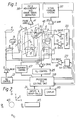
- FIGS 1 and 2 illustrate the apparatus diagrammatically.
- the apparatus is to a large extent of conventional form, for example, as described in United Kingdom Patent Specification No. 1,578,910 or No. 2,056,078 to which reference should be made for a fuller description of the apparatus.
- the apparatus includes a first coil system whereby a magnetic field can be applied to a body to be examined in a given direction, normally designated the Z-direction, with a gradient in any one or more of the three orthogonal directions i.e. X, Y and Z directions.
- the first coil system comprises coils 1 which provide a steady uniform magnetic field B o in the Z-direction; coils 3 which provide a magnetic field gradient Gx in the X-direction, coils 5 which provide a magnetic field gradient Gy in the Y-direction; and coils 7 which provide a magnetic field gradient G z in the Z-direction.
- the apparatus includes a second coil system 9 whereby RF magnetic fields can be applied to the body under examination in a plane normal to the direction of the magnetic field produced by the first coil system, and whereby RF magnetic fields resulting from nuclei in the body under examination which have been excited to nuclear magnetic resonance with a spin vector component other than in the Z-direction can be detected.
- the various coils 1, 3, 5, 7 and 9 are driven by B o , G x , Gy, G z and RF drive amplifiers 11, 13, 15, 17 and 19 respectively, controlled by B a , G X y, G z and RF control circuits 21, 23, 25 and 27 respectively.
- These circuits may take various forms which are well known to those with experience of NMR equipment and other apparatus using coil induced magnetic fields.
- the circuits 21, 23. 25 and 27 are controlled by a central processing and control unit 29 with which are associated inputs and other peripherals 31, for the provision of commands and instructions to the apparatus, and a display 33.
- the NMR signals detected by the coils 9 are applied via an amplifier 35 to a signal handling system 37.
- the signal handling system is arranged to make any appropriate calibration and correction of the signals, but essentially transmits the signals to the processing and control unit 29 wherein the signals are processed for application to the display to produce an image representing the distribution of an NMR quantity in the body being examined.
- the signal handling system 37 may conveniently form part of the unit 29.
- the apparatus also includes field measurement and error signal circuits 39 which receive signals via amplifiers 41 from field probes X" X 2 , Y, and Y 2 which are disposed at suitable positions in relation to a slice 43 of the body being examined, as illustrated in Figure 2, to monitor the applied magnetic fields.
- the apparatus further includes hyperthermia treatment means 45 whereby a selected region of the body under examination may be subjected to hyperthermia treatment.
- the treatment means 45 operates under control of a control means 47 which in turn may be controlled by the central processing control unit 29, as further described below.
- the hyperthermia treatment means typically comprises means such as a waveguide injector, for direct injection of microwave energy into a selected region of the body under examination.
- the hyperthermia treatment means may comprise one of or more microwave energy radiators which are operated so as to minimise the heat produced in all except an internal target region of the body, for example, by mechanical movement in the case of a single radiator, or by appropriate switching in the case of a plurality of fixed radiators.
- the apparatus is operated in well known manner to obtain an image representative of the spatial variation of the NMR spin lattice relaxation time (T,) of appropriate protons, normally hydrogen nuclei, in a region of the body including the region which is to be subjected to hyperthermia treatment.
- T NMR spin lattice relaxation time
- Such an image may for example be obtained using a so-called inversion recovery sequence and any desired image reconstruction technique such as a back projection technique or a Fourier transformation technique.
- the hyperthermia treatment means When an image has been established the hyperthermia treatment means is switched on and the NMR image is used to monitor the spin lattice relaxation time and hence the temperature of the material being subjected to the hyperthermia treatment.
- the hyperthermia treatment means may then be controlled so as to prevent excessive heating of any part of the imaged area of the body e.g. so that areas not being treated do not approach 43°C and so that the areas to be treated are not excessively heated.
- the control means 47 may be controlled automatically by an output signal produced by the processing and control unit.
- a visual representation of spin lattice relaxation time image may be displayed on the display 33 and approriate action taken to prevent excessive heating by an operator viewing the image.
- the image may also be used by the operator to position the hyperthermia treatment means so that the desired target area of the body is subjected to hyperthermia treatment.
- the processing and control unit 29 may also be arranged to control the imaging and hyperthermia treatment functions of the apparatus so as to minimise interference of the hyperthermia function with the imaging function.
- NMR parameter which is examined in an apparatus according to the invention is spin lattice relaxation time
- other NMR parameters may be examined not only to obtain a better representation of temperature variation, but also to obtain a better representation of the body structure, thereby to facilitate the identification of different regions of the body being examined.
Landscapes
- Physics & Mathematics (AREA)
- Health & Medical Sciences (AREA)
- Life Sciences & Earth Sciences (AREA)
- High Energy & Nuclear Physics (AREA)
- Condensed Matter Physics & Semiconductors (AREA)
- General Physics & Mathematics (AREA)
- Nuclear Medicine, Radiotherapy & Molecular Imaging (AREA)
- Heart & Thoracic Surgery (AREA)
- Animal Behavior & Ethology (AREA)
- Pathology (AREA)
- Engineering & Computer Science (AREA)
- Biomedical Technology (AREA)
- Radiology & Medical Imaging (AREA)
- Medical Informatics (AREA)
- Molecular Biology (AREA)
- Surgery (AREA)
- Biophysics (AREA)
- General Health & Medical Sciences (AREA)
- Public Health (AREA)
- Veterinary Medicine (AREA)
- Thermotherapy And Cooling Therapy Devices (AREA)
- Electrotherapy Devices (AREA)
- Magnetic Resonance Imaging Apparatus (AREA)
- Radiation-Therapy Devices (AREA)
Description
- This invention relates to nuclear magnetic resonance (NMR) imaging apparatus.
- NMR imaging apparatus can be used to examine the spatial distribution over a selected cross-sectional slice or volume of a body of a chosen quantity, for example, the density of chosen protons such as hydrogen nuclei, or NMR spin relaxation time constants. Such distributions are similar to, although of different significance from, the distributions of X-ray attenuation provided by computerised X-ray tomography systems.
- According to the present invention an NMR imaging apparatus is associated with heat treatment means and is arranged to examine, whilst the heat treatment means is being operated to subject a region of the body to heat treatment, the spatial variation of the spin lattice relaxation time constant (T1) in a part of said body including said region, thereby to obtain an indication of the spatial variation of the temperature in said part of the body during treatment.
- The ability of an NMR imaging apparatus to indicate spatial variation of temperature in a body subjected to heat treatment arises from the fact that in a simple liquid the NMR spin lattice relaxation time constant (T,) is a function of temperature, the relationship being of the form

- The viscosity of a simple liquid is highly dependent on temperature, so that, for example for water, a 12% change in T, may be expected for a temperature rise of 35°C to 40°C.
- Hence, an apparatus in accordance with the invention may be used to monitor accurately, on- line, whilst the heat treatment is being applied, the heating effect of the heat treatment on the material being treated.
- The invention finds particular application where the heat treatment means is a hyperthermia treatment means.
- Hyperthermia treatment comprises subjecting material, more especially diseased tissue of a patient, to microwave energy so as to raise the temperature of the material. In the case of diseased tissue, the treatment is typically such as to raise the temperature of the tissue by about 6°C, i.e. to about 43°C for human tissue, sufficient to denature protein in the tissue.
- It is most important in hyperthermia treatment that only the target diseased tissue, and not healthy tissue, should be heated. An apparatus in accordance with the invention enables this to be successfully achieved.
- An NMR apparatus which is capable of providing an indication of spatial variation of temperature in a body undergoing heat treatment is described in EP-A-0095124 which falls within the terms of Article 54(3) EPC. However, in the apparatus of EP-A-0095124 temperature measurement is effected on the basis of measurement of chemical shift, not spin lattice relaxation time constant.
- One NMR imaging apparatus in accordance with the invention will now be described, by way of example, with reference to the accompanying drawing in which:-
- Figures 1 and 2 illustrate the apparatus diagrammatically.
- The apparatus is to a large extent of conventional form, for example, as described in United Kingdom Patent Specification No. 1,578,910 or No. 2,056,078 to which reference should be made for a fuller description of the apparatus.
- The essential features of such apparatus and its method of operation, in so far as is necessary for an understanding of the present invention, are as follows:-x
- The apparatus includes a first coil system whereby a magnetic field can be applied to a body to be examined in a given direction, normally designated the Z-direction, with a gradient in any one or more of the three orthogonal directions i.e. X, Y and Z directions.
- Referring to Figure 1, the first coil system comprises coils 1 which provide a steady uniform magnetic field Bo in the Z-direction;
coils 3 which provide a magnetic field gradient Gx in the X-direction,coils 5 which provide a magnetic field gradient Gy in the Y-direction; and coils 7 which provide a magnetic field gradient Gz in the Z-direction. - In addition, the apparatus includes a second coil system 9 whereby RF magnetic fields can be applied to the body under examination in a plane normal to the direction of the magnetic field produced by the first coil system, and whereby RF magnetic fields resulting from nuclei in the body under examination which have been excited to nuclear magnetic resonance with a spin vector component other than in the Z-direction can be detected.
- In the drawing a single pair of coils 9 is shown for both applying and detecting RF fields, but in certain circumstances it may be preferable to provide separate coils for detecting the RF fields.
- The
various coils RF drive amplifiers 11, 13, 15, 17 and 19 respectively, controlled by Ba, GXy, Gz andRF control circuits - The
circuits 21, 23. 25 and 27 are controlled by a central processing andcontrol unit 29 with which are associated inputs andother peripherals 31, for the provision of commands and instructions to the apparatus, and adisplay 33. - The NMR signals detected by the coils 9 are applied via an amplifier 35 to a
signal handling system 37. The signal handling system is arranged to make any appropriate calibration and correction of the signals, but essentially transmits the signals to the processing andcontrol unit 29 wherein the signals are processed for application to the display to produce an image representing the distribution of an NMR quantity in the body being examined. - It will be appreciated that whilst shown separately to clarify the present description, the
signal handling system 37 may conveniently form part of theunit 29. - The apparatus also includes field measurement and
error signal circuits 39 which receive signals viaamplifiers 41 from field probes X" X2, Y, and Y2 which are disposed at suitable positions in relation to aslice 43 of the body being examined, as illustrated in Figure 2, to monitor the applied magnetic fields. - In accordance with the present invention the apparatus further includes hyperthermia treatment means 45 whereby a selected region of the body under examination may be subjected to hyperthermia treatment. The treatment means 45 operates under control of a control means 47 which in turn may be controlled by the central
processing control unit 29, as further described below. - The hyperthermia treatment means typically comprises means such as a waveguide injector, for direct injection of microwave energy into a selected region of the body under examination. Alternatively, the hyperthermia treatment means may comprise one of or more microwave energy radiators which are operated so as to minimise the heat produced in all except an internal target region of the body, for example, by mechanical movement in the case of a single radiator, or by appropriate switching in the case of a plurality of fixed radiators.
- In use the apparatus is operated in well known manner to obtain an image representative of the spatial variation of the NMR spin lattice relaxation time (T,) of appropriate protons, normally hydrogen nuclei, in a region of the body including the region which is to be subjected to hyperthermia treatment.
- Such an image may for example be obtained using a so-called inversion recovery sequence and any desired image reconstruction technique such as a back projection technique or a Fourier transformation technique.
- When an image has been established the hyperthermia treatment means is switched on and the NMR image is used to monitor the spin lattice relaxation time and hence the temperature of the material being subjected to the hyperthermia treatment. The hyperthermia treatment means may then be controlled so as to prevent excessive heating of any part of the imaged area of the body e.g. so that areas not being treated do not approach 43°C and so that the areas to be treated are not excessively heated. To this end the control means 47 may be controlled automatically by an output signal produced by the processing and control unit. Alternatively or additionally, a visual representation of spin lattice relaxation time image may be displayed on the
display 33 and approriate action taken to prevent excessive heating by an operator viewing the image. The image may also be used by the operator to position the hyperthermia treatment means so that the desired target area of the body is subjected to hyperthermia treatment. - The processing and
control unit 29 may also be arranged to control the imaging and hyperthermia treatment functions of the apparatus so as to minimise interference of the hyperthermia function with the imaging function. - It will be appreciated that whilst in the embodiment of the invention described above by way of example the heat treatment involves raising the temperature of a region of a body, the invention is equally applicable to apparatus in which the heat treatment means cools a region of a body. The term heat treatment as used in the present specification and claims should therefore be interpreted accordingly.
- It is further pointed out that whilst the particular NMR parameter which is examined in an apparatus according to the invention is spin lattice relaxation time, it may in certain circumstances be desirable to examine additionally other NMR parameters. Such other parameters may be examined not only to obtain a better representation of temperature variation, but also to obtain a better representation of the body structure, thereby to facilitate the identification of different regions of the body being examined.
Claims (5)
Applications Claiming Priority (2)
| Application Number | Priority Date | Filing Date | Title |
|---|---|---|---|
| GB8219628 | 1982-07-07 | ||
| GB8219628 | 1982-07-07 |
Publications (3)
| Publication Number | Publication Date |
|---|---|
| EP0099237A2 EP0099237A2 (en) | 1984-01-25 |
| EP0099237A3 EP0099237A3 (en) | 1986-07-16 |
| EP0099237B1 true EP0099237B1 (en) | 1989-12-27 |
Family
ID=10531517
Family Applications (1)
| Application Number | Title | Priority Date | Filing Date |
|---|---|---|---|
| EP83303934A Expired EP0099237B1 (en) | 1982-07-07 | 1983-07-06 | Nuclear magnetic resonance imaging apparatus |
Country Status (5)
| Country | Link |
|---|---|
| US (1) | US4554925A (en) |
| EP (1) | EP0099237B1 (en) |
| JP (1) | JPS5925735A (en) |
| DE (1) | DE3381018D1 (en) |
| GB (1) | GB2123963B (en) |
Families Citing this family (59)
| Publication number | Priority date | Publication date | Assignee | Title |
|---|---|---|---|---|
| US4558279A (en) * | 1983-03-07 | 1985-12-10 | University Of Cincinnati | Methods for detecting and imaging a temperature of an object by nuclear magnetic resonance |
| US5188107A (en) * | 1985-10-08 | 1993-02-23 | Yoshiaki Omura | Bi-digital O-ring test for imaging and diagnosis of internal organs of a patient |
| IL86470A (en) * | 1988-05-23 | 1994-11-28 | E M T Electro Magnetic Technol | Remote temperature monitoring apparatus and technique |
| IL87649A (en) * | 1988-09-01 | 1992-07-15 | Elscint Ltd | Hyperthermic power delivery system |
| US5284144A (en) * | 1989-11-22 | 1994-02-08 | The United States Of America As Represented By The Secretary Of The Dept. Of Health & Human Services | Apparatus for hyperthermia treatment of cancer |
| WO1991007132A1 (en) * | 1989-11-22 | 1991-05-30 | The United States Of America, Represented By The Secretary, United States Department Of Commerce | Apparatus for hyperthermia treatment of cancer |
| JPH04126163A (en) * | 1990-06-13 | 1992-04-27 | Omron Corp | Thermotherapeutic device |
| ZA917281B (en) * | 1990-09-26 | 1992-08-26 | Cryomedical Sciences Inc | Cryosurgical instrument and system and method of cryosurgery |
| WO1992019264A1 (en) * | 1991-05-01 | 1992-11-12 | University Of New Mexico | Biomodulators as universal imaging agents |
| US5291890A (en) * | 1991-08-29 | 1994-03-08 | General Electric Company | Magnetic resonance surgery using heat waves produced with focussed ultrasound |
| US5275165A (en) * | 1992-11-06 | 1994-01-04 | General Electric Company | Magnetic resonance guided ultrasound therapy system with inclined track to move transducers in a small vertical space |
| EP0627206B1 (en) * | 1993-03-12 | 2002-11-20 | Kabushiki Kaisha Toshiba | Apparatus for ultrasound medical treatment |
| US5433717A (en) * | 1993-03-23 | 1995-07-18 | The Regents Of The University Of California | Magnetic resonance imaging assisted cryosurgery |
| US5307812A (en) * | 1993-03-26 | 1994-05-03 | General Electric Company | Heat surgery system monitored by real-time magnetic resonance profiling |
| US5492122A (en) * | 1994-04-15 | 1996-02-20 | Northrop Grumman Corporation | Magnetic resonance guided hyperthermia |
| DE4433502A1 (en) * | 1994-09-20 | 1996-03-21 | Siemens Ag | NMR tomographic appts. with high-frequency spin excitation transmitter |
| IT1289809B1 (en) * | 1996-12-27 | 1998-10-16 | Ist Trentino Di Cultura | PROCESS AND AUTOMATIC SYSTEM TO OBTAIN WATER CONTENT AND / OR ELECTRIC PERMITIVITY MAPS FROM RESONANCE IMAGES |
| DE19707451A1 (en) * | 1997-02-25 | 1998-08-27 | Werner Alois Prof Dipl Kaiser | Arrangement for magnetic resonance examination and hyperthermia treatment |
| US6272370B1 (en) | 1998-08-07 | 2001-08-07 | The Regents Of University Of Minnesota | MR-visible medical device for neurological interventions using nonlinear magnetic stereotaxis and a method imaging |
| ATE419789T1 (en) | 1997-05-23 | 2009-01-15 | Prorhythm Inc | HIGH INTENSITY DISPOSABLE FOCUSING ULTRASONIC APPLICATOR |
| DE19732120B4 (en) * | 1997-06-17 | 2006-02-09 | Erbe Elektromedizin Gmbh | Method and device for suppressing the effects of alternating electromagnetic field radiation of electromedical devices |
| US6198957B1 (en) * | 1997-12-19 | 2001-03-06 | Varian, Inc. | Radiotherapy machine including magnetic resonance imaging system |
| US6463317B1 (en) | 1998-05-19 | 2002-10-08 | Regents Of The University Of Minnesota | Device and method for the endovascular treatment of aneurysms |
| US6492762B1 (en) | 1999-03-22 | 2002-12-10 | Transurgical, Inc. | Ultrasonic transducer, transducer array, and fabrication method |
| JP3848572B2 (en) | 1999-09-10 | 2006-11-22 | プロリズム,インコーポレイテッド | Device for occluding anatomic tissue |
| US6618620B1 (en) | 2000-11-28 | 2003-09-09 | Txsonics Ltd. | Apparatus for controlling thermal dosing in an thermal treatment system |
| US6735461B2 (en) * | 2001-06-19 | 2004-05-11 | Insightec-Txsonics Ltd | Focused ultrasound system with MRI synchronization |
| US7542793B2 (en) * | 2002-08-22 | 2009-06-02 | Mayo Foundation For Medical Education And Research | MR-guided breast tumor ablation and temperature imaging system |
| US7270656B2 (en) | 2003-11-07 | 2007-09-18 | Visualase, Inc. | Cooled laser fiber for improved thermal therapy |
| US8409099B2 (en) * | 2004-08-26 | 2013-04-02 | Insightec Ltd. | Focused ultrasound system for surrounding a body tissue mass and treatment method |
| US8170643B2 (en) * | 2005-11-22 | 2012-05-01 | Bsd Medical Corporation | System and method for irradiating a target with electromagnetic radiation to produce a heated region |
| EP1960993B1 (en) | 2005-11-23 | 2016-11-02 | Insightec-Image Guided Treatment, Ltd. | Hierarchical switching in ultra-high density ultrasound array |
| EP2021846B1 (en) | 2006-05-19 | 2017-05-03 | Koninklijke Philips N.V. | Ablation device with optimized input power profile |
| US9403029B2 (en) | 2007-07-18 | 2016-08-02 | Visualase, Inc. | Systems and methods for thermal therapy |
| US8251908B2 (en) | 2007-10-01 | 2012-08-28 | Insightec Ltd. | Motion compensated image-guided focused ultrasound therapy system |
| US8425424B2 (en) | 2008-11-19 | 2013-04-23 | Inightee Ltd. | Closed-loop clot lysis |
| US8617073B2 (en) | 2009-04-17 | 2013-12-31 | Insightec Ltd. | Focusing ultrasound into the brain through the skull by utilizing both longitudinal and shear waves |
| US9623266B2 (en) | 2009-08-04 | 2017-04-18 | Insightec Ltd. | Estimation of alignment parameters in magnetic-resonance-guided ultrasound focusing |
| US9289154B2 (en) | 2009-08-19 | 2016-03-22 | Insightec Ltd. | Techniques for temperature measurement and corrections in long-term magnetic resonance thermometry |
| US20110046475A1 (en) * | 2009-08-24 | 2011-02-24 | Benny Assif | Techniques for correcting temperature measurement in magnetic resonance thermometry |
| US9177543B2 (en) | 2009-08-26 | 2015-11-03 | Insightec Ltd. | Asymmetric ultrasound phased-array transducer for dynamic beam steering to ablate tissues in MRI |
| EP2489034B1 (en) | 2009-10-14 | 2016-11-30 | Insightec Ltd. | Mapping ultrasound transducers |
| EP3132828B1 (en) | 2009-10-30 | 2017-10-11 | ReCor Medical, Inc. | Apparatus for treatment of hypertension through percutaneous ultrasound renal denervation |
| US8368401B2 (en) | 2009-11-10 | 2013-02-05 | Insightec Ltd. | Techniques for correcting measurement artifacts in magnetic resonance thermometry |
| US8810246B2 (en) * | 2010-01-19 | 2014-08-19 | Insightec Ltd. | Hybrid referenceless and multibaseline PRF-shift magnetic resonance thermometry |
| US8932237B2 (en) | 2010-04-28 | 2015-01-13 | Insightec, Ltd. | Efficient ultrasound focusing |
| US9852727B2 (en) | 2010-04-28 | 2017-12-26 | Insightec, Ltd. | Multi-segment ultrasound transducers |
| US9981148B2 (en) | 2010-10-22 | 2018-05-29 | Insightec, Ltd. | Adaptive active cooling during focused ultrasound treatment |
| CN102551716B (en) * | 2010-12-17 | 2015-01-21 | 通用电气公司 | Magnetic resonance system and magnetic resonance method |
| US12402802B2 (en) | 2011-08-31 | 2025-09-02 | Insightec Ltd. | Avoiding MRI-interference with co-existing systems |
| US9999463B2 (en) | 2014-04-14 | 2018-06-19 | NeuroMedic, Inc. | Monitoring nerve activity |
| US12350050B2 (en) | 2014-04-14 | 2025-07-08 | Recor Medical, Inc. | Intraluminal microneurography probes and related systems and methods |
| US11172821B2 (en) | 2016-04-28 | 2021-11-16 | Medtronic Navigation, Inc. | Navigation and local thermometry |
| US12419662B2 (en) | 2021-02-19 | 2025-09-23 | Otsuka Medical Devices Co., Ltd. | Selectively insulated ultrasound transducers |
| CA3223384A1 (en) | 2021-07-05 | 2023-01-12 | Jordan Pollack | Vessel blockage passing |
| US12594405B2 (en) | 2021-07-19 | 2026-04-07 | Otsuka Medical Devices Co., Ltd. | Catheter having compliant balloon |
| US20230027712A1 (en) | 2021-07-19 | 2023-01-26 | Otsuka Medical Devices Co., Ltd. | Methods and systems for determining body lumen size |
| US20230020351A1 (en) | 2021-07-19 | 2023-01-19 | Otsuka Medical Devices Co., Ltd. | Treatment system having generator and fluid transfer cartridge |
| US12440165B2 (en) | 2021-07-28 | 2025-10-14 | Otsuka Medical Devices Co., Ltd. | Catheter for neural measurements and treatment and related systems and methods |
Family Cites Families (11)
| Publication number | Priority date | Publication date | Assignee | Title |
|---|---|---|---|---|
| GB1196820A (en) * | 1967-11-25 | 1970-07-01 | Jeol Ltd | Sample Holder for a Nuclear Magnetic Resonance Instrument. |
| US4136683A (en) * | 1976-03-25 | 1979-01-30 | Gordon Robert T | Intracellular temperature measurement |
| US4204549A (en) * | 1977-12-12 | 1980-05-27 | Rca Corporation | Coaxial applicator for microwave hyperthermia |
| GB2037996B (en) * | 1978-11-16 | 1983-07-20 | Emi Ltd | Imaging systems |
| US4354499A (en) * | 1978-11-20 | 1982-10-19 | Damadian Raymond V | Apparatus and method for nuclear magnetic resonance scanning and mapping |
| US4311154A (en) * | 1979-03-23 | 1982-01-19 | Rca Corporation | Nonsymmetrical bulb applicator for hyperthermic treatment of the body |
| FI58868C (en) * | 1979-06-01 | 1981-05-11 | Instrumentarium Oy | NMR DIAGNOSANORDNING |
| JPS55166148A (en) * | 1979-06-08 | 1980-12-25 | Olympus Optical Co | Probe for heating inside of coelom |
| GB2056088B (en) * | 1979-08-10 | 1984-07-11 | Emi Ltd | Nuclear magnetic resonance systems |
| GB2057142B (en) * | 1979-08-10 | 1983-09-14 | Emi Ltd | Nuclear magnetic resonance systems |
| DE3219832A1 (en) * | 1982-05-26 | 1983-12-01 | Bruker Medizintechnik Gmbh, 7512 Rheinstetten | METHOD FOR NON-INVASIVELY DETERMINING MEASURED VALUES WITHIN A LIVING BODY |
-
1983
- 1983-06-27 US US06/508,480 patent/US4554925A/en not_active Expired - Lifetime
- 1983-07-06 EP EP83303934A patent/EP0099237B1/en not_active Expired
- 1983-07-06 GB GB08318276A patent/GB2123963B/en not_active Expired
- 1983-07-06 DE DE8383303934T patent/DE3381018D1/en not_active Expired - Lifetime
- 1983-07-07 JP JP58124057A patent/JPS5925735A/en active Granted
Also Published As
| Publication number | Publication date |
|---|---|
| JPH0340609B2 (en) | 1991-06-19 |
| GB2123963A (en) | 1984-02-08 |
| GB8318276D0 (en) | 1983-08-10 |
| EP0099237A3 (en) | 1986-07-16 |
| GB2123963B (en) | 1986-02-05 |
| DE3381018D1 (en) | 1990-02-01 |
| EP0099237A2 (en) | 1984-01-25 |
| US4554925A (en) | 1985-11-26 |
| JPS5925735A (en) | 1984-02-09 |
Similar Documents
| Publication | Publication Date | Title |
|---|---|---|
| US4554925A (en) | Nuclear magnetic resonance imaging method | |
| Wlodarczyk et al. | Comparison of four magnetic resonance methods for mapping small temperature changes | |
| US20050065429A1 (en) | Method for three plane interleaved acquisition for three dimensional temperature monitoring with MRI | |
| US4563647A (en) | Nuclear magnetic resonance methods and apparatus | |
| US20040039280A1 (en) | MR-guided breast tumor ablation and temperature imaging system | |
| US4520828A (en) | Nuclear magnetic resonance method and apparatus | |
| Carlson et al. | MR relaxometry imaging. Work in progress. | |
| EP0112663B1 (en) | Nuclear magnetic resonance methods and apparatus | |
| EP0143602B1 (en) | Nuclear magnetic resonance methods and apparatus | |
| EP1241485B1 (en) | Overhauser-enhanced NMR | |
| EP4133297B1 (en) | Mr imaging for radiation therapy planning | |
| EP0161366B1 (en) | Nuclear magnetic resonance methods and apparatus | |
| EP0106551B1 (en) | Nuclear magnetic resonance method | |
| EP0217578B1 (en) | Nuclear magnetic resonance methods and apparatus | |
| DE102014204381A1 (en) | Procedure for planning a brachytherapy treatment | |
| DE102012221463B4 (en) | Method and device for the rapid detection of areas of changed temperature | |
| EP0106472A2 (en) | Nuclear magnetic resonance method and apparatus | |
| JP7487061B2 (en) | Magnetic resonance imaging apparatus and subject positioning method | |
| Young | Nuclear magnetic resonance imaging for monitoring thermal treatment | |
| EP0379802A2 (en) | Magnetic resonance methods | |
| JPH08252231A (en) | Magnetic resonance diagnostic device | |
| US5227726A (en) | Nuclear magnetic resonance methods and apparatus | |
| JPH0523321A (en) | Magnetic resonance imaging apparatus and positioning of object to be inspected | |
| Zwarun et al. | Relationship of magnetic moment of metallic alloys to image artifact during magnetic resonance imaging | |
| Schenck et al. | New formulas for the design and shimming of NMR magnetic field coils |
Legal Events
| Date | Code | Title | Description |
|---|---|---|---|
| PUAI | Public reference made under article 153(3) epc to a published international application that has entered the european phase |
Free format text: ORIGINAL CODE: 0009012 |
|
| AK | Designated contracting states |
Designated state(s): DE FR NL |
|
| PUAL | Search report despatched |
Free format text: ORIGINAL CODE: 0009013 |
|
| AK | Designated contracting states |
Kind code of ref document: A3 Designated state(s): DE FR NL |
|
| 17P | Request for examination filed |
Effective date: 19870108 |
|
| 17Q | First examination report despatched |
Effective date: 19880520 |
|
| GRAA | (expected) grant |
Free format text: ORIGINAL CODE: 0009210 |
|
| AK | Designated contracting states |
Kind code of ref document: B1 Designated state(s): DE FR NL |
|
| ET | Fr: translation filed | ||
| REF | Corresponds to: |
Ref document number: 3381018 Country of ref document: DE Date of ref document: 19900201 |
|
| PLBE | No opposition filed within time limit |
Free format text: ORIGINAL CODE: 0009261 |
|
| STAA | Information on the status of an ep patent application or granted ep patent |
Free format text: STATUS: NO OPPOSITION FILED WITHIN TIME LIMIT |
|
| 26N | No opposition filed | ||
| PGFP | Annual fee paid to national office [announced via postgrant information from national office to epo] |
Ref country code: DE Payment date: 19950927 Year of fee payment: 13 |
|
| PG25 | Lapsed in a contracting state [announced via postgrant information from national office to epo] |
Ref country code: DE Effective date: 19970402 |
|
| PGFP | Annual fee paid to national office [announced via postgrant information from national office to epo] |
Ref country code: NL Payment date: 20020618 Year of fee payment: 20 |
|
| PGFP | Annual fee paid to national office [announced via postgrant information from national office to epo] |
Ref country code: FR Payment date: 20020702 Year of fee payment: 20 |
|
| PG25 | Lapsed in a contracting state [announced via postgrant information from national office to epo] |
Ref country code: NL Free format text: LAPSE BECAUSE OF EXPIRATION OF PROTECTION Effective date: 20030706 |
|
| NLV7 | Nl: ceased due to reaching the maximum lifetime of a patent |
Effective date: 20030706 |