EP0099159A2 - Method and apparatus for heatsealing - Google Patents
Method and apparatus for heatsealing Download PDFInfo
- Publication number
- EP0099159A2 EP0099159A2 EP19830201035 EP83201035A EP0099159A2 EP 0099159 A2 EP0099159 A2 EP 0099159A2 EP 19830201035 EP19830201035 EP 19830201035 EP 83201035 A EP83201035 A EP 83201035A EP 0099159 A2 EP0099159 A2 EP 0099159A2
- Authority
- EP
- European Patent Office
- Prior art keywords
- pressing member
- movable
- cap
- head
- fixed pressing
- Prior art date
- Legal status (The legal status is an assumption and is not a legal conclusion. Google has not performed a legal analysis and makes no representation as to the accuracy of the status listed.)
- Granted
Links
Images


Classifications
-
- B—PERFORMING OPERATIONS; TRANSPORTING
- B29—WORKING OF PLASTICS; WORKING OF SUBSTANCES IN A PLASTIC STATE IN GENERAL
- B29C—SHAPING OR JOINING OF PLASTICS; SHAPING OF MATERIAL IN A PLASTIC STATE, NOT OTHERWISE PROVIDED FOR; AFTER-TREATMENT OF THE SHAPED PRODUCTS, e.g. REPAIRING
- B29C66/00—General aspects of processes or apparatus for joining preformed parts
- B29C66/70—General aspects of processes or apparatus for joining preformed parts characterised by the composition, physical properties or the structure of the material of the parts to be joined; Joining with non-plastics material
- B29C66/72—General aspects of processes or apparatus for joining preformed parts characterised by the composition, physical properties or the structure of the material of the parts to be joined; Joining with non-plastics material characterised by the structure of the material of the parts to be joined
- B29C66/723—General aspects of processes or apparatus for joining preformed parts characterised by the composition, physical properties or the structure of the material of the parts to be joined; Joining with non-plastics material characterised by the structure of the material of the parts to be joined being multi-layered
- B29C66/7232—General aspects of processes or apparatus for joining preformed parts characterised by the composition, physical properties or the structure of the material of the parts to be joined; Joining with non-plastics material characterised by the structure of the material of the parts to be joined being multi-layered comprising a non-plastics layer
- B29C66/72321—General aspects of processes or apparatus for joining preformed parts characterised by the composition, physical properties or the structure of the material of the parts to be joined; Joining with non-plastics material characterised by the structure of the material of the parts to be joined being multi-layered comprising a non-plastics layer consisting of metals or their alloys
-
- B—PERFORMING OPERATIONS; TRANSPORTING
- B29—WORKING OF PLASTICS; WORKING OF SUBSTANCES IN A PLASTIC STATE IN GENERAL
- B29C—SHAPING OR JOINING OF PLASTICS; SHAPING OF MATERIAL IN A PLASTIC STATE, NOT OTHERWISE PROVIDED FOR; AFTER-TREATMENT OF THE SHAPED PRODUCTS, e.g. REPAIRING
- B29C65/00—Joining or sealing of preformed parts, e.g. welding of plastics materials; Apparatus therefor
- B29C65/02—Joining or sealing of preformed parts, e.g. welding of plastics materials; Apparatus therefor by heating, with or without pressure
- B29C65/34—Joining or sealing of preformed parts, e.g. welding of plastics materials; Apparatus therefor by heating, with or without pressure using heated elements which remain in the joint, e.g. "verlorenes Schweisselement"
- B29C65/36—Joining or sealing of preformed parts, e.g. welding of plastics materials; Apparatus therefor by heating, with or without pressure using heated elements which remain in the joint, e.g. "verlorenes Schweisselement" heated by induction
- B29C65/3604—Joining or sealing of preformed parts, e.g. welding of plastics materials; Apparatus therefor by heating, with or without pressure using heated elements which remain in the joint, e.g. "verlorenes Schweisselement" heated by induction characterised by the type of elements heated by induction which remain in the joint
- B29C65/3644—Joining or sealing of preformed parts, e.g. welding of plastics materials; Apparatus therefor by heating, with or without pressure using heated elements which remain in the joint, e.g. "verlorenes Schweisselement" heated by induction characterised by the type of elements heated by induction which remain in the joint being a ribbon, band or strip
-
- B—PERFORMING OPERATIONS; TRANSPORTING
- B29—WORKING OF PLASTICS; WORKING OF SUBSTANCES IN A PLASTIC STATE IN GENERAL
- B29C—SHAPING OR JOINING OF PLASTICS; SHAPING OF MATERIAL IN A PLASTIC STATE, NOT OTHERWISE PROVIDED FOR; AFTER-TREATMENT OF THE SHAPED PRODUCTS, e.g. REPAIRING
- B29C65/00—Joining or sealing of preformed parts, e.g. welding of plastics materials; Apparatus therefor
- B29C65/02—Joining or sealing of preformed parts, e.g. welding of plastics materials; Apparatus therefor by heating, with or without pressure
- B29C65/34—Joining or sealing of preformed parts, e.g. welding of plastics materials; Apparatus therefor by heating, with or without pressure using heated elements which remain in the joint, e.g. "verlorenes Schweisselement"
- B29C65/36—Joining or sealing of preformed parts, e.g. welding of plastics materials; Apparatus therefor by heating, with or without pressure using heated elements which remain in the joint, e.g. "verlorenes Schweisselement" heated by induction
- B29C65/3604—Joining or sealing of preformed parts, e.g. welding of plastics materials; Apparatus therefor by heating, with or without pressure using heated elements which remain in the joint, e.g. "verlorenes Schweisselement" heated by induction characterised by the type of elements heated by induction which remain in the joint
- B29C65/3656—Joining or sealing of preformed parts, e.g. welding of plastics materials; Apparatus therefor by heating, with or without pressure using heated elements which remain in the joint, e.g. "verlorenes Schweisselement" heated by induction characterised by the type of elements heated by induction which remain in the joint being a layer of a multilayer part to be joined, e.g. for joining plastic-metal laminates
-
- B—PERFORMING OPERATIONS; TRANSPORTING
- B29—WORKING OF PLASTICS; WORKING OF SUBSTANCES IN A PLASTIC STATE IN GENERAL
- B29C—SHAPING OR JOINING OF PLASTICS; SHAPING OF MATERIAL IN A PLASTIC STATE, NOT OTHERWISE PROVIDED FOR; AFTER-TREATMENT OF THE SHAPED PRODUCTS, e.g. REPAIRING
- B29C65/00—Joining or sealing of preformed parts, e.g. welding of plastics materials; Apparatus therefor
- B29C65/02—Joining or sealing of preformed parts, e.g. welding of plastics materials; Apparatus therefor by heating, with or without pressure
- B29C65/34—Joining or sealing of preformed parts, e.g. welding of plastics materials; Apparatus therefor by heating, with or without pressure using heated elements which remain in the joint, e.g. "verlorenes Schweisselement"
- B29C65/36—Joining or sealing of preformed parts, e.g. welding of plastics materials; Apparatus therefor by heating, with or without pressure using heated elements which remain in the joint, e.g. "verlorenes Schweisselement" heated by induction
- B29C65/3672—Joining or sealing of preformed parts, e.g. welding of plastics materials; Apparatus therefor by heating, with or without pressure using heated elements which remain in the joint, e.g. "verlorenes Schweisselement" heated by induction characterised by the composition of the elements heated by induction which remain in the joint
- B29C65/3676—Joining or sealing of preformed parts, e.g. welding of plastics materials; Apparatus therefor by heating, with or without pressure using heated elements which remain in the joint, e.g. "verlorenes Schweisselement" heated by induction characterised by the composition of the elements heated by induction which remain in the joint being metallic
- B29C65/368—Joining or sealing of preformed parts, e.g. welding of plastics materials; Apparatus therefor by heating, with or without pressure using heated elements which remain in the joint, e.g. "verlorenes Schweisselement" heated by induction characterised by the composition of the elements heated by induction which remain in the joint being metallic with a polymer coating
-
- B—PERFORMING OPERATIONS; TRANSPORTING
- B29—WORKING OF PLASTICS; WORKING OF SUBSTANCES IN A PLASTIC STATE IN GENERAL
- B29C—SHAPING OR JOINING OF PLASTICS; SHAPING OF MATERIAL IN A PLASTIC STATE, NOT OTHERWISE PROVIDED FOR; AFTER-TREATMENT OF THE SHAPED PRODUCTS, e.g. REPAIRING
- B29C66/00—General aspects of processes or apparatus for joining preformed parts
- B29C66/01—General aspects dealing with the joint area or with the area to be joined
- B29C66/05—Particular design of joint configurations
- B29C66/10—Particular design of joint configurations particular design of the joint cross-sections
- B29C66/12—Joint cross-sections combining only two joint-segments; Tongue and groove joints; Tenon and mortise joints; Stepped joint cross-sections
- B29C66/124—Tongue and groove joints
- B29C66/1244—Tongue and groove joints characterised by the male part, i.e. the part comprising the tongue
- B29C66/12441—Tongue and groove joints characterised by the male part, i.e. the part comprising the tongue being a single wall
-
- B—PERFORMING OPERATIONS; TRANSPORTING
- B29—WORKING OF PLASTICS; WORKING OF SUBSTANCES IN A PLASTIC STATE IN GENERAL
- B29C—SHAPING OR JOINING OF PLASTICS; SHAPING OF MATERIAL IN A PLASTIC STATE, NOT OTHERWISE PROVIDED FOR; AFTER-TREATMENT OF THE SHAPED PRODUCTS, e.g. REPAIRING
- B29C66/00—General aspects of processes or apparatus for joining preformed parts
- B29C66/01—General aspects dealing with the joint area or with the area to be joined
- B29C66/05—Particular design of joint configurations
- B29C66/10—Particular design of joint configurations particular design of the joint cross-sections
- B29C66/13—Single flanged joints; Fin-type joints; Single hem joints; Edge joints; Interpenetrating fingered joints; Other specific particular designs of joint cross-sections not provided for in groups B29C66/11 - B29C66/12
- B29C66/135—Single hemmed joints, i.e. one of the parts to be joined being hemmed in the joint area
-
- B—PERFORMING OPERATIONS; TRANSPORTING
- B29—WORKING OF PLASTICS; WORKING OF SUBSTANCES IN A PLASTIC STATE IN GENERAL
- B29C—SHAPING OR JOINING OF PLASTICS; SHAPING OF MATERIAL IN A PLASTIC STATE, NOT OTHERWISE PROVIDED FOR; AFTER-TREATMENT OF THE SHAPED PRODUCTS, e.g. REPAIRING
- B29C66/00—General aspects of processes or apparatus for joining preformed parts
- B29C66/01—General aspects dealing with the joint area or with the area to be joined
- B29C66/05—Particular design of joint configurations
- B29C66/20—Particular design of joint configurations particular design of the joint lines, e.g. of the weld lines
- B29C66/24—Particular design of joint configurations particular design of the joint lines, e.g. of the weld lines said joint lines being closed or non-straight
- B29C66/242—Particular design of joint configurations particular design of the joint lines, e.g. of the weld lines said joint lines being closed or non-straight said joint lines being closed, i.e. forming closed contours
- B29C66/2424—Particular design of joint configurations particular design of the joint lines, e.g. of the weld lines said joint lines being closed or non-straight said joint lines being closed, i.e. forming closed contours being a closed polygonal chain
- B29C66/24243—Particular design of joint configurations particular design of the joint lines, e.g. of the weld lines said joint lines being closed or non-straight said joint lines being closed, i.e. forming closed contours being a closed polygonal chain forming a quadrilateral
- B29C66/24244—Particular design of joint configurations particular design of the joint lines, e.g. of the weld lines said joint lines being closed or non-straight said joint lines being closed, i.e. forming closed contours being a closed polygonal chain forming a quadrilateral forming a rectangle
- B29C66/24245—Particular design of joint configurations particular design of the joint lines, e.g. of the weld lines said joint lines being closed or non-straight said joint lines being closed, i.e. forming closed contours being a closed polygonal chain forming a quadrilateral forming a rectangle forming a square
-
- B—PERFORMING OPERATIONS; TRANSPORTING
- B29—WORKING OF PLASTICS; WORKING OF SUBSTANCES IN A PLASTIC STATE IN GENERAL
- B29C—SHAPING OR JOINING OF PLASTICS; SHAPING OF MATERIAL IN A PLASTIC STATE, NOT OTHERWISE PROVIDED FOR; AFTER-TREATMENT OF THE SHAPED PRODUCTS, e.g. REPAIRING
- B29C66/00—General aspects of processes or apparatus for joining preformed parts
- B29C66/01—General aspects dealing with the joint area or with the area to be joined
- B29C66/345—Progressively making the joint, e.g. starting from the middle
- B29C66/3452—Making complete joints by combining partial joints
-
- B—PERFORMING OPERATIONS; TRANSPORTING
- B29—WORKING OF PLASTICS; WORKING OF SUBSTANCES IN A PLASTIC STATE IN GENERAL
- B29C—SHAPING OR JOINING OF PLASTICS; SHAPING OF MATERIAL IN A PLASTIC STATE, NOT OTHERWISE PROVIDED FOR; AFTER-TREATMENT OF THE SHAPED PRODUCTS, e.g. REPAIRING
- B29C66/00—General aspects of processes or apparatus for joining preformed parts
- B29C66/50—General aspects of joining tubular articles; General aspects of joining long products, i.e. bars or profiled elements; General aspects of joining single elements to tubular articles, hollow articles or bars; General aspects of joining several hollow-preforms to form hollow or tubular articles
- B29C66/51—Joining tubular articles, profiled elements or bars; Joining single elements to tubular articles, hollow articles or bars; Joining several hollow-preforms to form hollow or tubular articles
- B29C66/54—Joining several hollow-preforms, e.g. half-shells, to form hollow articles, e.g. for making balls, containers; Joining several hollow-preforms, e.g. half-cylinders, to form tubular articles
- B29C66/542—Joining several hollow-preforms, e.g. half-shells, to form hollow articles, e.g. for making balls, containers; Joining several hollow-preforms, e.g. half-cylinders, to form tubular articles joining hollow covers or hollow bottoms to open ends of container bodies
-
- B—PERFORMING OPERATIONS; TRANSPORTING
- B29—WORKING OF PLASTICS; WORKING OF SUBSTANCES IN A PLASTIC STATE IN GENERAL
- B29C—SHAPING OR JOINING OF PLASTICS; SHAPING OF MATERIAL IN A PLASTIC STATE, NOT OTHERWISE PROVIDED FOR; AFTER-TREATMENT OF THE SHAPED PRODUCTS, e.g. REPAIRING
- B29C66/00—General aspects of processes or apparatus for joining preformed parts
- B29C66/50—General aspects of joining tubular articles; General aspects of joining long products, i.e. bars or profiled elements; General aspects of joining single elements to tubular articles, hollow articles or bars; General aspects of joining several hollow-preforms to form hollow or tubular articles
- B29C66/51—Joining tubular articles, profiled elements or bars; Joining single elements to tubular articles, hollow articles or bars; Joining several hollow-preforms to form hollow or tubular articles
- B29C66/54—Joining several hollow-preforms, e.g. half-shells, to form hollow articles, e.g. for making balls, containers; Joining several hollow-preforms, e.g. half-cylinders, to form tubular articles
- B29C66/545—Joining several hollow-preforms, e.g. half-shells, to form hollow articles, e.g. for making balls, containers; Joining several hollow-preforms, e.g. half-cylinders, to form tubular articles one hollow-preform being placed inside the other
-
- B—PERFORMING OPERATIONS; TRANSPORTING
- B29—WORKING OF PLASTICS; WORKING OF SUBSTANCES IN A PLASTIC STATE IN GENERAL
- B29C—SHAPING OR JOINING OF PLASTICS; SHAPING OF MATERIAL IN A PLASTIC STATE, NOT OTHERWISE PROVIDED FOR; AFTER-TREATMENT OF THE SHAPED PRODUCTS, e.g. REPAIRING
- B29C66/00—General aspects of processes or apparatus for joining preformed parts
- B29C66/50—General aspects of joining tubular articles; General aspects of joining long products, i.e. bars or profiled elements; General aspects of joining single elements to tubular articles, hollow articles or bars; General aspects of joining several hollow-preforms to form hollow or tubular articles
- B29C66/63—Internally supporting the article during joining
-
- B—PERFORMING OPERATIONS; TRANSPORTING
- B29—WORKING OF PLASTICS; WORKING OF SUBSTANCES IN A PLASTIC STATE IN GENERAL
- B29C—SHAPING OR JOINING OF PLASTICS; SHAPING OF MATERIAL IN A PLASTIC STATE, NOT OTHERWISE PROVIDED FOR; AFTER-TREATMENT OF THE SHAPED PRODUCTS, e.g. REPAIRING
- B29C66/00—General aspects of processes or apparatus for joining preformed parts
- B29C66/70—General aspects of processes or apparatus for joining preformed parts characterised by the composition, physical properties or the structure of the material of the parts to be joined; Joining with non-plastics material
- B29C66/72—General aspects of processes or apparatus for joining preformed parts characterised by the composition, physical properties or the structure of the material of the parts to be joined; Joining with non-plastics material characterised by the structure of the material of the parts to be joined
- B29C66/723—General aspects of processes or apparatus for joining preformed parts characterised by the composition, physical properties or the structure of the material of the parts to be joined; Joining with non-plastics material characterised by the structure of the material of the parts to be joined being multi-layered
- B29C66/7232—General aspects of processes or apparatus for joining preformed parts characterised by the composition, physical properties or the structure of the material of the parts to be joined; Joining with non-plastics material characterised by the structure of the material of the parts to be joined being multi-layered comprising a non-plastics layer
- B29C66/72327—General aspects of processes or apparatus for joining preformed parts characterised by the composition, physical properties or the structure of the material of the parts to be joined; Joining with non-plastics material characterised by the structure of the material of the parts to be joined being multi-layered comprising a non-plastics layer consisting of natural products or their composites, not provided for in B29C66/72321 - B29C66/72324
- B29C66/72328—Paper
-
- B—PERFORMING OPERATIONS; TRANSPORTING
- B29—WORKING OF PLASTICS; WORKING OF SUBSTANCES IN A PLASTIC STATE IN GENERAL
- B29C—SHAPING OR JOINING OF PLASTICS; SHAPING OF MATERIAL IN A PLASTIC STATE, NOT OTHERWISE PROVIDED FOR; AFTER-TREATMENT OF THE SHAPED PRODUCTS, e.g. REPAIRING
- B29C66/00—General aspects of processes or apparatus for joining preformed parts
- B29C66/80—General aspects of machine operations or constructions and parts thereof
- B29C66/81—General aspects of the pressing elements, i.e. the elements applying pressure on the parts to be joined in the area to be joined, e.g. the welding jaws or clamps
- B29C66/816—General aspects of the pressing elements, i.e. the elements applying pressure on the parts to be joined in the area to be joined, e.g. the welding jaws or clamps characterised by the mounting of the pressing elements, e.g. of the welding jaws or clamps
- B29C66/8161—General aspects of the pressing elements, i.e. the elements applying pressure on the parts to be joined in the area to be joined, e.g. the welding jaws or clamps characterised by the mounting of the pressing elements, e.g. of the welding jaws or clamps said pressing elements being supported or backed-up by springs or by resilient material
-
- B—PERFORMING OPERATIONS; TRANSPORTING
- B29—WORKING OF PLASTICS; WORKING OF SUBSTANCES IN A PLASTIC STATE IN GENERAL
- B29C—SHAPING OR JOINING OF PLASTICS; SHAPING OF MATERIAL IN A PLASTIC STATE, NOT OTHERWISE PROVIDED FOR; AFTER-TREATMENT OF THE SHAPED PRODUCTS, e.g. REPAIRING
- B29C66/00—General aspects of processes or apparatus for joining preformed parts
- B29C66/80—General aspects of machine operations or constructions and parts thereof
- B29C66/82—Pressure application arrangements, e.g. transmission or actuating mechanisms for joining tools or clamps
- B29C66/822—Transmission mechanisms
- B29C66/8221—Scissor or lever mechanisms, i.e. involving a pivot point
-
- B—PERFORMING OPERATIONS; TRANSPORTING
- B29—WORKING OF PLASTICS; WORKING OF SUBSTANCES IN A PLASTIC STATE IN GENERAL
- B29C—SHAPING OR JOINING OF PLASTICS; SHAPING OF MATERIAL IN A PLASTIC STATE, NOT OTHERWISE PROVIDED FOR; AFTER-TREATMENT OF THE SHAPED PRODUCTS, e.g. REPAIRING
- B29C66/00—General aspects of processes or apparatus for joining preformed parts
- B29C66/80—General aspects of machine operations or constructions and parts thereof
- B29C66/82—Pressure application arrangements, e.g. transmission or actuating mechanisms for joining tools or clamps
- B29C66/824—Actuating mechanisms
- B29C66/8242—Pneumatic or hydraulic drives
-
- B—PERFORMING OPERATIONS; TRANSPORTING
- B29—WORKING OF PLASTICS; WORKING OF SUBSTANCES IN A PLASTIC STATE IN GENERAL
- B29C—SHAPING OR JOINING OF PLASTICS; SHAPING OF MATERIAL IN A PLASTIC STATE, NOT OTHERWISE PROVIDED FOR; AFTER-TREATMENT OF THE SHAPED PRODUCTS, e.g. REPAIRING
- B29C66/00—General aspects of processes or apparatus for joining preformed parts
- B29C66/80—General aspects of machine operations or constructions and parts thereof
- B29C66/83—General aspects of machine operations or constructions and parts thereof characterised by the movement of the joining or pressing tools
- B29C66/832—Reciprocating joining or pressing tools
- B29C66/8322—Joining or pressing tools reciprocating along one axis
- B29C66/83221—Joining or pressing tools reciprocating along one axis cooperating reciprocating tools, each tool reciprocating along one axis
-
- B—PERFORMING OPERATIONS; TRANSPORTING
- B65—CONVEYING; PACKING; STORING; HANDLING THIN OR FILAMENTARY MATERIAL
- B65B—MACHINES, APPARATUS OR DEVICES FOR, OR METHODS OF, PACKAGING ARTICLES OR MATERIALS; UNPACKING
- B65B7/00—Closing containers or receptacles after filling
- B65B7/16—Closing semi-rigid or rigid containers or receptacles not deformed by, or not taking-up shape of, contents, e.g. boxes or cartons
- B65B7/28—Closing semi-rigid or rigid containers or receptacles not deformed by, or not taking-up shape of, contents, e.g. boxes or cartons by applying separate preformed closures, e.g. lids, covers
- B65B7/2842—Securing closures on containers
- B65B7/2878—Securing closures on containers by heat-sealing
-
- B—PERFORMING OPERATIONS; TRANSPORTING
- B29—WORKING OF PLASTICS; WORKING OF SUBSTANCES IN A PLASTIC STATE IN GENERAL
- B29C—SHAPING OR JOINING OF PLASTICS; SHAPING OF MATERIAL IN A PLASTIC STATE, NOT OTHERWISE PROVIDED FOR; AFTER-TREATMENT OF THE SHAPED PRODUCTS, e.g. REPAIRING
- B29C66/00—General aspects of processes or apparatus for joining preformed parts
- B29C66/01—General aspects dealing with the joint area or with the area to be joined
- B29C66/05—Particular design of joint configurations
- B29C66/20—Particular design of joint configurations particular design of the joint lines, e.g. of the weld lines
- B29C66/24—Particular design of joint configurations particular design of the joint lines, e.g. of the weld lines said joint lines being closed or non-straight
- B29C66/242—Particular design of joint configurations particular design of the joint lines, e.g. of the weld lines said joint lines being closed or non-straight said joint lines being closed, i.e. forming closed contours
- B29C66/2422—Particular design of joint configurations particular design of the joint lines, e.g. of the weld lines said joint lines being closed or non-straight said joint lines being closed, i.e. forming closed contours being circular, oval or elliptical
- B29C66/24221—Particular design of joint configurations particular design of the joint lines, e.g. of the weld lines said joint lines being closed or non-straight said joint lines being closed, i.e. forming closed contours being circular, oval or elliptical being circular
-
- B—PERFORMING OPERATIONS; TRANSPORTING
- B29—WORKING OF PLASTICS; WORKING OF SUBSTANCES IN A PLASTIC STATE IN GENERAL
- B29C—SHAPING OR JOINING OF PLASTICS; SHAPING OF MATERIAL IN A PLASTIC STATE, NOT OTHERWISE PROVIDED FOR; AFTER-TREATMENT OF THE SHAPED PRODUCTS, e.g. REPAIRING
- B29C66/00—General aspects of processes or apparatus for joining preformed parts
- B29C66/01—General aspects dealing with the joint area or with the area to be joined
- B29C66/05—Particular design of joint configurations
- B29C66/20—Particular design of joint configurations particular design of the joint lines, e.g. of the weld lines
- B29C66/24—Particular design of joint configurations particular design of the joint lines, e.g. of the weld lines said joint lines being closed or non-straight
- B29C66/242—Particular design of joint configurations particular design of the joint lines, e.g. of the weld lines said joint lines being closed or non-straight said joint lines being closed, i.e. forming closed contours
- B29C66/2424—Particular design of joint configurations particular design of the joint lines, e.g. of the weld lines said joint lines being closed or non-straight said joint lines being closed, i.e. forming closed contours being a closed polygonal chain
- B29C66/24243—Particular design of joint configurations particular design of the joint lines, e.g. of the weld lines said joint lines being closed or non-straight said joint lines being closed, i.e. forming closed contours being a closed polygonal chain forming a quadrilateral
- B29C66/24244—Particular design of joint configurations particular design of the joint lines, e.g. of the weld lines said joint lines being closed or non-straight said joint lines being closed, i.e. forming closed contours being a closed polygonal chain forming a quadrilateral forming a rectangle
-
- Y—GENERAL TAGGING OF NEW TECHNOLOGICAL DEVELOPMENTS; GENERAL TAGGING OF CROSS-SECTIONAL TECHNOLOGIES SPANNING OVER SEVERAL SECTIONS OF THE IPC; TECHNICAL SUBJECTS COVERED BY FORMER USPC CROSS-REFERENCE ART COLLECTIONS [XRACs] AND DIGESTS
- Y10—TECHNICAL SUBJECTS COVERED BY FORMER USPC
- Y10S—TECHNICAL SUBJECTS COVERED BY FORMER USPC CROSS-REFERENCE ART COLLECTIONS [XRACs] AND DIGESTS
- Y10S53/00—Package making
- Y10S53/02—High frequency electric sealing
Definitions
- the present invention relates to a cap heat-sealing apparatus for paper containers, and more particularly to a heat-sealing apparatus for paper containers comprising a container main body and a cap at least one of which has a heat-sealing thermoplastic synthetic resin layer for attaching the cap to the opening edge portion of the main body by heat sealing.
- Paper containers filled with fluid food are usually prepared from a square tube of paper having a thermoplastic synthetic resin layer on each of its inner and outer surfaces and horizontally bent at its lower end to form a bottom wall.
- the upper end of the tube is bent to an inverted V shape to close the opening and heat-sealed.
- Containers of such a shape are inconvenient to transport and store because they are not flat at the top and are not adapted for stacking. Accordingly it appears useful to prepare a container with an opening of rectangular to square horizontal section and close the opening with a cap having a shallow inverted U-shaped vertical section.
- rectangular or square caps unlike circular ones, are generally thought undesirable for containers of the type described, since the contents are liable to leak from the corner portions of the cap.
- An object of the present invention is to provide an apparatus for heat-sealing rectangular to square caps of paper containers without entailing the problem of leakage of the contents.
- the present invention provides a cap heat-sealing apparatus for paper containers comprising a vertically movable head, a fixed pressing member provided on the bottom side of the head, divided movable pressing members arranged around the fixed pressing member and connected to the head so as to be horizontally movable toward or away from the fixed pressing member, and a heating high-frequency coil attached to the head and surrounding the fixed pressing member, the fixed pressing member having an outer periphery shaped to position along the inner surface of a heat-sealing container opening edge fitting portion of inverted V-shaped cross section formed at the outer periphery of a paper cap, the paper cap having an aluminum foil layer, the movable pressing members having an inner periphery shaped to position along the outer surface of the fitting portion, the high-frequency coil being spaced apart from the fixed pressing member by a clearance for the fitting portion to enter, whereby the cap, even if rectangular or square, can be sealed without any likelihood of leakage of the contents.
- the paper container thus closed with the cap is more convenient to transport or store
- Fig. 1 shows a container main body 1 in the form of a tube of square cross section, and a square cap 2 before the cap is attached to the main body 1.
- the cap 2 fitted to the main body 1 before heat sealing is shown in broken lines, and the same as heat-sealed in solid lines.
- the main body 1, which is made of paper, is formed with a thermoplastic synthetic resin layer la on each of its inner and outer surfaces and has an opening at its upper end.
- the cap 2 which is similarly made of paper, has an aluminum foil layer 2a adhered to its rear surface.
- a thermoplastic synthetic resin layer 2c is further formed over the lower surface of the aluminum foil layer 2a.
- the cap 2 is prepared from a square sheet of paper having the aluminum foil layer 2a and the thermoplastic synthetic resin layer 2c and formed with cutouts 2d at the four corners, by folding each side portion of the sheet in two with the front surface out to form a heat-sealing container opening edge,fitting portion 2b of upwardly projecting, inserted V-shaped cross section at each side portion of the cap.
- the cap 2 is placed over the opening of the main body 1, with the fitting portions 2b loosely fitted over the opening periphery of the main body 1 from above.
- Figs. 3 to 7 show a heat-sealing apparatus embodying the present invention, which is disposed above a container transport conveyor C.
- a holder H on the conveyor C the main body 1 having the cap 2 fitted thereto as above before heat sealing is carried,in the direction of arrow A shown to a specified position immediately below the apparatus.
- the heat-sealing apparatus chiefly comprises a slide lifting hydraulic cylinder 3, a slide 4 disposed under the piston rod 3a of the cylinder, a vertically movable head 5 suspended from the slide 4, a fixed pressing member 6 which is square when seen from above and provided on the' bottom side of the head 5, a pair of divided movable pressing members 7 arranged around the fixed pressing member 6 and connected to the head 5 so as to be.horizontally movable toward or away from the fixed pressing member 6, and a heating high-frequency coil 8 attached to the head 5 and surrounding the fixed pressing member 6.
- the fixed pressing member 6 has an outer periphery shaped to position along the inner surfaces of the fitting portions 2b of the cap 2.
- the movable pressing members 7 have an inner periphery shaped to position along the outer surfaces of the fitting portions 2b. A clearance for the fitting portions 2b to enter is formed between the fixed pressing member 6 and the high-frequency coil 8.
- the hydraulic cylinder 3 is oriented vertically downward and supported by support members 13, 14 on a circular mount plate 12 fixed to a frame F and closing an aperture formed in the frame.
- the slide 4 comprises a vertically movable rod 4A extending through the mount plate 12 and fixed to the lower end of the piston rod 3a of the cylinder 3, and a vertically movable plate 4B bolted to a flange 41 on the movable rod 4A.
- a pair of opposed walls 42 positioned on each of opposite sides of the rod 4A extends downward from the lower surface of the movable plate 4B.
- a link 11 extending obliquely downward has an upper end positioned between the opposed walls 42 and pivoted to the walls 42 by a horizontal pin 15 (see Fig. 5).
- the vertically movable rod 4A has a guide bore 43 extending upward from its lower end and having a bush 16 intimately fitted therein.
- a slide rod 17 extending upright from the head 5 is inserted into the bush from below.
- the slide rod 17 has upper and lower two stepped portions 17a and 17b and is thereby divided into three, i.e., a large-diameter portion, a medium-diameter portion and a small-dimeter portion which are so arranged downward.
- the large-diameter portion is fitted in the guide bore 43.
- the vertically movable rod 4A has an externally threaded portion 44 having screwed thereon a lock nut 18 and an adjusting nut 19 serving also to hold the slide rod.
- the medium-diameter portion of the slide rod 17 is inserted through the lower end of the adjusting nut 19 which end is formed with an inward projecting 19a engaging the upper stepped portion 17a from below, whereby the slide rod 17 is prevented from slipping off from the guide bore 43.
- the vertically movable rod 17 is formed with a hole 51 extending therethrough.
- the small-diameter portion of the slide rod 17 is inserted through the hole 51, and the upper edge defining the hole 51 engages the lower stepped portion 17b of the rod 17 from below.
- the slide rod 17 has a lower end projecting downward beyond the head 5 and externally threaded as at 54.
- the fixed pressing member 6 has a cavity 55 in its bottom side and a bore communicating with the cavity and extending through the member 6.
- the small-diameter portion of the slide rod 17 is inserted through the bore, and a nut 56 is screwed on the threaded portion 54 within the cavity 55, whereby the head 5 and the fixed pressing member 6 are fastened together between the lower stepped portion 17b and the nut 56.
- the head 5 has a plurality of cavities 52 formed in its lower side and bores extending therethrough and communicating with the cavities.
- Each of guide rods 9 has at its lower end a small-diameter portion extending through the bore and an externally threaded portion 57 positioned within the cavity 52 and projecting from the bored portion. With nuts 58 tightened up on the threaded portions 57 of the guide rods 9, the plurality of guide rods 9 around the slide rod 17 are made to extend upright from the head 5.
- Flanged short tubular guide members 21 having the upper ends of the guide rods 9 slidably inserted therethrough individually are mounted on and extend through the mount plate 12.
- the vertically movable plate 4B is formed with bores having intermediate portions of the guide rods 9 extending therethrough and each having a bush 45 intimately fitted therein. Compression springs 20 fitting around the guide rods 9 are interposed between the movable plate 4B and the head 5. The portion of each guide rod 9 projecting upward beyond the guide member 21 is externally threaded as at 29. An adjusting nut 22 serving also to prevent the guide rod 9 from falling off the mount plate 12 by bearing on the top of the guide member 21 and a lock nut 30 on the nut 22 are screwed on the threaded portion 29.
- the vertically movable head 5 is provided at each of its opposite sides with an outward projection 53 (see Fig. 6), to which intermediate portions of a pair of levers 10 for operating the movable pressing member are pivoted by horizontal pins 23. Opposite ends of the lever 10 are pivoted to the lower end of the link 11 and the movable pressing member 7 by horizontal pins 24 and 25 respectively.
- support links 28 parallel therewith connect the movable pressing member 7 to the head 5, whereby the movable pressing member 7 is held in a horizontal position at all times.
- the movable pressing members 7 are opposed to each other with the fixed pressing member 6 positioned therebeween.
- the opposed faces of the members 7 are V-shaped when seen from above and define a square when brought toward each other. They are movable toward and away from each other in the direction of a diagonal of the square (indicated by arrow B as illustrated). This direction is at an angle of 45 degrees with the above-mentioned direction of transport of containers (arrow A).
- Each of the opposed inner surfaces of the movable pressing members 7 is formed at the midportion of their height with a groove 71 of U-shaped cross section. An elastic member 26 of heat- resistant rubber or the like is fixedly fitted in the groove 71.
- the heating high-frequency coil 8 is in the form of a square ring when seen from above and comprises upper and lower segments in two stages (see Fig. 6).
- the high-frequency coil 8 is fixed to the lower surface of the head 5 by a bracket 27 and is positioned above and below the elastic members 26 on the pair of movable pressing members 7 when these members 7 are brought toward each other.
- a groove 72 for positioning the coil free of interference is formed in.the inner surface of each movable pressing member 7 below the groove 71 for the elastic member.
- the hydraulic cylinder 3 When the container main body 1 is sent forward to the aforesaid specified position with the fitting portions 2b of the cap 2 fitted to the opening edge of the container, the hydraulic cylinder 3 operates to project its piston rod 3a, causing the head 5 to descend with the slide 4 to a lower limit position, whereby the head 5 is halted by the nuts 22 on the guide rods 9 which nuts serve as stoppers. In this state, the fixed pressing member 6 is in pressing contact with the inner surfaces 2b of the cap 2 (see Fig. 4).
- the high-frequency coil 8 is energized for a required period of time to subject the aluminum foil to induction heating, whereby the thermoplastic synthetic resin layer 2c of the fitting portions 2b is fused to the thermoplastic synthetic resin layers la of the container main body 1 to heat-seal the container opening edge over its opposite sides.
- thermoplastic resin layers la A composition consisting essentially of ethylene-vinyl acetate copolymer and a wax is suited for forming the thermoplastic resin layer 2c beneath the aluminum foil layer 2a.
- the thermoplastic resin layer may be present on the surface to be heat-sealed of one of the container opening edge and the cap.
- the container main body need not always-be in the form of a square tube but can be circular or polygonal other than square, in cross section.
- the number of the divided fitting portions of the cap as well-as that of the divided movable pressing members is determined in accordance with the shape of the container main body.
Abstract
Description
- The present invention relates to a cap heat-sealing apparatus for paper containers, and more particularly to a heat-sealing apparatus for paper containers comprising a container main body and a cap at least one of which has a heat-sealing thermoplastic synthetic resin layer for attaching the cap to the opening edge portion of the main body by heat sealing.
- Paper containers filled with fluid food are usually prepared from a square tube of paper having a thermoplastic synthetic resin layer on each of its inner and outer surfaces and horizontally bent at its lower end to form a bottom wall. The upper end of the tube is bent to an inverted V shape to close the opening and heat-sealed. Containers of such a shape are inconvenient to transport and store because they are not flat at the top and are not adapted for stacking. Accordingly it appears useful to prepare a container with an opening of rectangular to square horizontal section and close the opening with a cap having a shallow inverted U-shaped vertical section. However, rectangular or square caps, unlike circular ones, are generally thought undesirable for containers of the type described, since the contents are liable to leak from the corner portions of the cap.
- An object of the present invention is to provide an apparatus for heat-sealing rectangular to square caps of paper containers without entailing the problem of leakage of the contents.
- The present invention provides a cap heat-sealing apparatus for paper containers comprising a vertically movable head, a fixed pressing member provided on the bottom side of the head, divided movable pressing members arranged around the fixed pressing member and connected to the head so as to be horizontally movable toward or away from the fixed pressing member, and a heating high-frequency coil attached to the head and surrounding the fixed pressing member, the fixed pressing member having an outer periphery shaped to position along the inner surface of a heat-sealing container opening edge fitting portion of inverted V-shaped cross section formed at the outer periphery of a paper cap, the paper cap having an aluminum foil layer, the movable pressing members having an inner periphery shaped to position along the outer surface of the fitting portion, the high-frequency coil being spaced apart from the fixed pressing member by a clearance for the fitting portion to enter, whereby the cap, even if rectangular or square, can be sealed without any likelihood of leakage of the contents. The paper container thus closed with the cap is more convenient to transport or store than the conventional paper containers having an upper end of inverted V-shaped section.
- With reference to the drawings, an embodiment of the invention will be described below for illustrative purposes only.
- Fig. 1 is a perspective view showing the main body of a paper container and a cap before it is attached to the main body;
- Fig. 2 is an enlarged fragmentary view in vertical section showing the cap as:adhered to the container main body by heat sealing;
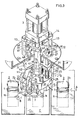
- Fig. 3 is a perspective view partly broken away and showing a heat-sealing apparatus;
- Fig. 4 is a view in vertical section showing the heat-sealing apparatus of Fig. 3; and
- Fig. 5 to Fig. 7 are views in section taken along the line V-V, line VI-VI and line VII-VII, respectively, in Fig. 4.
- Fig. 1 shows a container
main body 1 in the form of a tube of square cross section, and asquare cap 2 before the cap is attached to themain body 1. In Fig. 2, thecap 2 fitted to themain body 1 before heat sealing is shown in broken lines, and the same as heat-sealed in solid lines. Themain body 1, which is made of paper, is formed with a thermoplastic synthetic resin layer la on each of its inner and outer surfaces and has an opening at its upper end. Thecap 2, which is similarly made of paper, has analuminum foil layer 2a adhered to its rear surface. A thermoplastic synthetic resin layer 2c is further formed over the lower surface of thealuminum foil layer 2a. Thecap 2 is prepared from a square sheet of paper having thealuminum foil layer 2a and the thermoplastic synthetic resin layer 2c and formed withcutouts 2d at the four corners, by folding each side portion of the sheet in two with the front surface out to form a heat-sealing container opening edge,fittingportion 2b of upwardly projecting, inserted V-shaped cross section at each side portion of the cap. By an apparatus separate from the present apparatus, thecap 2 is placed over the opening of themain body 1, with thefitting portions 2b loosely fitted over the opening periphery of themain body 1 from above. - Figs. 3 to 7 show a heat-sealing apparatus embodying the present invention, which is disposed above a container transport conveyor C. By means of a holder H on the conveyor C, the
main body 1 having thecap 2 fitted thereto as above before heat sealing is carried,in the direction of arrow A shown to a specified position immediately below the apparatus. - The heat-sealing apparatus chiefly comprises a slide lifting
hydraulic cylinder 3, aslide 4 disposed under thepiston rod 3a of the cylinder, a verticallymovable head 5 suspended from theslide 4, a fixedpressing member 6 which is square when seen from above and provided on the' bottom side of thehead 5, a pair of divided movable pressingmembers 7 arranged around the fixedpressing member 6 and connected to thehead 5 so as to be.horizontally movable toward or away from the fixed pressingmember 6, and a heating high-frequency coil 8 attached to thehead 5 and surrounding the fixed pressingmember 6. The fixed pressingmember 6 has an outer periphery shaped to position along the inner surfaces of thefitting portions 2b of thecap 2. The movable pressingmembers 7 have an inner periphery shaped to position along the outer surfaces of thefitting portions 2b. A clearance for thefitting portions 2b to enter is formed between the fixed pressingmember 6 and the high-frequency coil 8. - The
hydraulic cylinder 3 is oriented vertically downward and supported bysupport members circular mount plate 12 fixed to a frame F and closing an aperture formed in the frame. Theslide 4 comprises a verticallymovable rod 4A extending through themount plate 12 and fixed to the lower end of thepiston rod 3a of thecylinder 3, and a verticallymovable plate 4B bolted to aflange 41 on themovable rod 4A. A pair ofopposed walls 42 positioned on each of opposite sides of therod 4A extends downward from the lower surface of themovable plate 4B. Alink 11 extending obliquely downward has an upper end positioned between theopposed walls 42 and pivoted to thewalls 42 by a horizontal pin 15 (see Fig. 5). The verticallymovable rod 4A has aguide bore 43 extending upward from its lower end and having abush 16 intimately fitted therein. Aslide rod 17 extending upright from thehead 5 is inserted into the bush from below. Theslide rod 17 has upper and lower twostepped portions flange 41, the verticallymovable rod 4A has an externally threadedportion 44 having screwed thereon alock nut 18 and an adjustingnut 19 serving also to hold the slide rod. The medium-diameter portion of theslide rod 17 is inserted through the lower end of the adjustingnut 19 which end is formed with an inward projecting 19a engaging the upper steppedportion 17a from below, whereby theslide rod 17 is prevented from slipping off from theguide bore 43. - The vertically
movable rod 17 is formed with ahole 51 extending therethrough. The small-diameter portion of theslide rod 17 is inserted through thehole 51, and the upper edge defining thehole 51 engages the lowerstepped portion 17b of therod 17 from below. Theslide rod 17 has a lower end projecting downward beyond thehead 5 and externally threaded as at 54. The fixed pressingmember 6 has acavity 55 in its bottom side and a bore communicating with the cavity and extending through themember 6. The small-diameter portion of theslide rod 17 is inserted through the bore, and anut 56 is screwed on the threadedportion 54 within thecavity 55, whereby thehead 5 and the fixedpressing member 6 are fastened together between the lowerstepped portion 17b and thenut 56. Around thehole 51, thehead 5 has a plurality ofcavities 52 formed in its lower side and bores extending therethrough and communicating with the cavities. Each ofguide rods 9 has at its lower end a small-diameter portion extending through the bore and an externally threadedportion 57 positioned within thecavity 52 and projecting from the bored portion. Withnuts 58 tightened up on the threadedportions 57 of theguide rods 9, the plurality ofguide rods 9 around theslide rod 17 are made to extend upright from thehead 5. Flanged shorttubular guide members 21 having the upper ends of theguide rods 9 slidably inserted therethrough individually are mounted on and extend through themount plate 12. The verticallymovable plate 4B is formed with bores having intermediate portions of theguide rods 9 extending therethrough and each having abush 45 intimately fitted therein. Compression springs 20 fitting around theguide rods 9 are interposed between themovable plate 4B and thehead 5. The portion of eachguide rod 9 projecting upward beyond theguide member 21 is externally threaded as at 29. An adjustingnut 22 serving also to prevent theguide rod 9 from falling off themount plate 12 by bearing on the top of theguide member 21 and alock nut 30 on thenut 22 are screwed on the threadedportion 29. - The vertically
movable head 5 is provided at each of its opposite sides with an outward projection 53 (see Fig. 6), to which intermediate portions of a pair oflevers 10 for operating the movable pressing member are pivoted byhorizontal pins 23. Opposite ends of thelever 10 are pivoted to the lower end of thelink 11 and the movable pressingmember 7 byhorizontal pins levers 10, supportlinks 28 parallel therewith connect the movable pressingmember 7 to thehead 5, whereby the movablepressing member 7 is held in a horizontal position at all times. - As shown in Fig. 7, the movable pressing
members 7 are opposed to each other with the fixed pressingmember 6 positioned therebeween. The opposed faces of themembers 7 are V-shaped when seen from above and define a square when brought toward each other. They are movable toward and away from each other in the direction of a diagonal of the square (indicated by arrow B as illustrated). This direction is at an angle of 45 degrees with the above-mentioned direction of transport of containers (arrow A). Each of the opposed inner surfaces of the movablepressing members 7 is formed at the midportion of their height with agroove 71 of U-shaped cross section. Anelastic member 26 of heat- resistant rubber or the like is fixedly fitted in thegroove 71. When the pair of pressingmembers 7 are moved toward each other, the outer periphery of the fixed pressingmember 6 is pressed on by theelastic members 26, with thefitting portions 2b of thecap 2 interposed therebetween. The heating high-frequency coil 8 is in the form of a square ring when seen from above and comprises upper and lower segments in two stages (see Fig. 6). The high-frequency coil 8 is fixed to the lower surface of thehead 5 by abracket 27 and is positioned above and below theelastic members 26 on the pair of movable pressingmembers 7 when thesemembers 7 are brought toward each other. Agroove 72 for positioning the coil free of interference is formed in.the inner surface of each movable pressingmember 7 below thegroove 71 for the elastic member. - When the container
main body 1 is sent forward to the aforesaid specified position with thefitting portions 2b of thecap 2 fitted to the opening edge of the container, thehydraulic cylinder 3 operates to project itspiston rod 3a, causing thehead 5 to descend with theslide 4 to a lower limit position, whereby thehead 5 is halted by thenuts 22 on theguide rods 9 which nuts serve as stoppers. In this state, the fixedpressing member 6 is in pressing contact with theinner surfaces 2b of the cap 2 (see Fig. 4). - When the
rod 3a further projects in this state, theslide 4 further descends and approaches thehead 5 while compressing thesprings 20 and permitting theslide rod 17 to retract into the guide bore 43. With this movement, thelinks 11 connected to theslide 4 push the upper ends of thelevers 10 outward, thereby turning thelevers 10 on thehorizontal pins 23 to move the lever lower ends inward, with the result that the pair of,movable pressingmembers 7 are moved horizontally toward each other. By this movement, theelastic members 26 on themembers 7 are pressed against the outer surfaces of thefitting portions 2b of thecap 2 in which the fixed pressingmember 6 is fitted in contact with the inner surfaces of thefitting portions 2b. As a result, thefitting portions 2b are pressed against the opening edge of the container from inside and outside. With thefitting portions 2b thus pressed on, the high-frequency coil 8 is energized for a required period of time to subject the aluminum foil to induction heating, whereby the thermoplastic synthetic resin layer 2c of thefitting portions 2b is fused to the thermoplastic synthetic resin layers la of the containermain body 1 to heat-seal the container opening edge over its opposite sides. - Usually polyethylene is used for the thermoplastic resin layers la. A composition consisting essentially of ethylene-vinyl acetate copolymer and a wax is suited for forming the thermoplastic resin layer 2c beneath the
aluminum foil layer 2a. The thermoplastic resin layer may be present on the surface to be heat-sealed of one of the container opening edge and the cap. The container main body need not always-be in the form of a square tube but can be circular or polygonal other than square, in cross section. The number of the divided fitting portions of the cap as well-as that of the divided movable pressing members is determined in accordance with the shape of the container main body.
Claims (8)
Applications Claiming Priority (2)
| Application Number | Priority Date | Filing Date | Title |
|---|---|---|---|
| JP57123941A JPS5915007A (en) | 1982-07-15 | 1982-07-15 | Method and device for heat-sealing box-shaped vessel with cap made of paper |
| JP123941/82 | 1982-07-15 |
Publications (3)
| Publication Number | Publication Date |
|---|---|
| EP0099159A2 true EP0099159A2 (en) | 1984-01-25 |
| EP0099159A3 EP0099159A3 (en) | 1985-01-30 |
| EP0099159B1 EP0099159B1 (en) | 1987-09-30 |
Family
ID=14873135
Family Applications (1)
| Application Number | Title | Priority Date | Filing Date |
|---|---|---|---|
| EP19830201035 Expired EP0099159B1 (en) | 1982-07-15 | 1983-07-13 | Method and apparatus for heatsealing |
Country Status (7)
| Country | Link |
|---|---|
| US (1) | US4504350A (en) |
| EP (1) | EP0099159B1 (en) |
| JP (1) | JPS5915007A (en) |
| AU (1) | AU561674B2 (en) |
| DE (1) | DE3373888D1 (en) |
| DK (1) | DK156209C (en) |
| NO (1) | NO157731C (en) |
Cited By (11)
| Publication number | Priority date | Publication date | Assignee | Title |
|---|---|---|---|---|
| EP0208810A1 (en) * | 1985-06-14 | 1987-01-21 | Shikoku Kakoki Co., Ltd. | Cap-heat sealing apparatus for containers |
| EP0214372A1 (en) * | 1985-07-12 | 1987-03-18 | Robert Bosch Gmbh | Apparatus for gas flushing and sealing containers |
| EP0292883A2 (en) * | 1987-05-23 | 1988-11-30 | 4P Nicolaus Kempten GmbH | Method and device for tensioning and pressing a plastic cover |
| EP0307012A1 (en) * | 1985-06-14 | 1989-03-15 | Shikoku Kakoki Co., Ltd. | Cap-heat sealing apparatus for containers |
| WO2013154908A1 (en) * | 2012-04-12 | 2013-10-17 | Sonoco Development, Inc. | Method of making a retort container |
| US8939695B2 (en) | 2011-06-16 | 2015-01-27 | Sonoco Development, Inc. | Method for applying a metal end to a container body |
| US8998027B2 (en) | 2011-09-02 | 2015-04-07 | Sonoco Development, Inc. | Retort container with thermally fused double-seamed or crimp-seamed metal end |
| US10131455B2 (en) | 2011-10-28 | 2018-11-20 | Sonoco Development, Inc. | Apparatus and method for induction sealing of conveyed workpieces |
| US10237924B2 (en) | 2013-03-15 | 2019-03-19 | Silgan Containers Llc | Temperature detection system for food container induction heating system and method |
| US10278410B2 (en) | 2014-04-24 | 2019-05-07 | Silgan Containers Llc | Food container induction heating system having power based microbial lethality monitoring |
| WO2022238357A1 (en) * | 2021-05-11 | 2022-11-17 | Société des Produits Nestlé S.A. | Food packaging produced by ultrasonic and/or induction sealing of rigid cellulose bodies and method of production thereof |
Families Citing this family (14)
| Publication number | Priority date | Publication date | Assignee | Title |
|---|---|---|---|---|
| US4755255A (en) * | 1985-06-13 | 1988-07-05 | Shikoku Kakooki Co., Ltd. | Cap heat-sealing apparatus for containers |
| US4996826A (en) * | 1988-10-07 | 1991-03-05 | Continental Can Company, Inc. | Apparatus and method for sealing a lid onto a container |
| US4941306A (en) * | 1988-10-07 | 1990-07-17 | Continental Can Company, Inc. | Apparatus and method for sealing a lid onto a container |
| US5025123A (en) * | 1988-10-07 | 1991-06-18 | Continental Can Company, Inc. | Apparatus and method for sealing a lid onto a container |
| US5499484A (en) * | 1994-02-10 | 1996-03-19 | Klearfold, Inc. | Display container |
| US6460720B1 (en) | 2000-08-03 | 2002-10-08 | Creative Foods, Llc | Container with improved lid seal and lid sealing method |
| US6571850B2 (en) | 2001-05-01 | 2003-06-03 | V-Tek Incorporated | Floating anvil useable against a heat sealing shoe |
| US6739370B2 (en) * | 2001-05-01 | 2004-05-25 | V-Tek Incorporated | Floating heated packaging shoe |
| DE50304249D1 (en) * | 2002-11-29 | 2006-08-24 | Sig Technology Ltd | DEVICE FOR SEALING A COVER ELECTOR INTO A COAT OF A COMPOSITE BODY PACKING BODY |
| GB0329487D0 (en) * | 2003-12-22 | 2004-01-28 | Le Carton Ltd | Apparatus and method for assembling enclosure assemblies |
| JP4869958B2 (en) * | 2007-01-12 | 2012-02-08 | 株式会社フジクラ | Optical transceiver and method for manufacturing the same |
| US20120255945A1 (en) * | 2011-04-05 | 2012-10-11 | Dey Subir K | Induction Seal Coil and Method |
| US9883551B2 (en) | 2013-03-15 | 2018-01-30 | Silgan Containers Llc | Induction heating system for food containers and method |
| MX2022014952A (en) | 2020-05-28 | 2023-03-08 | Sonoco Dev Inc | Systems and methods for the high-speed application of paper-based end closures on composite containers. |
Citations (4)
| Publication number | Priority date | Publication date | Assignee | Title |
|---|---|---|---|---|
| US2743859A (en) * | 1956-05-01 | Negoro | ||
| DE2527480A1 (en) * | 1975-06-20 | 1976-12-30 | Hesser Ag Maschf | Tubular container end closer and sealer - has longitudinally compact parallelogram lever system with ot sealing punch |
| FR2407063A1 (en) * | 1977-10-25 | 1979-05-25 | Akerlund & Rausing Ab | WELDING PROCESS AND DEVICE, ESPECIALLY FOR INDUCTION WELDING OF PACKAGING |
| US4264316A (en) * | 1979-06-29 | 1981-04-28 | Knudsen David S | Process for closing containers and foil membrane therefor |
Family Cites Families (9)
| Publication number | Priority date | Publication date | Assignee | Title |
|---|---|---|---|---|
| US2579775A (en) * | 1946-04-24 | 1951-12-25 | American Seal Kap Corp | Capping head |
| US2704179A (en) * | 1949-10-13 | 1955-03-15 | Oswego Falls Corp | Carton end closure |
| US3379595A (en) * | 1965-01-26 | 1968-04-23 | Mobil Oil Corp | Process and apparatus for heat sealing thermoplastic materials |
| US3549440A (en) * | 1967-10-26 | 1970-12-22 | United Glass Ltd | Method for sealing a membrane to the mouth of a container utilizing induced radio frequency current |
| JPS5485889A (en) * | 1977-12-20 | 1979-07-07 | Sumitomo Bakelite Co Ltd | Device for fabricating tightly closed vessel |
| US4237360A (en) * | 1978-11-06 | 1980-12-02 | Aluminum Company Of America | Induction heat sealing |
| US4301640A (en) * | 1979-11-09 | 1981-11-24 | Brown Company | Container closing means and process |
| US4344814A (en) * | 1979-12-28 | 1982-08-17 | Champion International Corporation | Apparatus for heat sealing round containers |
| US4305771A (en) * | 1979-12-28 | 1981-12-15 | Champion International Corporation | Method for heat sealing round containers |
-
1982
- 1982-07-15 JP JP57123941A patent/JPS5915007A/en active Granted
-
1983
- 1983-07-12 AU AU16763/83A patent/AU561674B2/en not_active Ceased
- 1983-07-13 EP EP19830201035 patent/EP0099159B1/en not_active Expired
- 1983-07-13 DE DE8383201035T patent/DE3373888D1/en not_active Expired
- 1983-07-14 DK DK324783A patent/DK156209C/en not_active IP Right Cessation
- 1983-07-14 NO NO832568A patent/NO157731C/en unknown
- 1983-07-15 US US06/514,235 patent/US4504350A/en not_active Expired - Fee Related
Patent Citations (4)
| Publication number | Priority date | Publication date | Assignee | Title |
|---|---|---|---|---|
| US2743859A (en) * | 1956-05-01 | Negoro | ||
| DE2527480A1 (en) * | 1975-06-20 | 1976-12-30 | Hesser Ag Maschf | Tubular container end closer and sealer - has longitudinally compact parallelogram lever system with ot sealing punch |
| FR2407063A1 (en) * | 1977-10-25 | 1979-05-25 | Akerlund & Rausing Ab | WELDING PROCESS AND DEVICE, ESPECIALLY FOR INDUCTION WELDING OF PACKAGING |
| US4264316A (en) * | 1979-06-29 | 1981-04-28 | Knudsen David S | Process for closing containers and foil membrane therefor |
Cited By (20)
| Publication number | Priority date | Publication date | Assignee | Title |
|---|---|---|---|---|
| EP0208810A1 (en) * | 1985-06-14 | 1987-01-21 | Shikoku Kakoki Co., Ltd. | Cap-heat sealing apparatus for containers |
| EP0307012A1 (en) * | 1985-06-14 | 1989-03-15 | Shikoku Kakoki Co., Ltd. | Cap-heat sealing apparatus for containers |
| EP0214372A1 (en) * | 1985-07-12 | 1987-03-18 | Robert Bosch Gmbh | Apparatus for gas flushing and sealing containers |
| EP0292883A2 (en) * | 1987-05-23 | 1988-11-30 | 4P Nicolaus Kempten GmbH | Method and device for tensioning and pressing a plastic cover |
| EP0292883A3 (en) * | 1987-05-23 | 1990-01-10 | 4P Nicolaus Kempten GmbH | Method and device for tensioning and pressing a plastic cover |
| US8939695B2 (en) | 2011-06-16 | 2015-01-27 | Sonoco Development, Inc. | Method for applying a metal end to a container body |
| US10259612B2 (en) | 2011-09-02 | 2019-04-16 | Sonoco Development, Inc. | Container with thermally fused double-seamed or crimp-seamed metal end |
| US8998027B2 (en) | 2011-09-02 | 2015-04-07 | Sonoco Development, Inc. | Retort container with thermally fused double-seamed or crimp-seamed metal end |
| US9499299B2 (en) | 2011-09-02 | 2016-11-22 | Sonoco Development, Inc. | Container with thermally fused double-seamed or crimp-seamed metal end |
| US9783337B2 (en) | 2011-09-02 | 2017-10-10 | Sonoco Development, Inc. | Container with thermally fused double-seamed or crimp-seamed metal end |
| US9988179B2 (en) | 2011-09-02 | 2018-06-05 | Sonoco Development, Inc. | Container with thermally fused double-seamed or crimp-seamed metal end |
| US10994888B2 (en) | 2011-09-02 | 2021-05-04 | Sonoco Development, Inc. | Container with thermally fused double-seamed or crimp-seamed metal end |
| US10131455B2 (en) | 2011-10-28 | 2018-11-20 | Sonoco Development, Inc. | Apparatus and method for induction sealing of conveyed workpieces |
| WO2013154908A1 (en) * | 2012-04-12 | 2013-10-17 | Sonoco Development, Inc. | Method of making a retort container |
| US10399139B2 (en) | 2012-04-12 | 2019-09-03 | Sonoco Development, Inc. | Method of making a retort container |
| US10569324B2 (en) | 2012-04-12 | 2020-02-25 | Sonoco Development, Inc. | Method of making a retort container |
| US11040495B2 (en) | 2012-04-12 | 2021-06-22 | Sonoco Development, Inc | Method of making a retort container |
| US10237924B2 (en) | 2013-03-15 | 2019-03-19 | Silgan Containers Llc | Temperature detection system for food container induction heating system and method |
| US10278410B2 (en) | 2014-04-24 | 2019-05-07 | Silgan Containers Llc | Food container induction heating system having power based microbial lethality monitoring |
| WO2022238357A1 (en) * | 2021-05-11 | 2022-11-17 | Société des Produits Nestlé S.A. | Food packaging produced by ultrasonic and/or induction sealing of rigid cellulose bodies and method of production thereof |
Also Published As
| Publication number | Publication date |
|---|---|
| JPS6218405B2 (en) | 1987-04-22 |
| NO157731C (en) | 1988-05-11 |
| NO157731B (en) | 1988-02-01 |
| EP0099159A3 (en) | 1985-01-30 |
| AU1676383A (en) | 1984-01-19 |
| AU561674B2 (en) | 1987-05-14 |
| DK156209C (en) | 1989-12-04 |
| EP0099159B1 (en) | 1987-09-30 |
| DK324783D0 (en) | 1983-07-14 |
| DK324783A (en) | 1984-01-16 |
| NO832568L (en) | 1984-01-16 |
| JPS5915007A (en) | 1984-01-26 |
| DK156209B (en) | 1989-07-10 |
| US4504350A (en) | 1985-03-12 |
| DE3373888D1 (en) | 1987-11-05 |
Similar Documents
| Publication | Publication Date | Title |
|---|---|---|
| EP0099159A2 (en) | Method and apparatus for heatsealing | |
| EP0032820B1 (en) | Method and apparatus for producing a sterilised package with a product, and the package produced | |
| US4707213A (en) | Induction heating unit for heat bonding a lid having a metallic layer to a container | |
| US5371996A (en) | Apparatus for sealing containers | |
| US5819507A (en) | Method of filling a packaging container | |
| US3519158A (en) | Aseptic connector and closure | |
| EP0965438A2 (en) | Apparatus for bonding pour spout to containers | |
| US2857083A (en) | Combination jar lid and measuring cup | |
| US5819504A (en) | Process and apparatus for applying fitments to a carton | |
| US3868917A (en) | Sealed container and apparatus for and method of sealing same | |
| NO871563D0 (en) | DEVICE FOR PACKAGING MACHINE. | |
| EP0559290B1 (en) | Apparatus for sealing containers | |
| US3291361A (en) | Container rim formation | |
| US3752387A (en) | Sealed container | |
| US3882661A (en) | Apparatus for bending the edge of a foil around the edge of a tray | |
| US6250543B1 (en) | Container of gabled roof type having top seal rib and top sealing device therefor | |
| EP0024408B1 (en) | A lid mounting apparatus | |
| GB2135957A (en) | Temporarily fastening down a pail handle | |
| US4005975A (en) | Apparatus for connecting together parts of foam plastics | |
| US3122262A (en) | Sealing closure and method and apparatus for forming same | |
| CN116495291B (en) | Plastic film upset heat sealing device | |
| EP0315237A1 (en) | A method and an arrangement for the application of an end plate to a packing container body | |
| SU1479349A1 (en) | Device for packing products into heat-sealabde bags | |
| JPS6127252B2 (en) | ||
| JPH04201319A (en) | Device and method for molding vessel |
Legal Events
| Date | Code | Title | Description |
|---|---|---|---|
| PUAI | Public reference made under article 153(3) epc to a published international application that has entered the european phase |
Free format text: ORIGINAL CODE: 0009012 |
|
| AK | Designated contracting states |
Designated state(s): DE FR GB NL SE |
|
| PUAL | Search report despatched |
Free format text: ORIGINAL CODE: 0009013 |
|
| AK | Designated contracting states |
Designated state(s): DE FR GB NL SE |
|
| 17P | Request for examination filed |
Effective date: 19850410 |
|
| GRAA | (expected) grant |
Free format text: ORIGINAL CODE: 0009210 |
|
| AK | Designated contracting states |
Kind code of ref document: B1 Designated state(s): DE FR GB NL SE |
|
| REF | Corresponds to: |
Ref document number: 3373888 Country of ref document: DE Date of ref document: 19871105 |
|
| ET | Fr: translation filed | ||
| PLBE | No opposition filed within time limit |
Free format text: ORIGINAL CODE: 0009261 |
|
| STAA | Information on the status of an ep patent application or granted ep patent |
Free format text: STATUS: NO OPPOSITION FILED WITHIN TIME LIMIT |
|
| 26N | No opposition filed | ||
| PGFP | Annual fee paid to national office [announced via postgrant information from national office to epo] |
Ref country code: GB Payment date: 19940520 Year of fee payment: 12 |
|
| PGFP | Annual fee paid to national office [announced via postgrant information from national office to epo] |
Ref country code: SE Payment date: 19940620 Year of fee payment: 12 |
|
| PGFP | Annual fee paid to national office [announced via postgrant information from national office to epo] |
Ref country code: FR Payment date: 19940718 Year of fee payment: 12 |
|
| PGFP | Annual fee paid to national office [announced via postgrant information from national office to epo] |
Ref country code: NL Payment date: 19940731 Year of fee payment: 12 |
|
| PGFP | Annual fee paid to national office [announced via postgrant information from national office to epo] |
Ref country code: DE Payment date: 19940817 Year of fee payment: 12 |
|
| EAL | Se: european patent in force in sweden |
Ref document number: 83201035.9 |
|
| PG25 | Lapsed in a contracting state [announced via postgrant information from national office to epo] |
Ref country code: GB Effective date: 19950713 |
|
| PG25 | Lapsed in a contracting state [announced via postgrant information from national office to epo] |
Ref country code: SE Effective date: 19950714 |
|
| PG25 | Lapsed in a contracting state [announced via postgrant information from national office to epo] |
Ref country code: NL Effective date: 19960201 |
|
| GBPC | Gb: european patent ceased through non-payment of renewal fee |
Effective date: 19950713 |
|
| NLV4 | Nl: lapsed or anulled due to non-payment of the annual fee |
Effective date: 19960201 |
|
| EUG | Se: european patent has lapsed |
Ref document number: 83201035.9 |
|
| PG25 | Lapsed in a contracting state [announced via postgrant information from national office to epo] |
Ref country code: FR Effective date: 19960430 |
|
| PG25 | Lapsed in a contracting state [announced via postgrant information from national office to epo] |
Ref country code: DE Effective date: 19960501 |
|
| REG | Reference to a national code |
Ref country code: FR Ref legal event code: ST |
|
| REG | Reference to a national code |
Ref country code: FR Ref legal event code: ST |
|
| REG | Reference to a national code |
Ref country code: FR Ref legal event code: ST |