EP0098293B1 - Tragestruktur für antenne - Google Patents
Tragestruktur für antenne Download PDFInfo
- Publication number
- EP0098293B1 EP0098293B1 EP83900510A EP83900510A EP0098293B1 EP 0098293 B1 EP0098293 B1 EP 0098293B1 EP 83900510 A EP83900510 A EP 83900510A EP 83900510 A EP83900510 A EP 83900510A EP 0098293 B1 EP0098293 B1 EP 0098293B1
- Authority
- EP
- European Patent Office
- Prior art keywords
- bearing
- support
- base
- flanges
- flange
- Prior art date
- Legal status (The legal status is an assumption and is not a legal conclusion. Google has not performed a legal analysis and makes no representation as to the accuracy of the status listed.)
- Expired
Links
- 230000008878 coupling Effects 0.000 claims description 52
- 238000010168 coupling process Methods 0.000 claims description 52
- 238000005859 coupling reaction Methods 0.000 claims description 52
- 230000000712 assembly Effects 0.000 description 7
- 238000000429 assembly Methods 0.000 description 7
- 229910052751 metal Inorganic materials 0.000 description 7
- 239000002184 metal Substances 0.000 description 7
- 239000000463 material Substances 0.000 description 4
- 239000007787 solid Substances 0.000 description 4
- 230000008859 change Effects 0.000 description 3
- 230000002441 reversible effect Effects 0.000 description 2
- 229910000831 Steel Inorganic materials 0.000 description 1
- 239000004809 Teflon Substances 0.000 description 1
- 229920006362 Teflon® Polymers 0.000 description 1
- 230000009471 action Effects 0.000 description 1
- 230000001154 acute effect Effects 0.000 description 1
- 229910052782 aluminium Inorganic materials 0.000 description 1
- XAGFODPZIPBFFR-UHFFFAOYSA-N aluminium Chemical compound [Al] XAGFODPZIPBFFR-UHFFFAOYSA-N 0.000 description 1
- 238000005452 bending Methods 0.000 description 1
- 230000006835 compression Effects 0.000 description 1
- 238000007906 compression Methods 0.000 description 1
- 238000010276 construction Methods 0.000 description 1
- 239000004519 grease Substances 0.000 description 1
- 230000000977 initiatory effect Effects 0.000 description 1
- 238000009434 installation Methods 0.000 description 1
- 230000001050 lubricating effect Effects 0.000 description 1
- 230000013011 mating Effects 0.000 description 1
- 230000007246 mechanism Effects 0.000 description 1
- 238000000034 method Methods 0.000 description 1
- 230000000737 periodic effect Effects 0.000 description 1
- 230000003014 reinforcing effect Effects 0.000 description 1
- 230000006641 stabilisation Effects 0.000 description 1
- 238000011105 stabilization Methods 0.000 description 1
- 230000000087 stabilizing effect Effects 0.000 description 1
- 239000010959 steel Substances 0.000 description 1
- 238000003466 welding Methods 0.000 description 1
Images

Classifications
-
- H—ELECTRICITY
- H01—ELECTRIC ELEMENTS
- H01Q—ANTENNAS, i.e. RADIO AERIALS
- H01Q3/00—Arrangements for changing or varying the orientation or the shape of the directional pattern of the waves radiated from an antenna or antenna system
- H01Q3/02—Arrangements for changing or varying the orientation or the shape of the directional pattern of the waves radiated from an antenna or antenna system using mechanical movement of antenna or antenna system as a whole
- H01Q3/08—Arrangements for changing or varying the orientation or the shape of the directional pattern of the waves radiated from an antenna or antenna system using mechanical movement of antenna or antenna system as a whole for varying two co-ordinates of the orientation
-
- H—ELECTRICITY
- H01—ELECTRIC ELEMENTS
- H01Q—ANTENNAS, i.e. RADIO AERIALS
- H01Q1/00—Details of, or arrangements associated with, antennas
- H01Q1/12—Supports; Mounting means
- H01Q1/125—Means for positioning
Definitions
- the present invention relates to bearing structures for facilitating rotational movement between adjacent members, and more particularly relates to a bearing assembly for selectively permitting rotation of an antenna reflector about an axis.
- an antenna reflector In the field of satellite communications, a growing need has arisen for earth station antennas that are inexpensive to construct and easy to operate in order to change the orientation of the reflector to aim at any one of a number of geosynchronous satellites. In order to permit changes in its orientation, an antenna reflector must pivot or rotate about one or more axes, depending on the type of mounting utilized.
- One typical antenna mounting structure is the elevation-over-azimuth type, in which bearing structures must be provided for independent rotation about the vertical or azimuth axis and about the horizontal or elevation axis.
- the elevation axis assembly should allow the reflector to be pointed from slightly below the horizon to high. above the horizon.
- the azimuth bearing assembly has utility proportional to the degree of rotation permitted; optimal utility is realized if the reflector can rotate 360° about the azimuth axis.
- Some typical azimuth bearings provide such flexibility, and some do not.
- the reflector is attached to a vertical rod rotatably mounted on bearings extending from a support structure. Rotation through 360° is not possible, because the reflector cannot swing past the mounting structure in typical installations. Also, the support structure must be relatively massive in order to provide stability.
- Rotation through 360° and stability has been provided by another typical azimuth bearing system, in which the antenna reflector is mounted on a large circular bearing, such as a roller bearing 2-10 feed in diameter, and the bearing is carried in a circular race. Stability is gained by increasing the diameter of the circular bearing, which also steeply increases the cost of this type of azimuth bearing system.
- the polar reflector mounting structure is a widely used alternative to the elevation-over-azimuth system.
- an antenna reflector can move from one satellite to another by rotation about a single axis slanted with respect to the horizon and oriented in the North-South plane.
- the azimuth position of such an antenna must be initially fixed to place the polar axis in the North-South plane, and therefore it is best to provide an azimuth bearing assembly to facilitate fine adjustment of the azimuth position after the base of the antenna mounting structure is secured to a foundation.
- An elevation assembly is required to permit additional precise adjustment of the slant of the polar axis.
- bearing assemblies associated with antenna mounting structures must have means for locking the position of the antenna about the various axes.
- the pointing accuracy of an antenna aimed at a satellite must be within about 0.1-0.25°.
- convenient and accurate positioning of an antenna requires that the bearing assemblies be lockable without motion of the antenna during the locking procedure.
- such structures have generally been constructed of heavy duty materials, often including expensive precision bearings.
- the mounting structure providing the required precision adjustments has become more acute.
- an antenna mounting apparatus including a bearing structure for per- .mitting rotation of said antenna about an axis, characterized by:
- a bearing structure embodying the present invention can be used for selectively permitting rotation about any axis of rotation needed to orient the antenna reflector, including the azimuth axis, the elevation axis, and the polar axis.
- Bearing structures as generally described above can be adapted along or in pairs to provide stable bearing assemblies.
- the concept of the present invention is not limited to antenna mounting structures, but also can be embodied in a bearing structure for permitting relative rotation about an axis between a pair of adjacent members, comprising radially outwardly extending circular flanges defined by each of the members, the flanges being positioned coaxially about the axis and adjacent to one another; annular coupling means surrounding the flanges and retaining the flanges adjacent to one another, the coupling defining an annular inwardly opening recess therein for receiving the flanges; and shaft means extending axially from the center of one of the members to be rotatably received within an axial bore defined by the other of the members, the shaft means and bore maintaining axial alignment of the members. Locking and.releasing of the bearing can be accomplished by contracting or expanding the circumference of the coupling means, such as by dividing the coupling means into two parts, and attaching the ends of the parts together with bolts that can be tightened or loosened.
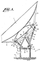
- Fig. 1 shows an antenna mounting structure 10 of the polar type, embodying the present invention.
- An antenna reflector 11 is shown-supported by the mounting structure 10.
- the construction of the antenna 11 and the electronics associated therewith form no part of the present invention, and therefore are not shown in detail.
- the mounting structure for the reflector 11 includes a base 12 securely anchored to the earth or a platform 13. Where convenient, the base 12 may be embedded in concrete. In the preferred embodiment shown, the base 12 comprises a cylinder of sheet metal. Strength and stability of the antenna mounting structure 10 is provided by the inherent resistance of the cylindrical shape to bending or tipping under the influence of the weight of the antenna or exterior forces such as wind.
- a cupola 14 Positioned to rest upon the base 12 is a cupola 14 which preferably comprises sheet metal formed in the shape of a cone, although the support function of the cupola 14 can be provided by other structural shapes. As shown, the cupola 14 is assembled from two halves. Outwardly extending flanges 15 facilitate connection of the halves of the cupola 14 and lend rigidity to the cupola in the plane of the polar axis.
- the cupola carries a polar support assembly 16 which directly supports the reflector 11, and is described in detail hereinafter.
- the primary connection of the polar support assembly 16 to the cupola 14 is by way of a bracket 17 situated at the top of the cupola 14, and a bolt 18 which forms an elevation pivot for initial adjustment of the elevation of the reflector 11.
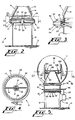
- the cupola 14 is joined to the base 12 by an azimuth bearing 20 shown in Figs. 1, 2 and 3.
- the azimuth bearing 20 includes a base bearing projection 21 which extends upwardly and terminates in a circular radially outwardly extending base bearing flange 22.
- the base bearing projection 21 is, in the preferred embodiment, merely an extension of the cylinder of sheet metal forming the base 12. However, it will be understood that- the general shape of the base could be other than cylindrical, in which case a distinct projection extending away from the base to define the base bearing flange might be necessary.
- the sheet metal of the base bearing projection 21 is formed into the base bearing flange 22 as shown in Figs. 2 and 3.
- the flange 22 has a cross-sectional shape of an inwardly opening truncated "V". There are thus defined an upper flange-receiving surface 23 that slopes downwardly with increasing radius, and a lower coupling-receiving surface 24 that slopes upwardly with increasing radius.
- the cupola 14 terminates in a downwardly extending cupola bearing projection 25 which defines at its end a circular radially outwardly extending cupola bearing flange 26.
- the lower surface of the flange 26 is a flange-engaging surface 27 which slopes downwardly with increasing radius and is supported by the mating flange-receiving surface 23 of the base bearing flange 22.
- a layer of lubricating material such as grease or Teflon, may be applied to the -base flange-receiving surface 23, as shown in Fig. 3, or to the cupola flange-engaging surface 27.
- the base bearing flange 22 can be extended inwardly and upwardly, as shown in Fig. 3, to form a sleeve 35 to matingly receive the cupola 14.
- the sleeve 35 provides lateral stability without adding the more detailed stabilizing means described below.
- the cupola bearing flange 26 and the base bearing flange 22 are held togather by a circular coupling 29 surrounding the flanges.
- the coupling has a cross-sectional shape of a truncated "V", and defines an inwardly opening annular recess 32 for receiving the flanges 22 and 26.
- the coupling 29 can be urged inwardly onto the engaged flanges to lock the flanges, and alternately released to allow relative movement thereof, by effectively contracting or expanding the circumference of the coupling. In the embodiment shown, this is done by providing at least one break in the circumference of the coupling 29, and outwardly extending clamping flanges 30 at the adjacent ends of the coupling 29.
- a bolt and nut assembly 31 passes through the flanges 30 and can be tightened or loosened tojock or unlock the bearing 20.
- the coupling 29 also preferably includes annular flanges 33 and 34 extending upwardly and downwardly, respectively, from the inward ends of the coupling 29.
- the flanges 33 and 34 provide strength and rigidity to the coupling 29.
- a brace 36 extends across the throat of the cupola bearing projection 25 to strengthen the sheet metal cupola 14.
- a pair of brackets 37 suspend from the brace 36 a shaft support block 38 and a depending shaft 39 which extends axially from the center of the cupola bearing projection 25 downwardly beyond the height of the base bearing flange 22.
- the shaft 39 is preferably constructed of steel.
- the base 12 includes an aluminum plate 40 defining a bore 41 therein supported by a diaphragm 43 which spans the base bearing projection 21.
- the bore 41 is positioned to receive the shaft 39, such that the shaft 39 and plate 40 assist in centering the cupola 14 with respect to the coaxial base 12. It should be understood, however, that the bearing 20 is operable without the location means provided by the shaft 39.
- the bolt and nut assembly 31 In operation of the bearing 20, the bolt and nut assembly 31 is loosened to permit relative rotation of the cupola 14 and base 12.
- the shaft 39 and plate 40 assist in maintaining alignment of the cupola and base during relative rotation.
- the bolt and nut assembly 31 is tightened.
- the coupling 29 is thereby contracted radially inwardly, the action of the coupling 29 upon the flanges 22 and 26 is to compress the flanges axially against one another.
- the locking operation initially locks the flanges against one another so that the desired azimuth orientation cannot change as a result of mechanical manipulation of the locking mechanism.
- bearing structure just described has applicability to many types of adjacent members that require a bearing for relative rotational movement. If such members can be provided with adjacent radially outwardly extending flanges around which can be placed a coupling having an inwardly opening recess for receiving and clamping the flanges, a bearing structure embodying the present invention can be provided.
- the broad concept of the present invention is not restricted to bearing structures for antenna mounting systems.
- the antenna mounting structure 10 includes a polar support assembly 16 supported by the cupola 14.
- a polar support beam 46 is formed from a downwardly opening channel section, and is pivotally supported intermediate its ends by the bolt 18which passes through the bracket 17 of the cupola 14.
- the polar support beam 46 is stabilized and maintained in a particular orientation by four telescoping support braces, two of which are shown in Fig. 1.
- a pair of support braces 48 are affixed at their lower ends to the cupola 14 by bolts 50, and are affixed at their upper ends to the polar support beam 46 by bolts 51.
- the telescoping support braces 48 can comprise nesting channel sections that can be slid relative to one another to lengthen or shorten the length of the braces 48, and then locked by tightening a lock bolt 52, in a manner well known to those skilled in the art.
- a second pair of telescopic support braces 49 are attached at their lower ends to the cupola 14 by bolts 54 and to the polar support beam 46 at their upper ends by bolts 55.
- the braces 49 are similarly nesting channel sections that can be locked at the desired length by a lock bolt 53.
- brackets 58 and 59 are attached by bolts 60 and 61, respectively, to the support beam 46.
- One arm of each bracket is thus fixed to the support beam 46.
- the other arm of each bracket extends away from the cupola 14 and defines an opening therein (not shown) for receiving bolt and nut assemblies 63 and 64, respectively.
- the polar rotational axis provided by the polar support assembly 16 is defined by a line through the bolt and nut assemblies 63 and 64, and is shown as a dashed line 65 in Fig. 1.
- Antenna support legs 67 and 68 are provided and define openings (not shown) adjacent to one end thereof.
- the legs 67 and 68 are positioned adjacent to the brackets 58 and 59 by passing the bolt assemblies 63 and 64 through the openings in the legs 67 and 68.
- the legs 67 and 68 are attached to a central antenna base 70 which is a dome-shaped structural member enclosed by a bottom member 71.
- the central antenna base 70 can be constructed of sheet metal.
- the antenna reflector 11 is generally constructed of panels (details of which are not shown) which are fixed at their inner ends to the central antenna base 70.
- a plurality of braces 74 extend from the outer circumference of the central antenna base 70 toward the periphery of the reflector 11.
- the member 72 extends outside the braces 48 and provides an hour-angle actuator. The position at which the bolts 50 attach the lower ends of the braces 48 to the cupola 14 can be modified to permit a greater range of movement by the actuator 72.
- Operation of the polar support assembly 16 requires an initial elevation adjustment and periodic adjustments about the polar axis 65.
- the telescoping support braces 48 and 49 are adjusted to place the polar axis 65 at the proper angle with respect to the horizon so that rotation of the antenna about the polar axis will intercept the positions of a series of geosynchronous satellites.
- the angle of elevation is typically approximately equal to the latitude at which the antenna is located.
- the lock bolts 52 and 53 are tightened to maintain the proper angle of elevation.
- the bolt and nut assemblies 63 and 64 are loosened, and the antenna reflector is rotated about the polar axis 65 to the desired orientation by adjusting the length of the telescoping member 72. Then the bolts 63 and 64 are tightened to lock the antenna in position aiming at the desired satellite.
- FIG. 5 A second embodiment of the present invention in an antenna mounting structure 80 is shown in Figs. 5 and 6.
- the structure 80 includes a cylindrical base 12 and a cupola 14' suitably shaped to support shaft 99.
- the structure 80 further includes a cylindrical drive section 82 which is mounted between the base 12 and cupola 14.
- the drive section 82 includes an annular rack gear 83 extending from the outer circumference of the drive section 82.
- the rack gear 83 can be integrally cast with the drive section 82 or can be attached thereto by a suitable means such as welding.
- the drive section 82 is connected to the base 12 by means of a bearing 85 constructed according to the invention, similar to the bearing 20 shown in Fig. 1.
- the bearing 85 includes a modified bolt assembly 87 for connecting the ends of the coupling of the bearing 85.
- the bolt assembly 87 extends through the clamping flanges 30, but includes a compression spring 88 between one of the clamping flanges and a retaining nut 89.
- the strength of the spring 88 is such that under normal conditions the coupling of the bearing 85 engages the flanges of the bearing with sufficient force to lock the drive section 82 and base 12 in desired relative positions. However, mechanical force applied to rotate the drive section 82 can overcome the force of the spring 88 without loosening the bolt assembly 87.
- the drive section 82 is provided with an upper bearing flange so that it can be connected to the cupola 14' by a bearing 91 that is identical to the bearing 20 shown in Fig. 1.
- the coupling of the bearing 91 is generally left in a tightened condition to lock the cupola 14' to the drive section 82 so that the cupola 14' and antenna reflector 11 will rotate with the drive section 82.
- a motor 93 is mounted on the base 12 by means of a conventional motor mount 94.
- a drive shaft 95 of the motor 93 extends upwardly beyond the bearing 85 and has a pinion gear 96 mounted horizontally to the end of the drive shaft 95 in engagement with the rack gear 83.
- the motor 93 can be a conventional electric or hydraulic reversible or non-reversible motor, provided with conventional controls for causing the motor 93 to rotate the pinion gear 96 and therefore rotate the drive section 82 and antenna about the azimuth axis as desired. It will be further understood that a variable speed drive can be utilized to permit rotation of the antenna in very small increments.
- the antenna mounting structure 80 of Fig. 5 also includes an elevation axis assembly 98.
- Support means for the elevation axis assembly 98 is provided by the base 12, the drive section 82, the cupola 14' and a horizontal cylindrical cross member 99 attached to the top of the cupola 14'.
- Bearing flanges 100 and 101 similar to the base bearing flange 22 of Fig. 2 are provided at the opposite ends of the cross piece 99, as shown in Fig. 6.
- Bearings 108 and 109 identical to the bearing 20 of Fig. 1 connectthe cross piece 99 to an antenna support framework which includes frame bearing segments 102 and 103 which define bearing projections extending toward the cross piece 99 and terminate in bearing flanges 104 and 105.
- the flanges 104 and 105 engage the bearing flanges 100 and 101 of the cross piece 99.
- Annular couplings 110 and 111 receive and selectively lock the adjacent flanges 100 and 104, in the bearing 108, and adjacent flanges 101 and 105, in the bearing 109.
- Each coupling 108 and 109 includes clamping flanges 30 and a bolt and nut assembly for tightening the coupling similar to those described earlier in connection with the bearing 20.
- the bearings 108 and 109 are unlocked by loosening the couplings 110 and 111.
- the antenna is thereafter rotated about the elevation axis which passes through the centers of the bearings 108 and 109 until the desired orientation is obtained. Then, the couplings 110 and 111 are tightened to lock the antenna in its new orientation.
- mechanical means can be provided for remote changing of the orientation of the antenna about the elevation axis. Such mechanical means could be similar to the motor 93 and driving gears 83 and 96 described hereinabove for causing rotation about the azimuth axis.
- a polar axis assembly could be con- .structed with a pair of bearing structures according to the invention in a manner similar to the elevation axis assembly 98.
- a third embodiment of the present invention in an antenna mounting structure 115 is shown in Fig. 7.
- a single bearing structure is utilized to provide an elevation axis.
- the base 12 is connected by the bearing 20 to a specially constructed cupola 117 which includes a vertically extending neck 118 and a cupola bearing projection 119 which extends horizontally and defines at its end a bearing flange (not shown).
- An antenna support frame 120 is connected to the antenna reflector 11 by a plurality of braces 121.
- the support frame 120 includes a cylindrical bearing projection 122 which also defines a bearing flange that engages the bearing flange of the cupola projection 119 and is received by a coupling in a bearing structure 123 identical to the bearing 20, 108 and 109. Operation of the bearing 123 to pivot the reflector 11 about the elevation axis will be apparent from the description of previous embodiments.
- Fig. 8 shows a bearing structure 125 which includes a base 126 which defines a solid triangular bearing flange 127.
- An adjacent member or cupola 129 extends downwardly and defines a circular bearing flange 130 which engages the base bearing flange 127.
- a coupling 132 is provided having the shape of a simple "V", without reinforcing flanges or truncation of the point of the "V".
- Fig. 9 shows another embodiment of a bearing structure 134 in which a base 135 defines a triangular base bearing flange 136 which has a horizontal flange engaging surface.
- a cupola 137 defines a cupola bearing flange 138 that is the mirror image of the base bearing flange 136.
- a coupling 140 receives and locks the flanges 136 and 138.
- the flange shapes shown in Fig. 9 are embodied in solid adjacent members, a base 143 and a cupola 147.
- the solid cylindrical base 143 defines an annular base bearing flange 144 having a flat horizontal upper surface extending across the base 143.
- the base 143 also defines an axial bore 145.
- the solid cylindrical cupola 147 defines a cupola bearing flange 148 having a flat horizontal lower surface.
- An integrally formed shaft projection 149 extends into the bore 145 to provide a function similar to that of the shaft 39 of the embodiment shown in Fig. 2.
- a coupling 150 surrounds and receives the bearing flanges 144 and 148.
- each provide at least one bearing flange including a flange receiving sur- .face and a coupling receiving surface which are angled with respect to one another so as to define a "V", the arms of which diverge toward the axis of rotation.
- the coupling-receiving surfaces of the adjacent flanges are angled with respect to one another such that the inwardly opening annular recess of the coupling engages said surfaces, when the coupling is urged radially inwardly, in a manner which urges the adjacent flanges axially toward one another.
- the present invention provides a strong, lightweight, inexpensive, lockable bearing apparatus for selectively permitting rotation between two adjacent members.
- the bearing structure according to the invention is particularly useful in providing axes of rotation in antenna mounting structures.
Landscapes
- Support Of Aerials (AREA)
- Variable-Direction Aerials And Aerial Arrays (AREA)
- Details Of Aerials (AREA)
- Sliding-Contact Bearings (AREA)
- Input Circuits Of Receivers And Coupling Of Receivers And Audio Equipment (AREA)
Claims (11)
Priority Applications (1)
| Application Number | Priority Date | Filing Date | Title |
|---|---|---|---|
| AT83900510T ATE26770T1 (de) | 1982-01-13 | 1983-01-10 | Tragestruktur fuer antenne. |
Applications Claiming Priority (2)
| Application Number | Priority Date | Filing Date | Title |
|---|---|---|---|
| US06/339,124 US4475110A (en) | 1982-01-13 | 1982-01-13 | Bearing structure for antenna |
| US339124 | 1982-01-13 |
Publications (3)
| Publication Number | Publication Date |
|---|---|
| EP0098293A1 EP0098293A1 (de) | 1984-01-18 |
| EP0098293A4 EP0098293A4 (de) | 1984-05-17 |
| EP0098293B1 true EP0098293B1 (de) | 1987-04-22 |
Family
ID=23327602
Family Applications (1)
| Application Number | Title | Priority Date | Filing Date |
|---|---|---|---|
| EP83900510A Expired EP0098293B1 (de) | 1982-01-13 | 1983-01-10 | Tragestruktur für antenne |
Country Status (7)
| Country | Link |
|---|---|
| US (1) | US4475110A (de) |
| EP (1) | EP0098293B1 (de) |
| AU (1) | AU556985B2 (de) |
| CA (1) | CA1203895A (de) |
| DE (1) | DE3371142D1 (de) |
| NO (1) | NO833253L (de) |
| WO (1) | WO1983002530A1 (de) |
Families Citing this family (20)
| Publication number | Priority date | Publication date | Assignee | Title |
|---|---|---|---|---|
| US4598297A (en) * | 1983-10-21 | 1986-07-01 | Hawkins Joel W | Mounting apparatus for satellite dish antennas |
| US4628323A (en) * | 1983-11-01 | 1986-12-09 | Crean Robert F | Simplified polar mount for satellite tracking antenna |
| US4563687A (en) * | 1984-02-06 | 1986-01-07 | Gte Communications Products Corporation | Adjustable antenna mount |
| US4626864A (en) * | 1984-03-12 | 1986-12-02 | Polarmax Corporation | Motorized antenna mount for satellite dish |
| US4652890A (en) * | 1984-07-24 | 1987-03-24 | Crean Robert F | High rigidity, low center of gravity polar mount for dish type antenna |
| US4689635A (en) * | 1984-08-06 | 1987-08-25 | Allegretti & Company | Apparatus for orientating TV antennas for satellite reception |
| US4617572A (en) * | 1984-08-14 | 1986-10-14 | Albert Hugo | Television dish antenna mounting structure |
| US4691207A (en) * | 1984-09-04 | 1987-09-01 | Nissho Iwai American Corporation | Antenna positioning apparatus |
| US4644365A (en) * | 1985-02-08 | 1987-02-17 | Horning Leonard A | Adjustable antenna mount for parabolic antennas |
| US4654670A (en) * | 1985-02-27 | 1987-03-31 | Tracker Mounts Inc. | Tracker mount assembly for microwave dishes |
| US4698640A (en) * | 1985-08-08 | 1987-10-06 | Gte Sprint Communications Corp | Adjustable platform mounteed horn antenna |
| FR2608846B1 (fr) * | 1986-12-18 | 1989-03-24 | Alcatel Thomson Faisceaux | Antenne de telecommunications a reflecteur |
| EP0470799B1 (de) * | 1990-08-06 | 1995-10-11 | Texas Instruments Incorporated | System und Verfahren zum Stützen und Drehen eines Bildschirms |
| US5281975A (en) * | 1991-10-03 | 1994-01-25 | J.G.S. Engineering Inc. | Base support for movable antenna |
| US5473335A (en) * | 1994-01-11 | 1995-12-05 | Tines; John L. | Base support for movable antenna |
| US5633647A (en) * | 1994-01-11 | 1997-05-27 | Tines; John L. | Base support for movable antenna |
| US5579018A (en) * | 1995-05-11 | 1996-11-26 | Space Systems/Loral, Inc. | Redundant differential linear actuator |
| RU2169969C2 (ru) * | 1996-07-16 | 2001-06-27 | Ростовский научно-исследовательский институт радиосвязи | Крупногабаритная перевозимая антенна |
| US9768488B1 (en) * | 2012-06-12 | 2017-09-19 | The Directv Group, Inc. | Dual pitch jack screw for ODU alignment |
| JP7367265B2 (ja) * | 2021-03-23 | 2023-10-23 | 三菱電機株式会社 | メトロロジーシステムおよび主鏡保有装置 |
Family Cites Families (7)
| Publication number | Priority date | Publication date | Assignee | Title |
|---|---|---|---|---|
| US2530098A (en) * | 1945-05-03 | 1950-11-14 | Lester C Van Atta | Antenna |
| US2604593A (en) * | 1949-04-28 | 1952-07-22 | Snyder Mfg Co | Portable antenna construction |
| US2605417A (en) * | 1950-05-27 | 1952-07-29 | Andrews Johnnie | Transmission tower |
| US3146452A (en) * | 1953-06-10 | 1964-08-25 | Joseph K Rose | Remotely operated hand crank and gear drive for orientation of antennas on a mast |
| US2883665A (en) * | 1957-06-24 | 1959-04-21 | Marion D Sell | Adjustable antenna mounting |
| US3158866A (en) * | 1962-03-28 | 1964-11-24 | Joseph C Powers | Universally adjustable antenna support |
| US3711166A (en) * | 1968-10-10 | 1973-01-16 | Merriman Inc | Means for controlling the coefficient of friction between bearing surfaces |
-
1982
- 1982-01-13 US US06/339,124 patent/US4475110A/en not_active Expired - Lifetime
-
1983
- 1983-01-10 AU AU11554/83A patent/AU556985B2/en not_active Ceased
- 1983-01-10 DE DE8383900510T patent/DE3371142D1/de not_active Expired
- 1983-01-10 WO PCT/US1983/000020 patent/WO1983002530A1/en not_active Ceased
- 1983-01-10 EP EP83900510A patent/EP0098293B1/de not_active Expired
- 1983-01-11 CA CA000419226A patent/CA1203895A/en not_active Expired
- 1983-09-12 NO NO833253A patent/NO833253L/no unknown
Also Published As
| Publication number | Publication date |
|---|---|
| DE3371142D1 (en) | 1987-05-27 |
| AU1155483A (en) | 1983-07-28 |
| WO1983002530A1 (en) | 1983-07-21 |
| CA1203895A (en) | 1986-04-29 |
| US4475110A (en) | 1984-10-02 |
| EP0098293A1 (de) | 1984-01-18 |
| EP0098293A4 (de) | 1984-05-17 |
| NO833253L (no) | 1983-09-12 |
| AU556985B2 (en) | 1986-11-27 |
Similar Documents
| Publication | Publication Date | Title |
|---|---|---|
| EP0098293B1 (de) | Tragestruktur für antenne | |
| US4652890A (en) | High rigidity, low center of gravity polar mount for dish type antenna | |
| US4644365A (en) | Adjustable antenna mount for parabolic antennas | |
| EP0707356A1 (de) | Mehrkeulenantenne mit linse | |
| US4251819A (en) | Variable support apparatus | |
| US11387540B2 (en) | Antenna steering and locking apparatus | |
| US4626864A (en) | Motorized antenna mount for satellite dish | |
| US4799642A (en) | Antenna mounting | |
| US5075682A (en) | Antenna mount and method for tracking a satellite moving in an inclined orbit | |
| US4617572A (en) | Television dish antenna mounting structure | |
| EP1705745B1 (de) | Antennenbefestigung mit Stellexzenter zur Feinjustage | |
| US4723128A (en) | Roof mount for dish antenna | |
| US5000416A (en) | Alignment positioning mechanism | |
| US7046210B1 (en) | Precision adjustment antenna mount and alignment method | |
| EP3510665A1 (de) | Verstellbare antennenhalterung | |
| JPS58220504A (ja) | マイクロ波用アンテナ | |
| US4783662A (en) | Polar mount for satellite dish antenna | |
| EP0038788A1 (de) | Antennenhalterung | |
| US5103236A (en) | Antenna mount | |
| CN111009731B (zh) | 伸缩组件及雷达组件 | |
| US4907963A (en) | Burner bracket | |
| US4448377A (en) | Mounting arrangement for an inertial measurement unit | |
| EP0194943A2 (de) | Verstellbare Tragvorrichtung, insbesondere für Parabolantenne | |
| US4716416A (en) | Antenna dish reflector with integral declination adjustment | |
| RU2120162C1 (ru) | Многолучевая линзовая антенна |
Legal Events
| Date | Code | Title | Description |
|---|---|---|---|
| PUAI | Public reference made under article 153(3) epc to a published international application that has entered the european phase |
Free format text: ORIGINAL CODE: 0009012 |
|
| 17P | Request for examination filed |
Effective date: 19830922 |
|
| AK | Designated contracting states |
Designated state(s): AT BE CH DE FR GB LI LU NL SE |
|
| GRAA | (expected) grant |
Free format text: ORIGINAL CODE: 0009210 |
|
| AK | Designated contracting states |
Kind code of ref document: B1 Designated state(s): AT BE CH DE FR GB LI LU NL SE |
|
| PG25 | Lapsed in a contracting state [announced via postgrant information from national office to epo] |
Ref country code: NL Effective date: 19870422 Ref country code: LI Effective date: 19870422 Ref country code: FR Free format text: THE PATENT HAS BEEN ANNULLED BY A DECISION OF A NATIONAL AUTHORITY Effective date: 19870422 Ref country code: CH Effective date: 19870422 Ref country code: BE Effective date: 19870422 Ref country code: AT Effective date: 19870422 |
|
| REF | Corresponds to: |
Ref document number: 26770 Country of ref document: AT Date of ref document: 19870515 Kind code of ref document: T |
|
| PG25 | Lapsed in a contracting state [announced via postgrant information from national office to epo] |
Ref country code: SE Effective date: 19870430 |
|
| REF | Corresponds to: |
Ref document number: 3371142 Country of ref document: DE Date of ref document: 19870527 |
|
| REG | Reference to a national code |
Ref country code: CH Ref legal event code: PL |
|
| EN | Fr: translation not filed | ||
| NLV1 | Nl: lapsed or annulled due to failure to fulfill the requirements of art. 29p and 29m of the patents act | ||
| PG25 | Lapsed in a contracting state [announced via postgrant information from national office to epo] |
Ref country code: LU Free format text: LAPSE BECAUSE OF NON-PAYMENT OF DUE FEES Effective date: 19880131 |
|
| PLBE | No opposition filed within time limit |
Free format text: ORIGINAL CODE: 0009261 |
|
| STAA | Information on the status of an ep patent application or granted ep patent |
Free format text: STATUS: NO OPPOSITION FILED WITHIN TIME LIMIT |
|
| 26N | No opposition filed | ||
| PG25 | Lapsed in a contracting state [announced via postgrant information from national office to epo] |
Ref country code: DE Effective date: 19881001 |
|
| PGFP | Annual fee paid to national office [announced via postgrant information from national office to epo] |
Ref country code: GB Payment date: 19891231 Year of fee payment: 8 |
|
| PG25 | Lapsed in a contracting state [announced via postgrant information from national office to epo] |
Ref country code: GB Effective date: 19910110 |
|
| GBPC | Gb: european patent ceased through non-payment of renewal fee |