EP0097954B1 - Electrostatic printing process - Google Patents
Electrostatic printing process Download PDFInfo
- Publication number
- EP0097954B1 EP0097954B1 EP19830106283 EP83106283A EP0097954B1 EP 0097954 B1 EP0097954 B1 EP 0097954B1 EP 19830106283 EP19830106283 EP 19830106283 EP 83106283 A EP83106283 A EP 83106283A EP 0097954 B1 EP0097954 B1 EP 0097954B1
- Authority
- EP
- European Patent Office
- Prior art keywords
- toner
- magnetic
- conductive
- image
- electrostatic
- Prior art date
- Legal status (The legal status is an assumption and is not a legal conclusion. Google has not performed a legal analysis and makes no representation as to the accuracy of the status listed.)
- Expired
Links
Images
Classifications
-
- G—PHYSICS
- G03—PHOTOGRAPHY; CINEMATOGRAPHY; ANALOGOUS TECHNIQUES USING WAVES OTHER THAN OPTICAL WAVES; ELECTROGRAPHY; HOLOGRAPHY
- G03G—ELECTROGRAPHY; ELECTROPHOTOGRAPHY; MAGNETOGRAPHY
- G03G19/00—Processes using magnetic patterns; Apparatus therefor, i.e. magnetography
-
- G—PHYSICS
- G03—PHOTOGRAPHY; CINEMATOGRAPHY; ANALOGOUS TECHNIQUES USING WAVES OTHER THAN OPTICAL WAVES; ELECTROGRAPHY; HOLOGRAPHY
- G03G—ELECTROGRAPHY; ELECTROPHOTOGRAPHY; MAGNETOGRAPHY
- G03G15/00—Apparatus for electrographic processes using a charge pattern
- G03G15/14—Apparatus for electrographic processes using a charge pattern for transferring a pattern to a second base
- G03G15/16—Apparatus for electrographic processes using a charge pattern for transferring a pattern to a second base of a toner pattern, e.g. a powder pattern, e.g. magnetic transfer
- G03G15/1625—Apparatus for electrographic processes using a charge pattern for transferring a pattern to a second base of a toner pattern, e.g. a powder pattern, e.g. magnetic transfer on a base other than paper
-
- G—PHYSICS
- G03—PHOTOGRAPHY; CINEMATOGRAPHY; ANALOGOUS TECHNIQUES USING WAVES OTHER THAN OPTICAL WAVES; ELECTROGRAPHY; HOLOGRAPHY
- G03G—ELECTROGRAPHY; ELECTROPHOTOGRAPHY; MAGNETOGRAPHY
- G03G15/00—Apparatus for electrographic processes using a charge pattern
- G03G15/65—Apparatus which relate to the handling of copy material
- G03G15/6588—Apparatus which relate to the handling of copy material characterised by the copy material, e.g. postcards, large copies, multi-layered materials, coloured sheet material
- G03G15/6591—Apparatus which relate to the handling of copy material characterised by the copy material, e.g. postcards, large copies, multi-layered materials, coloured sheet material characterised by the recording material, e.g. plastic material, OHP, ceramics, tiles, textiles
-
- G—PHYSICS
- G03—PHOTOGRAPHY; CINEMATOGRAPHY; ANALOGOUS TECHNIQUES USING WAVES OTHER THAN OPTICAL WAVES; ELECTROGRAPHY; HOLOGRAPHY
- G03G—ELECTROGRAPHY; ELECTROPHOTOGRAPHY; MAGNETOGRAPHY
- G03G2215/00—Apparatus for electrophotographic processes
- G03G2215/00362—Apparatus for electrophotographic processes relating to the copy medium handling
- G03G2215/00443—Copy medium
- G03G2215/00523—Other special types, e.g. tabbed
- G03G2215/00527—Fabrics, e.g. textiles
Definitions
- the present invention relates to electrostatic printing rolls, and their preparation, by magnetically forming an image of non-conductive toner on a conductive image bearing magnetic roll followed by transfer of the toner to a conductive substrate to form the electrostatic printing roll.
- the areas of the electrostatic printing roll bearing the non-conductive toner are electrically charged while the charge is dissipated from the conductive non-image areas.
- the charged non-conductive areas are decorated with an oppositely charged toner containing a colorant such as a dye or pigment, which toner is then transferred to a substrate and permanently fixed thereto.
- Magnetic printing processes particularly useful in overcoming the problem in electrostatic copying processes of unsatisfactory copying of large dark areas, are known in the art. Such processes are described, for instance, in US-A-4,099,186 and 4,117,498.
- the particular processes described in US-A-4,099,186 and 4,117,498 relate to processes wherein a dye and/or other chemical treating agent contained in a ferromagnetic toner is transferred directly to a substrate e.g., such as a textile material, or is transferred to a first substrate such as paper for subsequent transfer to the ultimate substrate.
- a substrate e.g., such as a textile material
- a first substrate such as paper for subsequent transfer to the ultimate substrate.
- all these techniques relied on removal of the resin and magnetic components of the toner from the substrate after dyeing, hence, eliminating the use of this technique in the pigment printing of textiles.
- the process of the present invention involves making electrostatic printing rolls by magneto- graphy.
- First a latent magnetic image is formed on a conductive magnetic imaging member.
- the latent magnetic image is decorated with a non-conductive magnetic toner and the toner transferred to a conductive roll.
- the toner is fused to the conductive roll.
- the fused non-conductive toner is then electrostatically charged with a suitable means such as a DC corona while the charge is removed from the conductive areas of the roll which are grounded.
- the electrostatically charged areas of the printing roll are decorated with electrostatic toner which is transferred to a substrate and permanently fixed thereto.
- the toner image is removed from the conductive roll by washing it with a suitable resin-dissolving solvent, drying and repeating the above-described process.
- AC corona 16 serves to neutralize any electrostatic charges which may be attracting magnetic toner particles to magnetic imaging member 13.
- Magnetic toner particles which are on non-image areas of magnetic imaging member 13 are removed by vacuum knife 17.
- the magnetic toner image is then transferred to conductive roll 18 by means of pressure and heat supplied by lamp 19.
- the conductive roll with the magnetic toner image is removed from the system. If desired the magnetic toner image may be further treated such as with solvent vapors or heat to further coalesce the magnetic toner particles.
- a plurality of conductive rolls 18, 18', 18" with a non-conductive magnetic toner image are mounted in a multi-stage printer.
- the magnetic toner areas of rolls 18, 18', 18" are electrostatically charged by means of DC coronas 21, 22, 23.
- Electrostatic toner is then cascaded over rolls 18, 18', 18" by decorators 24, 25, 26 to decorate the fused magnetic toner image thereon with electrostatic toner.
- a substrate 27 is unwound from roll 28 and passed onto endless belt 29 supported by rollers 31 and 32.
- DC coronas 33, 34, 35 cause the toner rolls 18, 18', 18" to transfer to substrate 27.
- Toner which did not transfer to substrate 27 is neutralized by AC coronas 36, 37, 38 and removed by vacuum brushes 39, 40 and 41.
- the magnetic imaging member used in the magnetic printing step may be first magnetically structured and then selectively demagnetized in - the background areas by heating such background areas above the Curie point of the magnetic material in the magnetic imaging member to leave a latent magnetic image.
- the latent magnetic image may be formed in the magnetic imaging member by means of a magnetic write head.
- the magnetic imaging member is magnetically structured to have from about 40 to 1200 magnetic lines per cm.
- a magnetic line contains one nortli pole and one south pole.
- the magnetic imaging member is formed of a layer of acicular chromium dioxide in a binder on an electrically conductive support.
- the acicular chromium dioxide layer generally is from 1.3 to 50 micrometers in thickness, and preferably is from 4 to 13 micrometers in thickness.
- the magnetic imaging member can be used either mounted in the form of an endless belt supported by a plurality of rolls or mounted on a cylindrical printing roll.
- the imaging and toning steps are separate entities which do not need to be done consecutively in predetermined sequential fashion. For instance, it may be desired to mount a preimaged magnetic imaging member on a printing roll.
- the imaging member containing the latent magnetic image is then brought into superimposed relationship with the conductive member to which the toner image is to be transferred.
- a DC corona situated on the side of the conductive member away from the imaging member bearing the toner, causes the toner to transfer to the conductive member.
- the conductive member must be insulated from ground.
- the toner After being transferred to the conductive member the toner is temporarily fixed to the conductive member. Generally this is most readily achieved by the application of heat which causes the toner particles to coalesce and become fused to each other as well as to the conductive member. Generally the application of pressure is unnecessary; but if pressure is to be applied the pressure applying means should be covered with a material to which the toner will not adhere, such as poly(tetrafluoroethylene).
- the magnetic toner can be transferred from the magnetic imaging member to an intermediate transfer member and then permanently applied to the conductive member, such as described in US-A-4,292,120.
- the conductive member is then mounted in a suitable electrostatic printing apparatus: Generally the conductive member is mounted on a roller which in turn is part of an electrostatic printing machine.
- the toner image on the conductive member is electrostatically charged. This is most readily achieved by exposing the toner image to a DC corona, while electrically grounding the conductive member.
- the conductive member can be electrically charged and then discharged leaving the toner image electrically charged.
- the charged toner image is then decorated with an electrostatic toner. This can be done with a magnetic brush where the toner particles are charged triboelectrically or by charging the toner particles in a cascade type decorator:
- the electrostatic toner is then transferred to a substrate such as cotton, wool, polyester/cotton or their blends, paper or a film. This can be done either electrostatically or by application of pressure or heat and pressure.
- the magnetic toner particles fused to the conductive roll preferably are magnetic pigments encapsulated in a suitable binder.
- the toner particles have an average size ranging from 10 to 30 um with a preferred average size ranging from 15 to 20 um.
- Spherical particles such as prepared by spray drying are preferred because of their superior flow properties which can be enhanced by the addition of minute amounts of a flow additive such as fumed silica.
- a further description of the preparation of toner particles may be found in US-A-3,627,682.
- the toner particles should have a low electrical conductivity. If the particles have high conductivity, they will be passed back and forth between the drum and the paper causing a diffuse image and low transfer efficiency.
- the ferro-magnetic component can consist of hard magnetic particles or a binary mixture of hard and soft magnetic particles.
- the magnetically soft particles can be iron or another high-permeable, low-remanence material, such as certain ferrites, for example, (Zn, Mn)Fe 2 0 4 , or permalloys.
- the magnetically hard particles can be an iron oxide, preferably Fe 3 0 4 , y-Fe z 0 3 , other ferrites, for example, BaFe, 2 0, 9 , chi-iron carbide, chromium dioxide or alloys of Fe 3 0 4 and nickel or cobalt.
- a magnetically soft substance has low coercivity, for example, one oersted or less, high permeability, permitting saturation to be obtained with a small applied field, and exhibits a remanence of less than 5 percent of the saturation magnetization.
- a particularly preferred toner has an average particle size of 20 pm and contains 40 weight percent thermoplastic binder 30 weight percent Fe 3 0 4 (magnetite) and 30 weight percent soft iron (carbonyl iron).
- the electrostatic toner particles used in decorating the electrostatic printing roll are a colorant encapsulated in a suitable binder.
- the electrostatic toner will have an average particle size of from 15 to 20 pm. Spherical particles such as prepared by spray drying are preferred because of their superior flow properties.
- the electrostatic toner will contain from 1.0 to 20.0 wt.% pigment and from 80.0 to 99.0 wt.% of a thermoplastic binder. Suitable pigments include copper phthalocyanine, halogenated copper phthalocyanines, quinacridone, quinacridonequinone, etc.
- a magnetic imaging member formed of a 350 p inches (8.9 pm) thick layer of acicular chromium dioxide in a binder on an electrically grounded silver coated rubber roll which is 12 inches (0.3 meter) wide.
- the magnetic imaging member is magnetically structured to 460 pole reversals/inch (18 pole reversals/mm) or 230 cycles/inch (9 cyc- les/mm) or 55 ⁇ m per pole reversal by recording a square wave with a magnetic write head at 35 m Amps and 6 to 8 volts.
- a film positive of the image to be printed is placed in contact with the magnetic roll and stepwise uniformly illuminated by a Xenon flash at 3.3 KV with a 15° turn per flash passing through the film positive, corresponding to the areas to be printed, absorb the energy of the Xenon flash; whereas the clear areas transmit the light and heat the acicular chromium dioxide beyond its Curie point of about 116°C thereby demagnetizing the exposed magnetized lines of acicular chromium dioxide.
- a non-conductive toner is fed from a slot in a hopper to decorate the latent magnetic image by means of a decorator.
- the decorator comprises a rotating magnetic cylinder inside a non-magnetic sleeve.
- the magnetic imaging member rotates after being decorated with toner it passes an AC corona which serves to neutralize any electrostatic charges which may cause toner to adhere to the magnetic imaging member. Then a vacuum knife removes stray toner from the non-image areas. The toner is then negatively charged with a DC corona. The toner is then transferred to a positively charged copper sheet having a polyethylene terephthalate film backing. The toner is then fused to the copper sheet. The copper sheet is grounded and the toner fused thereto is positively charged with a DC corona. An electrostatic toner is negatively charged and then poured over the side of the copper sheet to which the charged fused toner is adhered.
- the negatively charged toner adheres to the charged fused toner and not to the grounded background copper areas.
- a sheet of paper is laid over the toner and positively charged with a DC corona to effect transfer of the negatively charged toner to the paper.
- the toner is then fused to the paper by heating.
Description
- The present invention relates to electrostatic printing rolls, and their preparation, by magnetically forming an image of non-conductive toner on a conductive image bearing magnetic roll followed by transfer of the toner to a conductive substrate to form the electrostatic printing roll. The areas of the electrostatic printing roll bearing the non-conductive toner are electrically charged while the charge is dissipated from the conductive non-image areas. The charged non-conductive areas are decorated with an oppositely charged toner containing a colorant such as a dye or pigment, which toner is then transferred to a substrate and permanently fixed thereto.
- Magnetic printing processes, particularly useful in overcoming the problem in electrostatic copying processes of unsatisfactory copying of large dark areas, are known in the art. Such processes are described, for instance, in US-A-4,099,186 and 4,117,498. The particular processes described in US-A-4,099,186 and 4,117,498 relate to processes wherein a dye and/or other chemical treating agent contained in a ferromagnetic toner is transferred directly to a substrate e.g., such as a textile material, or is transferred to a first substrate such as paper for subsequent transfer to the ultimate substrate. However, all these techniques relied on removal of the resin and magnetic components of the toner from the substrate after dyeing, hence, eliminating the use of this technique in the pigment printing of textiles.
- More recently magnetic printing has been used to form the resist when preparing printed circuits or printing plates by etching or plating, or to produce lithographic printing plates directly. Such processes are described in US-A-4,292,120 and US-A-4,338,391.
- The process of the present invention involves making electrostatic printing rolls by magneto- graphy. First a latent magnetic image is formed on a conductive magnetic imaging member. The latent magnetic image is decorated with a non-conductive magnetic toner and the toner transferred to a conductive roll. Then the toner is fused to the conductive roll. The fused non-conductive toner is then electrostatically charged with a suitable means such as a DC corona while the charge is removed from the conductive areas of the roll which are grounded. Then the electrostatically charged areas of the printing roll are decorated with electrostatic toner which is transferred to a substrate and permanently fixed thereto. When a new image is to be printed, the toner image is removed from the conductive roll by washing it with a suitable resin-dissolving solvent, drying and repeating the above-described process.
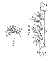
- Figure 1 is a schematic view of the device used to form an image of magnetic toner on a conductive printing roll.
- Figure 2 is a schematic view of a printer using three of the printing rolls prepared in Figure 1.
- Referring now to Figure 1, a roll 11, surfaced with a conductive layer 12, which in turn is covered with a magnetic member 13, is rotated past a magnetic decorator roll 14 fitted with
magnetic toner hopper 15. After the magnetic toner has been applied to magnetic layer 13, by decorator roll 14, AC corona 16 serves to neutralize any electrostatic charges which may be attracting magnetic toner particles to magnetic imaging member 13. Magnetic toner particles which are on non-image areas of magnetic imaging member 13 are removed byvacuum knife 17. The magnetic toner image is then transferred to conductive roll 18 by means of pressure and heat supplied by lamp 19. - The conductive roll with the magnetic toner image is removed from the system. If desired the magnetic toner image may be further treated such as with solvent vapors or heat to further coalesce the magnetic toner particles. Referring now to Figure 2, a plurality of conductive rolls 18, 18', 18" with a non-conductive magnetic toner image are mounted in a multi-stage printer. The magnetic toner areas of rolls 18, 18', 18" are electrostatically charged by means of
DC coronas endless belt 29 supported byrollers DC coronas 33, 34, 35 cause the toner rolls 18, 18', 18" to transfer to substrate 27. Toner which did not transfer to substrate 27 is neutralized byAC coronas vacuum brushes roll 42. - The magnetic imaging member used in the magnetic printing step may be first magnetically structured and then selectively demagnetized in - the background areas by heating such background areas above the Curie point of the magnetic material in the magnetic imaging member to leave a latent magnetic image. Alternatively the latent magnetic image may be formed in the magnetic imaging member by means of a magnetic write head. Preferably the magnetic imaging member is magnetically structured to have from about 40 to 1200 magnetic lines per cm. As used herein, a magnetic line contains one nortli pole and one south pole. Preferably the magnetic imaging member is formed of a layer of acicular chromium dioxide in a binder on an electrically conductive support. The acicular chromium dioxide layer generally is from 1.3 to 50 micrometers in thickness, and preferably is from 4 to 13 micrometers in thickness.
- The magnetic imaging member can be used either mounted in the form of an endless belt supported by a plurality of rolls or mounted on a cylindrical printing roll. The imaging and toning steps are separate entities which do not need to be done consecutively in predetermined sequential fashion. For instance, it may be desired to mount a preimaged magnetic imaging member on a printing roll.
- The imaging member containing the latent magnetic image is then brought into superimposed relationship with the conductive member to which the toner image is to be transferred. At this point a DC corona, situated on the side of the conductive member away from the imaging member bearing the toner, causes the toner to transfer to the conductive member. At this point the conductive member must be insulated from ground.
- After being transferred to the conductive member the toner is temporarily fixed to the conductive member. Generally this is most readily achieved by the application of heat which causes the toner particles to coalesce and become fused to each other as well as to the conductive member. Generally the application of pressure is unnecessary; but if pressure is to be applied the pressure applying means should be covered with a material to which the toner will not adhere, such as poly(tetrafluoroethylene).
- If desired the magnetic toner can be transferred from the magnetic imaging member to an intermediate transfer member and then permanently applied to the conductive member, such as described in US-A-4,292,120.
- The conductive member is then mounted in a suitable electrostatic printing apparatus: Generally the conductive member is mounted on a roller which in turn is part of an electrostatic printing machine.
- Then the toner image on the conductive member is electrostatically charged. This is most readily achieved by exposing the toner image to a DC corona, while electrically grounding the conductive member. Alternatively the conductive member can be electrically charged and then discharged leaving the toner image electrically charged.
- The charged toner image is then decorated with an electrostatic toner. This can be done with a magnetic brush where the toner particles are charged triboelectrically or by charging the toner particles in a cascade type decorator:
- The electrostatic toner is then transferred to a substrate such as cotton, wool, polyester/cotton or their blends, paper or a film. This can be done either electrostatically or by application of pressure or heat and pressure.
- The magnetic toner particles fused to the conductive roll preferably are magnetic pigments encapsulated in a suitable binder. Generally the toner particles have an average size ranging from 10 to 30 um with a preferred average size ranging from 15 to 20 um. Spherical particles such as prepared by spray drying are preferred because of their superior flow properties which can be enhanced by the addition of minute amounts of a flow additive such as fumed silica. A further description of the preparation of toner particles may be found in US-A-3,627,682. When using the apparatus disclosed herein the toner particles should have a low electrical conductivity. If the particles have high conductivity, they will be passed back and forth between the drum and the paper causing a diffuse image and low transfer efficiency. Generally the toner powder electrical conductivity is less than 1 x 10-'3 ohm/cm. The ferro-magnetic component can consist of hard magnetic particles or a binary mixture of hard and soft magnetic particles. The magnetically soft particles can be iron or another high-permeable, low-remanence material, such as certain ferrites, for example, (Zn, Mn)Fe204, or permalloys. The magnetically hard particles can be an iron oxide, preferably Fe304, y-Fez03, other ferrites, for example, BaFe,20,9, chi-iron carbide, chromium dioxide or alloys of Fe304 and nickel or cobalt. A magnetically hard substance has a high-intrinsic coercivity, ranging generally from about 40 to about 40,000 oersteds (1 oersted = 80 A/m) and a high remanence (20 percent or more of the saturation magnetization) when removed from the magnetic field. Such substances are of low permeability and require high fields for magnetic saturation. A magnetically soft substance has low coercivity, for example, one oersted or less, high permeability, permitting saturation to be obtained with a small applied field, and exhibits a remanence of less than 5 percent of the saturation magnetization. A particularly preferred toner has an average particle size of 20 pm and contains 40 weight percent
thermoplastic binder 30 weight percent Fe304 (magnetite) and 30 weight percent soft iron (carbonyl iron). - The electrostatic toner particles used in decorating the electrostatic printing roll are a colorant encapsulated in a suitable binder. Generally the electrostatic toner will have an average particle size of from 15 to 20 pm. Spherical particles such as prepared by spray drying are preferred because of their superior flow properties. Generally the electrostatic toner will contain from 1.0 to 20.0 wt.% pigment and from 80.0 to 99.0 wt.% of a thermoplastic binder. Suitable pigments include copper phthalocyanine, halogenated copper phthalocyanines, quinacridone, quinacridonequinone, etc.
- A magnetic imaging member formed of a 350 p inches (8.9 pm) thick layer of acicular chromium dioxide in a binder on an electrically grounded silver coated rubber roll which is 12 inches (0.3 meter) wide. The magnetic imaging member is magnetically structured to 460 pole reversals/inch (18 pole reversals/mm) or 230 cycles/inch (9 cyc- les/mm) or 55 µm per pole reversal by recording a square wave with a magnetic write head at 35 m Amps and 6 to 8 volts. A film positive of the image to be printed is placed in contact with the magnetic roll and stepwise uniformly illuminated by a Xenon flash at 3.3 KV with a 15° turn per flash passing through the film positive, corresponding to the areas to be printed, absorb the energy of the Xenon flash; whereas the clear areas transmit the light and heat the acicular chromium dioxide beyond its Curie point of about 116°C thereby demagnetizing the exposed magnetized lines of acicular chromium dioxide. A non-conductive toner is fed from a slot in a hopper to decorate the latent magnetic image by means of a decorator. The decorator comprises a rotating magnetic cylinder inside a non-magnetic sleeve. As the magnetic imaging member rotates after being decorated with toner it passes an AC corona which serves to neutralize any electrostatic charges which may cause toner to adhere to the magnetic imaging member. Then a vacuum knife removes stray toner from the non-image areas. The toner is then negatively charged with a DC corona. The toner is then transferred to a positively charged copper sheet having a polyethylene terephthalate film backing. The toner is then fused to the copper sheet. The copper sheet is grounded and the toner fused thereto is positively charged with a DC corona. An electrostatic toner is negatively charged and then poured over the side of the copper sheet to which the charged fused toner is adhered. The negatively charged toner adheres to the charged fused toner and not to the grounded background copper areas. A sheet of paper is laid over the toner and positively charged with a DC corona to effect transfer of the negatively charged toner to the paper. The toner is then fused to the paper by heating.
Claims (6)
Applications Claiming Priority (2)
| Application Number | Priority Date | Filing Date | Title |
|---|---|---|---|
| US39278882A | 1982-06-28 | 1982-06-28 | |
| US392788 | 1982-06-28 |
Publications (2)
| Publication Number | Publication Date |
|---|---|
| EP0097954A1 EP0097954A1 (en) | 1984-01-11 |
| EP0097954B1 true EP0097954B1 (en) | 1986-08-06 |
Family
ID=23552006
Family Applications (1)
| Application Number | Title | Priority Date | Filing Date |
|---|---|---|---|
| EP19830106283 Expired EP0097954B1 (en) | 1982-06-28 | 1983-06-28 | Electrostatic printing process |
Country Status (5)
| Country | Link |
|---|---|
| EP (1) | EP0097954B1 (en) |
| JP (1) | JPS5915951A (en) |
| AU (1) | AU1629183A (en) |
| CA (1) | CA1198148A (en) |
| DE (1) | DE3365133D1 (en) |
Families Citing this family (6)
| Publication number | Priority date | Publication date | Assignee | Title |
|---|---|---|---|---|
| US4883970A (en) * | 1986-08-15 | 1989-11-28 | E. I. Du Pont De Nemours And Company | X-ray intensifying screens containing activated rare earth borates |
| FI84330C (en) * | 1988-06-21 | 1991-11-25 | Valtion Teknillinen | FOERFARANDE FOER XEROGRAFISK TRYCKNING AV TEXTILMATERIAL ELLER DYLIKT. |
| DE4311197A1 (en) * | 1993-04-05 | 1994-10-06 | Patent Treuhand Ges Fuer Elektrische Gluehlampen Mbh | Method for operating an incoherently radiating light source |
| FR2709572B1 (en) * | 1993-06-23 | 1995-10-27 | Nipson | Method of printing at least one image and press for implementation. |
| US6042747A (en) * | 1998-01-22 | 2000-03-28 | Matsushita Electric Industrial Co., Ltd. | Method of preparing high brightness, small particle red-emitting phosphor |
| US6284155B1 (en) | 1999-10-23 | 2001-09-04 | Matsushita Electric Industrial Co., Ltd. | Method for making small particle red emitting phosphors |
Family Cites Families (5)
| Publication number | Priority date | Publication date | Assignee | Title |
|---|---|---|---|---|
| BE655347A (en) * | 1963-11-05 | |||
| DE1597804B2 (en) * | 1967-09-01 | 1977-02-10 | Agfa-Gevaert Ag, 5090 Leverkusen | MULTIPLICATION PROCESS AND DEVICE FOR CARRYING OUT THE PROCESS |
| US4099186A (en) * | 1976-03-31 | 1978-07-04 | E. I. Du Pont De Nemours And Company | Magnetic printing process and apparatus |
| US4339518A (en) * | 1979-10-18 | 1982-07-13 | Daikin Kogyo Co., Ltd. | Process of electrostatic printing with fluorinated polymer toner additive |
| US4292120A (en) * | 1980-04-10 | 1981-09-29 | E. I. Du Pont De Nemours & Company | Process of forming a magnetic toner resist using a transfer film |
-
1983
- 1983-06-23 CA CA000431043A patent/CA1198148A/en not_active Expired
- 1983-06-27 JP JP58114464A patent/JPS5915951A/en active Pending
- 1983-06-27 AU AU16291/83A patent/AU1629183A/en not_active Abandoned
- 1983-06-28 EP EP19830106283 patent/EP0097954B1/en not_active Expired
- 1983-06-28 DE DE8383106283T patent/DE3365133D1/en not_active Expired
Also Published As
| Publication number | Publication date |
|---|---|
| EP0097954A1 (en) | 1984-01-11 |
| JPS5915951A (en) | 1984-01-27 |
| DE3365133D1 (en) | 1986-09-11 |
| AU1629183A (en) | 1984-01-05 |
| CA1198148A (en) | 1985-12-17 |
Similar Documents
| Publication | Publication Date | Title |
|---|---|---|
| US3093039A (en) | Apparatus for transferring powder images and method therefor | |
| US3900001A (en) | Developing apparatus | |
| US3239465A (en) | Xerographic developer | |
| US2895847A (en) | Electric image development | |
| US3643629A (en) | Magnetic powder applicator | |
| US3739748A (en) | Donor for touchdown development | |
| US3696783A (en) | Automated touchdown developement system | |
| US4242434A (en) | Toner composition for multiple copy electrostatic photography | |
| US4357618A (en) | Electrostatic imaging apparatus | |
| US3811765A (en) | Contact-transfer electrostatic printing system | |
| EP0097954B1 (en) | Electrostatic printing process | |
| JP2003533748A (en) | Process for developing electrostatic images with optimized settings | |
| US4267248A (en) | Magnet-brush development process of electric pattern images | |
| CA1101268A (en) | Process for magnetically transferring a powder image | |
| US3906121A (en) | Electrostatic development method using magnetic brush configuration transport | |
| US3806355A (en) | Electrostatic printing apparatus and method | |
| US4233382A (en) | Electrostatic transfer of magnetically held toner images | |
| US4636449A (en) | Electrostatic printing process | |
| US4216282A (en) | AC corona to remove background from the imaging member of a magnetic copier | |
| US4254206A (en) | Process for magnetically transferring a powder image | |
| CA1051263A (en) | Removal of carrier beads from photosensitive drum | |
| GB2094672A (en) | Developing electrostatic latent images | |
| US3245823A (en) | Electrostatic image development apparatus | |
| US4427412A (en) | Magnetic printing of disperse-dyeable textile material | |
| EP0573096B1 (en) | Image-forming device |
Legal Events
| Date | Code | Title | Description |
|---|---|---|---|
| PUAI | Public reference made under article 153(3) epc to a published international application that has entered the european phase |
Free format text: ORIGINAL CODE: 0009012 |
|
| AK | Designated contracting states |
Designated state(s): BE DE FR GB IT |
|
| 17P | Request for examination filed |
Effective date: 19840710 |
|
| GRAA | (expected) grant |
Free format text: ORIGINAL CODE: 0009210 |
|
| AK | Designated contracting states |
Kind code of ref document: B1 Designated state(s): BE DE FR GB IT |
|
| ITF | It: translation for a ep patent filed |
Owner name: ING. C. GREGORJ S.P.A. |
|
| REF | Corresponds to: |
Ref document number: 3365133 Country of ref document: DE Date of ref document: 19860911 |
|
| ET | Fr: translation filed | ||
| PLBE | No opposition filed within time limit |
Free format text: ORIGINAL CODE: 0009261 |
|
| STAA | Information on the status of an ep patent application or granted ep patent |
Free format text: STATUS: NO OPPOSITION FILED WITHIN TIME LIMIT |
|
| 26N | No opposition filed | ||
| PG25 | Lapsed in a contracting state [announced via postgrant information from national office to epo] |
Ref country code: GB Effective date: 19880628 |
|
| BERE | Be: lapsed |
Owner name: E.I. DU PONT DE NEMOURS AND CY Effective date: 19880630 |
|
| GBPC | Gb: european patent ceased through non-payment of renewal fee | ||
| PG25 | Lapsed in a contracting state [announced via postgrant information from national office to epo] |
Ref country code: FR Free format text: LAPSE BECAUSE OF NON-PAYMENT OF DUE FEES Effective date: 19890228 |
|
| PG25 | Lapsed in a contracting state [announced via postgrant information from national office to epo] |
Ref country code: DE Effective date: 19890301 |
|
| REG | Reference to a national code |
Ref country code: FR Ref legal event code: ST |
|
| PG25 | Lapsed in a contracting state [announced via postgrant information from national office to epo] |
Ref country code: BE Effective date: 19890630 |