EP0097548B1 - Groupe motopompe pour puits de forage et procédé de protection s'y rapportant - Google Patents
Groupe motopompe pour puits de forage et procédé de protection s'y rapportant Download PDFInfo
- Publication number
- EP0097548B1 EP0097548B1 EP83401072A EP83401072A EP0097548B1 EP 0097548 B1 EP0097548 B1 EP 0097548B1 EP 83401072 A EP83401072 A EP 83401072A EP 83401072 A EP83401072 A EP 83401072A EP 0097548 B1 EP0097548 B1 EP 0097548B1
- Authority
- EP
- European Patent Office
- Prior art keywords
- motor
- pump
- shaft
- sealing system
- fluid
- Prior art date
- Legal status (The legal status is an assumption and is not a legal conclusion. Google has not performed a legal analysis and makes no representation as to the accuracy of the status listed.)
- Expired
Links
Images

Classifications
-
- F—MECHANICAL ENGINEERING; LIGHTING; HEATING; WEAPONS; BLASTING
- F04—POSITIVE - DISPLACEMENT MACHINES FOR LIQUIDS; PUMPS FOR LIQUIDS OR ELASTIC FLUIDS
- F04D—NON-POSITIVE-DISPLACEMENT PUMPS
- F04D13/00—Pumping installations or systems
- F04D13/02—Units comprising pumps and their driving means
- F04D13/06—Units comprising pumps and their driving means the pump being electrically driven
- F04D13/08—Units comprising pumps and their driving means the pump being electrically driven for submerged use
- F04D13/10—Units comprising pumps and their driving means the pump being electrically driven for submerged use adapted for use in mining bore holes
Definitions
- the present invention relates to a motor pump unit for a wellbore, in particular used for pumping hydrocarbons, this group being intended to be immersed in an external medium.
- the invention also relates to a protection method relating to such a group.
- Known devices of this kind include a motor housed in a sealed enclosure and axially coupled to a pump housed in a cylindrical body and formed by a number of stages.
- a sealing system generally placed on the outlet of the motor shaft in the vicinity of the coupling with the pump, seals the enclosure of the engine to prevent the penetration into it of the fluid pumped into which the group is immersed in. Indeed, a lack of tightness quickly leads to the destruction of the engine by two joint phenomena.
- the penetration of solid particles of the sand type causes wear and then seizure of the stops and bearings.
- the penetration of the pumped fluid which generally comprises an appreciable proportion of water highly charged with salts, causes destruction of the electrical windings.
- the motor with its sealing system is generally located below the pump.
- the sealing system generally comprises a rotating mechanical seal, one of the cooperating parts of which is in direct contact with the particles in suspension in the pumped fluid, which are liable to accumulate in the vicinity of the seal and to rapidly cause the deterioration of the cooperating parts.
- the present invention aims to produce a pump unit in which the rotary mechanical seal is sufficiently protected from damage due to solid particles so that its life is at least of the order of the interval between two routine maintenance operations of the group. .
- a motor pump unit for wellbore comprising a motor housed in a sealed enclosure and axially coupled to a pump housed in a cylindrical body and formed by a number of stages, a sealing system on the output of the motor shaft, and a sweeping circuit withdrawing pumped fluid from an area of average radius of an intermediate space of the pump, characterized in that the sweeping circuit comprises a channel drilled in the axis of the pump shaft opening into a first annular space formed by the radial clearance of the bearing carrying this shaft closest to the motor, a second annular space located around the trees and externally limited by a chimney integral with the pump body, the pumped fluid circuit also being annular and located outside the chimney, and ejection channels directed towards the outside environment in the vicinity of the sealing system of the motor shaft.
- This circuit carries out during the operation of the pump set a continuous scanning of the area in the vicinity of the sealing system by means of a clean fluid thanks to the fact that the declutching fluid is taken from an average radius of the pump, the solid particles pumped fluid being removed from the sampling area by centrifugation.
- the passage through the annular space of a bearing plays an additional protective role by making it possible to stop any particles and the annular part limited by a chimney allows total isolation of the scanning circuit.
- a protective piece wedged on the shaft located on the side of the pump with respect to the sealing system, and of a larger diameter. to that of said system.
- this part constitutes, in particular during periods of standstill, a protective cap for the lining by preventing particles from coming to deposit on it.
- the protective part advantageously comprises a peripheral rim extending up to the internal wall of the enclosure of the motor, in order to improve the effectiveness of the protection.
- the rim of the protective part provides, with a support part for the seal, an annular space located opposite the ejection channels.
- a second aspect of the invention relates to a method of protecting the sealing system of a pump unit for wells of drilling, in accordance with the first aspect, by means of a selected part of the pumped liquid taken between two stages of the pump, characterized in that this selected part of the pumped liquid is channeled in the vicinity of the sealing system of the motor as liquid washing, then ejected into the outside environment.
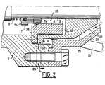
- the pump unit comprises a motor 1, housed in a sealed enclosure 2 filled with lubricant, and the shaft 3 of which is coupled by means of a sleeve 4 to the shaft of a pump 6.
- the shaft 3 leaves the enclosure 2 by a rotating mechanical seal 7 ensuring the tightness of the passage and composed of a fixed part 7a fixed on a support part 8 secured to the enclosure 2 and of a rotating part 7b fixed on the shaft and applied to the fixed part 7a by a spring 9.
- the pump 6 comprises a number of stages 11 in series, each composed of movable vanes 11a keyed onto the shaft 5 and fixed vanes 11b secured to a substantially cylindrical pump body 12 bolted to the enclosure 2.
- the pump body 12 In the vicinity of its connection to the motor, the pump body 12 has a certain number of peripheral windows 13 which constitute the suction orifices of the pump, through which the pumped fluid penetrates according to the arrows P into the annular space formed between a chimney 22 integral with the pump body 12 and the latter.
- the shaft 5 is drilled with an axial channel 14 which communicates, to the right of FIG. 1, with a radial channel 15 formed in the shaft 5 and in a ring 16 surrounding this shaft opposite an intermediate space 10 of the pump located between two series of stages.
- Opposite channel 15 is a channel 17 bent to open in an area of, mean radius of the pump.
- the shaft 5 In line with each of the bearings 19 located upstream (relative to the pumping direction), the shaft 5 has a radial channel 21 which opens into the radial clearance between the bearing and the corresponding ring.
- a protective part 24 is wedged on the shaft 3 of the motor by means of a sleeve 25.
- the part 24, located on the side of the pump with respect to the lining 7, has a diameter greater than that of this lining and it has a peripheral rim 26 which extends to the internal wall of the enclosure 2 of the engine providing a clearance 27 with this wall ( Figure 2).
- the rim 26 provides, with the part 8 supporting the lining 7, a flat annular space 28 opposite which are provided radial ejection channels 29.
- the pumped liquid Under the effect of the pressure generated by the pump in the intermediate space 10, passes through the bent channel 17 and through the radial channel 15 to return upstream through the axial channel 14 according to the arrows L.
- part of this liquid escapes through the corresponding channel 21 towards the radial clearance of the pad to lubricate it, then joins the pumping flow.
- the liquid which escapes from the radial clearance 19a of this bearing on the engine side is channeled in the annular space 31 located between the shafts and the chimney 22 to reach the clearance 27 between the rim 26 of the part 24 and the enclosure 2, and be ejected through the channels 29 under the effect of the centrifugal force originating from the wall effect of the rim 26.
- the circuit L of sampled fluid which passes through 27 and 29 opposes the penetration and accumulation of pumped fluid and solid particles, allowing the annular space 33 to remain filled with clean fluid from the engine.
- the particles inside the pump decant along an opposite path from the arrows P and are therefore found outside the protected space. If certain particles manage to pass inside the chimney 22, they will be ejected as soon as the engine is restarted.
Landscapes
- Engineering & Computer Science (AREA)
- Mining & Mineral Resources (AREA)
- Mechanical Engineering (AREA)
- General Engineering & Computer Science (AREA)
- Structures Of Non-Positive Displacement Pumps (AREA)
- Applications Or Details Of Rotary Compressors (AREA)
- Lubrication Of Internal Combustion Engines (AREA)
Applications Claiming Priority (2)
| Application Number | Priority Date | Filing Date | Title |
|---|---|---|---|
| FR8209745 | 1982-06-04 | ||
| FR8209745A FR2528124B1 (fr) | 1982-06-04 | 1982-06-04 | Groupe motopompe pour puits de forage et procede de protection s'y rapportant |
Publications (2)
| Publication Number | Publication Date |
|---|---|
| EP0097548A1 EP0097548A1 (fr) | 1984-01-04 |
| EP0097548B1 true EP0097548B1 (fr) | 1987-08-19 |
Family
ID=9274635
Family Applications (1)
| Application Number | Title | Priority Date | Filing Date |
|---|---|---|---|
| EP83401072A Expired EP0097548B1 (fr) | 1982-06-04 | 1983-05-27 | Groupe motopompe pour puits de forage et procédé de protection s'y rapportant |
Country Status (6)
| Country | Link |
|---|---|
| US (1) | US4553909A (no) |
| EP (1) | EP0097548B1 (no) |
| DE (2) | DE3373123D1 (no) |
| ES (1) | ES8403575A1 (no) |
| FR (1) | FR2528124B1 (no) |
| NO (1) | NO155019C (no) |
Families Citing this family (8)
| Publication number | Priority date | Publication date | Assignee | Title |
|---|---|---|---|---|
| US5845709A (en) * | 1996-01-16 | 1998-12-08 | Baker Hughes Incorporated | Recirculating pump for electrical submersible pump system |
| US5779434A (en) * | 1997-02-06 | 1998-07-14 | Baker Hughes Incorporated | Pump mounted thrust bearing |
| US7841395B2 (en) * | 2007-12-21 | 2010-11-30 | Baker Hughes Incorporated | Electric submersible pump (ESP) with recirculation capability |
| US8425667B2 (en) * | 2010-08-31 | 2013-04-23 | General Electric Company | System and method for multiphase pump lubrication |
| US8721181B2 (en) * | 2010-09-29 | 2014-05-13 | Baker Hughes Incorporated | Keyless bearing sleeve for subterranean applications |
| GB201507261D0 (en) | 2015-04-28 | 2015-06-10 | Coreteq Ltd | Motor and pump parts |
| JP2020197139A (ja) * | 2019-05-31 | 2020-12-10 | 三菱重工業株式会社 | 油田用ポンプ |
| WO2022176092A1 (ja) * | 2021-02-18 | 2022-08-25 | 三菱重工業株式会社 | 原油採掘ポンプ |
Family Cites Families (10)
| Publication number | Priority date | Publication date | Assignee | Title |
|---|---|---|---|---|
| US1778787A (en) * | 1927-04-15 | 1930-10-21 | Reda Pump Company | Motor protector |
| US2001172A (en) * | 1931-02-21 | 1935-05-14 | Wintroath Pumps Ltd | Submersible motor driven pump |
| US2043236A (en) * | 1934-06-01 | 1936-06-09 | David J Conant | Submergible motor |
| US2193903A (en) * | 1938-06-18 | 1940-03-19 | Fmc Corp | Liquid seal |
| US2809590A (en) * | 1954-01-29 | 1957-10-15 | Robert J Brown | Electric motor driven pump |
| US2783400A (en) * | 1955-08-05 | 1957-02-26 | Reda Pump Company | Protecting unit for oil-filled submergible electric motors |
| US3022739A (en) * | 1959-07-24 | 1962-02-27 | Fairbanks Morse & Co | Motor and pump apparatus |
| US3288075A (en) * | 1964-11-27 | 1966-11-29 | Tait Mfg Co The | Pumps |
| US3850550A (en) * | 1971-08-05 | 1974-11-26 | Hydr O Matic Pump Co | Centrifugal pump and motor |
| US3975117A (en) * | 1974-09-27 | 1976-08-17 | James Coolidge Carter | Pump and motor unit with inducer at one end and centrifugal impeller at opposite end of the motor |
-
1982
- 1982-06-04 FR FR8209745A patent/FR2528124B1/fr not_active Expired
-
1983
- 1983-05-20 NO NO831812A patent/NO155019C/no unknown
- 1983-05-27 DE DE8383401072T patent/DE3373123D1/de not_active Expired
- 1983-05-27 EP EP83401072A patent/EP0097548B1/fr not_active Expired
- 1983-05-27 DE DE198383401072T patent/DE97548T1/de active Pending
- 1983-05-31 ES ES522838A patent/ES8403575A1/es not_active Expired
- 1983-06-01 US US06/500,177 patent/US4553909A/en not_active Expired - Fee Related
Also Published As
| Publication number | Publication date |
|---|---|
| DE3373123D1 (en) | 1987-09-24 |
| NO831812L (no) | 1983-12-05 |
| US4553909A (en) | 1985-11-19 |
| NO155019C (no) | 1987-01-28 |
| DE97548T1 (de) | 1984-04-12 |
| ES522838A0 (es) | 1984-03-16 |
| EP0097548A1 (fr) | 1984-01-04 |
| FR2528124A1 (fr) | 1983-12-09 |
| FR2528124B1 (fr) | 1987-04-03 |
| ES8403575A1 (es) | 1984-03-16 |
| NO155019B (no) | 1986-10-20 |
Similar Documents
| Publication | Publication Date | Title |
|---|---|---|
| CA2204664C (fr) | Systeme de pompage polyphasique et centrifuge | |
| CA2637643C (fr) | Separateur a ecoulement cyclonique | |
| CA2946958C (fr) | Module de turbomachine comportant un carter autour d'un equipement avec un capot de recuperation d'huile de lubrification | |
| EP2183508B1 (fr) | Pompe a vide de type seche comportant un dispositif d'etancheite aux fluides lubrifiants et element centrifugeur equipant un tel dispositif | |
| EP0097548B1 (fr) | Groupe motopompe pour puits de forage et procédé de protection s'y rapportant | |
| EP0270444A1 (fr) | Système de lubrification pour démarreur de turbomachine | |
| CA2621837C (fr) | Systeme de deshuilage pour moteur d'aeronef | |
| FR2675213A1 (fr) | Systeme formant barriere pour l'huile de lubrification des paliers d'un compresseur centrifuge muni de joints d'etancheite a labyrinthe installe dans un environnement confine. | |
| EP0097549B1 (fr) | Dispositif pour réaliser l'étanchéite d'un moteur immergeable et moteur s'y rapportant | |
| CA2682004A1 (fr) | Double joint a levre pressurise | |
| FR2465064A1 (fr) | Dispositif pour empecher les impuretes de la boue de forage de passer par les roulements d'un moteur de fond de puits de forage | |
| EP3269994A1 (fr) | Systeme de freinage ameliore pour machine hydraulique | |
| FR2548752A1 (fr) | Joint liquide pour gaz avec balayage de fluide | |
| EP0491624B1 (fr) | Système d'étanchéité pour palier d'une machine, notamment d'une turbomachine | |
| EP0063062B1 (fr) | Dispositif d'étanchéité pour machine rotative à fluide hydraulique | |
| FR2565295A1 (fr) | Pompe a vide rotative etanchee dans l'huile | |
| CA2915106C (fr) | Tourillon pour turbine haute pression, et turboreacteur incluant un tel tourillon | |
| FR2497868A1 (fr) | Ensemble formant palier et joint d'etancheite pour arbre tournant | |
| EP0554803B1 (fr) | Pompe centrifuge multiétages | |
| BE1009541A6 (fr) | Regulateur de debit. | |
| EP3978793A1 (fr) | Systeme de connexion en rotation muni d'une roue libre et d'un dispositif de lubrification | |
| FR2503584A1 (fr) | Centrifugeuse pour l'epuration des liquides moteurs des systemes hydrauliques | |
| CA2822038C (fr) | Installation de pompage pour puits profond | |
| FR2508563A1 (fr) | Motopompe a moteur electrique a rotor noye | |
| FR2775321A1 (fr) | Dispositif pour l'equilibrage de la poussee axiale dans une pompe centrifuge |
Legal Events
| Date | Code | Title | Description |
|---|---|---|---|
| PUAI | Public reference made under article 153(3) epc to a published international application that has entered the european phase |
Free format text: ORIGINAL CODE: 0009012 |
|
| 17P | Request for examination filed |
Effective date: 19830601 |
|
| AK | Designated contracting states |
Designated state(s): DE GB IT NL |
|
| ITCL | It: translation for ep claims filed |
Representative=s name: BARZANO' E ZANARDO ROMA S.P.A. |
|
| TCNL | Nl: translation of patent claims filed | ||
| DET | De: translation of patent claims | ||
| ITF | It: translation for a ep patent filed |
Owner name: BARZANO' E ZANARDO ROMA S.P.A. |
|
| GRAA | (expected) grant |
Free format text: ORIGINAL CODE: 0009210 |
|
| AK | Designated contracting states |
Kind code of ref document: B1 Designated state(s): DE GB IT NL |
|
| PG25 | Lapsed in a contracting state [announced via postgrant information from national office to epo] |
Ref country code: NL Effective date: 19870819 |
|
| REF | Corresponds to: |
Ref document number: 3373123 Country of ref document: DE Date of ref document: 19870924 |
|
| NLV1 | Nl: lapsed or annulled due to failure to fulfill the requirements of art. 29p and 29m of the patents act | ||
| PG25 | Lapsed in a contracting state [announced via postgrant information from national office to epo] |
Ref country code: GB Effective date: 19880527 |
|
| PLBE | No opposition filed within time limit |
Free format text: ORIGINAL CODE: 0009261 |
|
| STAA | Information on the status of an ep patent application or granted ep patent |
Free format text: STATUS: NO OPPOSITION FILED WITHIN TIME LIMIT |
|
| 26N | No opposition filed | ||
| GBPC | Gb: european patent ceased through non-payment of renewal fee | ||
| PG25 | Lapsed in a contracting state [announced via postgrant information from national office to epo] |
Ref country code: DE Effective date: 19890201 |