EP0097258B1 - Equipement de calcul et son procédé d'exploitation - Google Patents
Equipement de calcul et son procédé d'exploitation Download PDFInfo
- Publication number
- EP0097258B1 EP0097258B1 EP83105178A EP83105178A EP0097258B1 EP 0097258 B1 EP0097258 B1 EP 0097258B1 EP 83105178 A EP83105178 A EP 83105178A EP 83105178 A EP83105178 A EP 83105178A EP 0097258 B1 EP0097258 B1 EP 0097258B1
- Authority
- EP
- European Patent Office
- Prior art keywords
- allocation
- user
- functional capability
- request
- functional
- Prior art date
- Legal status (The legal status is an assumption and is not a legal conclusion. Google has not performed a legal analysis and makes no representation as to the accuracy of the status listed.)
- Expired - Lifetime
Links
Images


Classifications
-
- G—PHYSICS
- G06—COMPUTING; CALCULATING OR COUNTING
- G06F—ELECTRIC DIGITAL DATA PROCESSING
- G06F9/00—Arrangements for program control, e.g. control units
- G06F9/06—Arrangements for program control, e.g. control units using stored programs, i.e. using an internal store of processing equipment to receive or retain programs
- G06F9/46—Multiprogramming arrangements
- G06F9/468—Specific access rights for resources, e.g. using capability register
-
- G—PHYSICS
- G06—COMPUTING; CALCULATING OR COUNTING
- G06F—ELECTRIC DIGITAL DATA PROCESSING
- G06F16/00—Information retrieval; Database structures therefor; File system structures therefor
-
- G—PHYSICS
- G06—COMPUTING; CALCULATING OR COUNTING
- G06F—ELECTRIC DIGITAL DATA PROCESSING
- G06F9/00—Arrangements for program control, e.g. control units
- G06F9/06—Arrangements for program control, e.g. control units using stored programs, i.e. using an internal store of processing equipment to receive or retain programs
- G06F9/46—Multiprogramming arrangements
- G06F9/461—Saving or restoring of program or task context
- G06F9/463—Program control block organisation
-
- G—PHYSICS
- G06—COMPUTING; CALCULATING OR COUNTING
- G06F—ELECTRIC DIGITAL DATA PROCESSING
- G06F11/00—Error detection; Error correction; Monitoring
- G06F11/07—Responding to the occurrence of a fault, e.g. fault tolerance
- G06F11/14—Error detection or correction of the data by redundancy in operation
- G06F11/1402—Saving, restoring, recovering or retrying
- G06F11/1474—Saving, restoring, recovering or retrying in transactions
-
- G—PHYSICS
- G06—COMPUTING; CALCULATING OR COUNTING
- G06F—ELECTRIC DIGITAL DATA PROCESSING
- G06F2201/00—Indexing scheme relating to error detection, to error correction, and to monitoring
- G06F2201/80—Database-specific techniques
Definitions
- This invention relates to a computing apparatus and to a method for operating such a computing apparatus. More specifically, it relates to the control of intersubsystem access to computing functions and data in a multi-processing environment.
- a plurality of subsystems provide computing functions and manage data for a plurality of applications. These subsystems and applications execute in various address spaces and according to various priorities, key states, and allocation levels, thus enabling multiple users to share the computing resources of the system.
- IBM System/370 IBM System/370
- MVS Multiple Virtual Systems
- the usual technique for controlling intersubsystem access is to store information i ⁇ control blocks describing the user's state, including the current access protocol and allocation level, and to include inline checks throughout the target subsystem to make sure correct processing occurs.
- These inline checks can and do often result in greatly increased complexity and execution time inefficiencies.
- IBM IMSNS Version 1 Program Number 5740-XX2
- Release 1.5 batch message processing (BMP) regions and message processing (MPP) regions contain application programs for processing data bases managed by a control region.
- An application region must first be loaded with the IMS control program, then with the application control task, and then those cooperate to bring in the user application subtask.
- a method for operating a computing apparatus including at least one subsystem having a pool of available functional modules for supporting a plurality of user requests under various access protocols and allocation levels.
- the new method assures that user requests valid only under some protocols and allocations levels are not executed on behalf of users authorized only for different protocols and levels, and includes the following steps: (1) generating for a user an allocation descriptor describing the user's functional capability; (2) responsive to a request from a user which does not imply a change in functional capability, executing a functional module on behalf of the user according to the user's currently allocated functional capability; and (3) responsive to a request from a user which implies a change in the user's functional capability, allocating functional modules to the user according to a new functional capability only if this allocation is allowed by the user's current functional capability.
- a computing system includes at least one subsystem having a pool of ayailable functional modules for supporting a plurality of user requests under various access protocols and allocation levels.
- Execution means are provided for assuring that user requests valid only under some protocols and allocation levels are not executed on behalf of users authorized only for different protocols and levels, such execution means including means for generating an allocation descriptor describing a user's functional capability; means responsive to a request from a user which does not imply a change in functional capability for executing a functional module on behalf of the user according to the user's currently allocated functional capability; and means responsive to a request from a user which implies a change in the user's functional capability for allocating functional modules to the user according to a new functional capability only if the allocation is allowed by the user's current functional capability.
- a storage map is illustrated for a typical IBM MVS system 50, including common system area (CSA) 60, nucleus 62, and a collection of private address spaces 64 comprising batch address space 65, TSO address space 66, CICS address space 67, IMSNS address spaces 68, 69, and data base management system (DBMS) address spaces master (MSTR) 71 and data base manager (DBM) 74.
- CICS address space 67 is an example of a single address space for a logical subsystem (SASS) and IMS address spaces 68, 69 are an example of multi-address spaces for one logical subsystem (MASS).
- a number of task control blocks (TCBs) are illustrated.
- Batch subsystem address spaces 65 and 66 show only application TCBs 85, there being no control TCB required. Each TCB 85 represents a single, independent application task or work unit.
- a control (or coordinator) TCB 80 is associated with a plurality of subordinate (that is, non-coordinator) application TCBs 81, 82 in a logical work unit contained within a single address space.
- MASS address spaces 68, 69 a control TCB in address space 68 is shown connected to two application task TCBs in address spaces 69.
- Address spaces 65, 66, 67, 68, and 69 are examples of allied address spaces 86.
- Data base management system 70 address space MSTR 71 includes modules providing control, recovery, and logging functions. Thus, log 75 and archive log 87 is shown connected to this address space 71.
- DBMS 70 address space DBM 74 includes modules controlling access to data repository 76. Such modules may provide a relational data base language such as the IBM Sequel Query Language (SQL), including a data definition language (DDL) and data manipulation language (DML).
- SQL IBM Sequel Query Language
- DDL data definition language
- DML data manipulation language
- module SSAM 73 Included within DBMS MSTR address space 71 is module SSAM 73, meaning subsystem support of allied address spaces. Some of the functions performed by SSAM are executed in common system area CSA 60, as is illustrated by module SSAM 72. The procedures and structures implementing the present invention reside, for the most part, in SSAM 72, 73.
- Any application 80,81, 82, 85 or system program may become a user of DBMS 70.
- any program, task, or address space is allowed to identify to DBMS 70.
- Users of DBMS 70 can be of any authority, be executing in any key or state managed by MVS 50.
- DBMS 70 will insure that only data 76 authorized to the user program can be examined by that program (such as TCBs 80, 81, 82, 85), most DBMS 70 data and control blocks are in address spaces 71, 74 different than users 80, 81, 82, 85, and are maintained in MVS 50 storage pools which are fetch protected and in a supervisor key.
- the SSAM components 72, 73 of DBMS MSTR 71 enable DBMS 70 to support several different access protocols, including BATCH, SASS, and MASS access protocols to be described hereinafter in connection with Figures 2-6.
- a facility In a subsystem, such as DBMS 70, supporting several different access protocols, some facility must be provided to insure that requests, such as those initiated of DBMS 70 by tasks 80, 81, 82, 85, valid only under some protocols are not issued by users of one of the other protocols. Further, it is useful to provide a facility which is able to rearrange the functions in a pool of available processors within a subsystem, such as DBMS 70, to produce an entirely new protocol without changing previously developed processors and without developing new ones. These facilities are provided by the SSAM components 72, 73 of this invention (hereafter referred to merely as SSAM 73).
- SSAM 73 is a resource manager within DBMS 70 and controls connections between DBMS 70 and other address spaces 64 running application programs anchored to TCBs 80, 81, 82, 85) hereafter referred to, generically, as TCBs 85).
- TCBs 85 running application programs anchored to TCBs 80, 81, 82, 85
- the characteristics of a "resource manager" are described in copending EP application EP-A-0097234 by E. Jenner, "Method and Apparatus for Restarting a Computing System".
- An allocation descriptor describes all the generic operation/specific processor pairings (GOR/SOP pairs) which should be allocated, and indicates some prerequisites which must be met before allocation should be performed. These allocation descriptors are the SSAM agent parameter list entry descriptors (SAED), to be described hereafter.
- SAED SSAM agent parameter list entry descriptors
- the function capability represents the current capability of any user of subsystem 70 services. It describes and allows access to all generic operation requests (GORs) allowed at the current allocation level for the appropriate access protocol. This functional capability will be defined hereafter in terms of the generic operations (GORs) this user is anchored to along with the SQL requests and commands available to the user when at the application state.
- a GOR/SOP pair is a one to one linkup from a single generic operation request (GOR) to a single specific operation processor (SOP). This establishes which processor is responsible for handling that GOR when this particular allocation is complete.
- GOR is a request which is defined over more than one access protocol. Minor differences or restrictions may exist between access protocols.
- a SOP is a processor which implements a GOR for one or more access protocols. SOPs are invoked via program call (PC) and are completely shielded from unauthorized entry by the linkage mechanism established at allocation.
- the identify (IDEN) SOP is an exception in that its entry conditions cannot be enforced through allocation of normal PC linkages.
- PC is a facility provided by MVS for inter-address space communications and transfer of control.
- the allocation level also referred to as state, indicates the current allocation and authority level of a user (such as a TCB 81) and implies which previous levels of allocation and authority checking have been performed before getting to the current one.
- An access protocol is a collection of predefined GOR descriptions which completely describe one way of accessing a subsystem's services.
- An allocation generic operation request is a generic operation request (GOR) for which an allocation process is implied.
- GOR generic operation request
- IDEN, SIGN, and CTHD generic operation requests are the IDEN, SIGN, and CTHD generic operation requests.
- IDEN and CTHD always imply an allocation process.
- SIGN implies an allocation when requested from the identify or thread allocation level (that is, the identified and application states), but not when requested at the signon allocation level (that is, the signed on state).
- An allocation specific operation processor is a specific operation processor which implements an allocation generic operation request. In the embodiment of the invention to be described, it is a SOP which generates a new function vector list (FVL) during allocation.
- FVL new function vector list
- SSAM 73 manages allocation descriptors which describe completely a user's functional capability. These descriptors are named according to a combination of the access protocol the user is requesting, the level of authority he is requesting (via the particular request he makes), and the presence or absence of certain key parameters which effect his capabilities while executing. The descriptor contains a complete list of what the caller is allowed to do at this level of authority, and is used to allocate functions to the user.
- DBMS 70 provides support for a number of generic operation requests (GORs) under a number of access protocols and allocation levels (or states). These allocation levels allow DBMS 70 to control the execution environment of its users.
- GORs generic operation requests
- the interaction of access protocol and allocation level produce the following characteristics of GORs: some GORs are invalid at some allocation levels and some access protocols, and the specific requirements or semantic of any GOR may be different between access protocols or allocation level within a single access protocol. Some allocation levels may not be required or defined under some access protocols.
- implementation flexibility is provided by allowing sharing of SOPs where this is useful, and allowing separate implementations where the operations are less similar. Each SOP is insured that only authorized entries will be made so no processing time must be spent validating entry. In addition, no SOP is forced to interpret its requestor's allocation level and access protocol to perform the correct function.
- the BATCH protocol is provided for application programs that do not have resource management and recovery functions, such as those of batch region 65 and TSO region 66.
- the single address space subsystem (SASS) protocol is provided for subsystems that do have resource management and recovery functions but operate in one MVS address space only, such as CICS region 67.
- the multiple address space subsystem (MASS) protocol is provided for subsystems that do have resource management and recovery functions but operate in more than one MVS address space, such as IMS 68, 69.
- DBMS 70 provides three additional GORs to support database service requests, the bind function for plans and utility functions, and one GOR to perform command processing.
- IDEN Identify
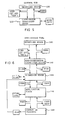
- FIG. 3 is illustrated the possible states of authority and capability which can exist between MASS allied memory control coordinator TCBs and DBMS 70, while Figure 4 illustrates those for MASS dependent memory program control or other non-coordinator TCBs.
- RC recovery coordinator
- the TCB is given the functional capability of having executed on its behalf the SIGN and TERM GORs, the former for establishing signed-on state 124.
- the TCB has the functional capability represented by GORs SIGN, CTHD, and TERM, with CTHD moving the TCB into application state 126. In state 126, SIGN, SYNC, PREP, and TERM GORs are available to the TCB.
- a PREP GOR moves the TCB into the commit in progress state 128 where, halfway through a two phase commit process, the TCB is only given the functional capability of the COMM, ABRT, and TERM GORs.
- Different specific operation processors SOPs
- SIGN GORs are executed for SIGN GORs requested at the identified, signed-on and application states 122, 124, and 126 respectively.
- the SIGN GOR available at application state 126 is used to work through a queue of users accessing the same data, without requiring IDEN and SIGN at state 124 for each member of the queue with each access to data 76.
- FIG. 5 is illustrated the possible states of authority and capability which can exist between SASS allied memory control.
- coordinator TCB 80 and DBMS 70 while Figure 6 illustrates those for SASS dependent memory program control or other non-coordinator TCBs 81, 82.
- RC recovery coordinator
- the TCB is given the functional capability of having executed on its behalf the SIGN and TERM GORs, the former for establishing signed-on state 144.
- the TCB has the functional capability represented by GORs SIGN, CTHD, and TERM, with CTHD moving the TCB into application state 146. In state 146, SIGN, SYNC, PREP, and TERM GORs are available to the TCB.
- a PREP GOR moves the TCB into the commit in progress state 148 where, halfway through a two phase commit process, the TCB is only given the functional capability of the COMM, ABRT, and TERM GORs.
- Different specific operation processors SOPs
- SIGN GORs are executed for SIGN GORs requested at the identified, signed-on and application states 142, 144, and 146 respectively.
- the SIGN GOR available at application state 146 is used to work through a queue of users acessing the same data, without requiring IDEN and SIGN at state 144 for each member of the queue with each access to data 76.
- Identify allows an application TCB to identify itself to DBMS 70.
- An allied agent having authorization to appropriate functions is created and the calling TCBs subsystem affinity table (SSAT) entry for the subsystem is filled in so that DBMS 70 can find its related structures and invoke other DBMS services.
- SSAT subsystem affinity table
- This GOR is implemented in code modules ID30 (which calls AM00) and ID50.
- Module ID30, SSAM Identify Processing Routine establishes allied users connection with DBMS 70 and allows use of further requests via the program request handler (PRH) interface, as is set forth in Table 1.
- PRH program request handler
- Module ID50 Create an Identify Level Allied Agent, creates an identify level allied agent using a copy of the descriptor supplied by the caller, updates the given agent (AGNT) block and the program request handler work area (PRHW) block with the execution block (EB) address of the created allied agent, and returns to the caller the address of the agent control element (ACE) allocated for the agent, as is set forth in Table 2.
- Module AMOO SSAM Allocation Support, acquires storage and initializes it as a function vector list (FVL) with information from an allied agent parameter list entry (APLE) that is input to this module, and stores the address of the FVL in the SSAM resource access list entry (RALE) that is also input to the module, as is set forth in Table 4.
- FVL function vector list
- APLE allied agent parameter list entry
- RALE resource access list entry
- Signon establishes plan access authority for a user. This GOR is implemented in modules SI30 (which calls AMOO), S131, and S132.
- Module S130 Signon (Identify Level) Processing, signs on under an identify agent, as is set forth in Table 5.
- Module S131, Signon (signon level) Processing replaces the user identifier and or correlation identifier for the allied agent, as is set forth in Table 6.
- Module S132 Signon (thread level) Processing, switches the user identifier associated with this allied agent and verifies the authority of the new user identifier; it also updates the correlation identifier if specified, as set forth in Table 7.
- Create Thread verifies authorization and allocates plans to allow a user access to DBMS 70 resources, such as data facilities 76, via, for example SQL.
- This GOR is implemented in module CT30 (which calls AM00).
- Module CT30 Create Thread Processing Routine, constructs the environment to enable the requestor to execute as an allied user; if a resource name is specified, it is validated against the user identifier of the requestor; a create allied agent request is issued to modify the existing allied agent; allocation is performed; and control is returned to the caller under a new resource access list (RAL), is as set forth in Table 8.
- RAL new resource access list
- Terminate terminates the most recent level of connection. This GOR is implemented in modules CT80, S180, and ID80, all of which call DM00, and in module TROO.
- Module CT80, Terminate Thread Level Processing terminates a create-thread agent, thus restoring the signon level of access to the subsystem, as is set forth in Table 9.
- Module S180, Terminate Signon Level Processing terminates an existing signon agent, allowing execution to continue at the identify level, as is set forth in Table 10.
- Module ID80, Identify Termination terminates allied identify agents, deletes related control blocks allowing execution to continue in the undefined state, as is set forth in Table 3.
- Module DM00 SSAM Deallocation Support, deletes the function vector list (FVL) build by SSAM for an allied agent during allocation, as is set forth in Table 11.
- Module TR00 Process Terminate Commit Option, performs the function requested by the 'commit option' of terminate thread. The parameter is validated, processing is performed, the function request block (FRB) return and reason codes are updated, and control is returned to the terminate thread function, as is set forth in Table 15.
- EXIT Establish Exits
- SSAM Session Management Function
- Phase 1 Commit Processing which provides allied agent access to phase 1, or the "vote collection" phase, of the two phase commit process.
- the network identifier is validate, the resource access list (RAL) header is marked (suppress RARQ bit) indicating that the thread is in the suppress RARQ state after the prepare and the result of the vote is recorded in the resource access list entry (RALE).
- the suppress RARQ bit is checked by linkage services and reset by commit and abort.
- the vote result bit is checked by commit during its phase 2 validation, all as is set forth in Table 13.
- Commit commits the current work, such as an update to DBMS 70 resources 76 changed or created.
- This GOR is implemented in module CM00, Phase 2 Commit Processing, which provides allied agent access to phase 2 of the two phase commit process.
- a new point of consistency is thus established for the resources that have been updated by the thread.
- the suppress RARQ state is cleared (suppress RARQ bit) from the RAL header so that the thread can continue.
- the bit is set by prepare and checked by linkage services.
- CMOO is set forth in Table 14.
- ABRT Abort backs out the current work, removing the effect of updates made to DBMS 70 resources, such as data 76.
- This GOR is implemented in module AB00, Backout Updates to a Thread's Resources, which provides allied agent access to functions which backout its resources to their last point of consistency.
- the 'suppress RARQ state' is cleared (suppress RARQ bit) from the resource access list (RAL) header so the thread can continue.
- the bit is set by prepare and checked by linkage services.
- AB00 is set forth in Table 16.
- Synchronize (SYNC) is equivalent to PREP and COMM, performing phases 1 and 2 of commit.
- This GOR is implemented in module SYOO, Synchronize-Single Phase Commit, which provides allied agent access to the single phase commit process where this subsystem 70 is the coordinator.
- a point of consistency with respect to a thread's associated resources is established. If the new point of consistency cannot be established the module invokes backout to re-establish the prior point of consistency with respect to the thread's resources, as is set forth in Table 17.
- Resolve Indoubt Unit of Recovery allows the requesting subsystem to inform DBMS 70 as to the final commit/abort decision for units of recovery (URs) which went in-doubt as a result of terminating after prepare but before commit.
- This GOR is implemented in module RIAO, SSAM Resolve Indoubt UR Processing which provides coordinator services for the data base subsystem 74 to do abort or phase 2 commit of the two phase commit process for threads that were indoubt when an abnormal termination occurred of either the allied agent recovery coordinator including its daughters or subsystem 70. The thread also becomes indoubt if it goes to normal termination after a phase 1 (prepare) request but before a phase 2 (commit or abort) request.
- RIAO is set forth in Table 18.
- An application 190 is an allied address space 86 issues a call to program request handler interface 192 (Table 19), which issues a program call (PC) to program request handler (PRHO) 194 (Table 20).
- PC program call
- PRHO program request handler
- the calling sequence is to one of modules 196, 201 or 206.
- modules (xx30) 196 processing goes to IDEN (CT30, Table 1), SIGN (SI30, Table 5), or CTHD (CT30, Table 8) and thence to create allied agent 197 and AMOO (Table 4) for allocation.
- modules 201 processing goes to SIGN (SI31, Table 6), SIGN (SI32, Table 7), RIUR (RIAO, Table 18), SYNC (SYOO, Table 17), PREP (PR00, Table 13), COMM (CM00, Table 14), ABRT (AB00, Table 16), or EXIT (EXTO, Table 12).
- modules (xx80) 206 processing goes to TERM (ID80, Table 3), TERM (SI80, Table 10), or TERM (CT80, Table 9), and thence to terminate allied agent 207 (to be further described hereafter) and DM00 210 (Table 11) for deallocation.
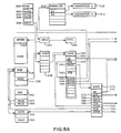
- user blocks are FRB 300, PARMLIST 310, and PARAMETERS 312, 314.
- MVS 50 blocks are PSA 350, TCB 324, ASCB 360, and SSAT 328. The remaining blocks pertain to DBMS 70.
- Function request block (FRB) 300 includes fields PARM 302, FVLE 304, RALE 306, and RHPC 308.
- RHPC 308 links FRB 300 to ERLY 322, which points (indirectly through other blocks) to Directory 560 (See Figure 9), and to the program request handler 320.
- FRB 300 will be copied into program request handler work area 330, where as FRB 340 it provides PARM linkage 342 to parameter list (PARMLIST) 310, FVLE 344 linkage to ASE 470, and RALE 346 linkage to RALE (including ERMID 432, ERMUS 434, and EFVL 436).
- PARMLIST 310 provides pointers P1, P2 to parameters 312, 314, respectively.
- Program request handler work area includes EB pointer 332 to EB 400, FRB 334 pointer to FRB 340, and AGNT pointer 336 to AGNT 370.
- ERLY 322 also provides linkage to the SSAT 328 entry which points to PRHW 330.
- Agent block 370 includes EB pointer 372 to execution block 400, ACE pointer 374 to agent control element 450, a collection of flags 386, ASID field 388, CCB pointer 390 to composite capabilities block 460, PRHW pointer 392 to PRHW 330, TCB pointer 394 to task control block 324, and ASCB pointer 396 to address space control block 360.
- TCB 324 includes SSAT pointer 326 to subsystem affinity table 328, and ASCB 360 includes address space identifier field 362.
- Prefix save area PSA 350 includes pointers TOLD 352 to the old task 324, and AOLD 354 to the old address space 360.
- Execution block 400 includes pointer ROB 402 to request option block ROB 410, and a collection of flags 404.
- ROB 410 includes ACE pointer 412 to agent control element 450.
- ACE 450 includes flags field 454, and pointers EBA 452 to execution block 400, RAL 456 to resource access list 420, RALE 458 to currently active resource access list entry (RALE) including ERMID 432, ERMUS 434, and EFVL 436, ASE 462 to agent status element ASE 470 and CCB 464 to composite capabilities block CCB 460.
- RALE currently active resource access list entry
- Resource access list RAL 420 includes in a header flags fields 422 and pointer field ACE 424 to agent control element 450, and a plurality of resource access list entries (three being shown), each with an ERMID, ERMUS, and EFVL field.
- EFVL 438, 436 pointers link RAL 420 to a plurality of function vector lists 448, 440.
- Each FVL 448, 440 includes a plurality of function vector lists entries, one for each SOP 480 associated with the function.
- Agent status element ASE 470 includes pointer fields ASE 472 pointing to ASE 470 and RAL 474 pointing to resource access list 420.
- Composite capabilities block CCB 460 includes a user identifier field (USER) and RESNM 466, NID 468, and CORID 469 fields.
- RESNM 466 names a plan, which names the data bases 76 the user is authorized to access.
- the linkage through the blocks illustrated in Figure 8 is as follows in order to validate an ACE: PSA 350 to TCB 324 to SSAT 328 with ERLY 322 to PRHW 330 to EB 400 to ROB 410 to ACE 450.
- the ACE is validated back to AGNT 370 to TCB 324 and ASCB 360.
- the linkage is as follows: ACE 450 and FRB 340 to RALE 436 to FVL 440 field named by FRB (FVLE 344) to SOP 480.
- ASEs 470 hold pushed down allocations which will be reinstated when the current level terminates.
- Agent control element (ACE) 450 represents a recoverable or nonrecoverable unit of work (that is, an agent) in subsystem 70.
- ACE 450 is the focal point for the resource and process control structures associated with an agent. These structures describe the resource and execution status of the agent at any given time.
- ACE 450 is a global construct and exists for the life span of the agent.
- EBA field 452 is the EB chain anchor.
- RAL 456 provides the address of execution time resource access list created by allocation control.
- CCB 464 provides the address of the CCB 460 representing the current capability.
- RALE 458 gives the address of RALE while an execution unit is within an RARQ linkage request, set on entry and reset on exit.
- Agent control block (AGNT) 370 is used to keep track of allied agents at the identify, signon, and create thread levels.
- EB 372 is a pointer to the associated execution block 400.
- ASID 388 is the address space ID of the allied agent.
- FLGS 386 include agent in-doubt status bits indicating that in-doubt status is, inter alia, resolved or insure-commit.
- the other fields are pointers to related blocks, as shown in Figure 8.
- Agent parameter list (APL) 570 is a parameter list indicating certain processing characteristics and resources associated with an allied agent. This list is input to both the create allied agent function and to the allocation control function of ASMC.
- ACHR field 571 includes a flag indication that the current agent structure should be reused, or a new agent structure created.
- ACE field 573 provides flags to be moved to the ACE 450 indicating that the ACE is created by create thread (CTHD) or by IDEN or SIGN.
- APLE 580 represents a repeating group, with each entry naming a resource to be allocated to the allied agent and the RMID of the manager of that resource.
- Agent status element (ASE) 470 represents agent status saved as a result of a create allied agent request. This block is chained LIFO from the field ASE 462 in ACE 450. ASE 472 is the chain field, and is anchored in associated ACE 450 to ASE 462. RAL pointer 474 is the initial RAL 420 address. This field is propagated to each ASE 470 on the ASE chain.
- Composite capabilities block (CCB) 460 contains information related to an allied agent. USER is the user identifier of the allied request. RESNM 466 is the resource name, or plan name. NID 468 is the network identifier, and CORID 469 is the correlation ID.
- Execution block (EB) 400 represents an execution unit associated with an agent, with an EB 400 for each agent.
- ACE 450 contains the first, or primary, EB for the agent. Subsequent EBs needed for synchronous, asynchronous, and/or cross memory services may result in a new execution unit being allocated to the agent. Each new execution unit is represented by another EB 450 chained from ACE 450.
- An EB 400 is a DBMS.70 construct, whereas an execution unit (TCB or SRB) is an MVS 50 construct.
- ROB 402 is the address of the ROB 410 associated with this execution unit.
- FLGS 404 indicate various status conditions, such as EB is primary or secondary; execution unit owns log read cursor; TCB mode execution unit; SRB mode execution unit; trace currently in control; purge stack required; execution unit awaiting termination of a synchronous unrelated execution unit; address space control task; service task controller task; recovery control task; service task; allied task; application in control of updates; DBMS 70 is in control; synchronize with termination.
- Function request block (FRB) 300 is used for communication between an application and DBMS 70.
- PARM 302 is the parameter list 310 address.
- FVLE 304 is the FVLE number within FVL 440.
- RALE 306 is the RALE 430 number.
- RHPC 308 is the program request handler PC number.
- Program request handler work area (PRHW) 330 provides a save area for PRHO 320 (Table 20) and the function-dependent program request handlers that it invokes.
- EB 332 is a pointer to the associated execution block 400.
- FRB 334 is a pointer to the key 7 FRB 340 within PRHW 330.
- AGNT 336 is a pointer to the associated agent control block 370.
- Resource access list (RAL) 420 is a mapping macro which contains linkage information to resource manager routines (SOPs) which process application program requests (GORs).
- FLGS 422 contain flags from SAED 600 HDRF field 622.
- ACE 424 is a pointer to ACE 450.
- RALEs 430 includes ERMID 426, 432, the RALE identifier; ERMUS 428, 434, the resource manager usage; and EFVL 436, 438, the FVL 448, 440 pointer.
- SAED 600 is invoked to create a static local SSAM entry in an APL 570.
- the invoked form of APL is used by resource manager SSAM to create descriptors in its directory 560.
- SAED 600 is included to map the SSAM entry 584 in an APL 570.
- APL 570 is a parameter list that contains one entry for each resource manager that supports allocation for the corresponding allied agent.
- SAED is the SSAM entry in APL 570.
- NDX 602 is the index in FVL 650 of the program call (PC) number for the related SOP 660.
- PC 604 is the PC EX (Entry Index) of the PC number.
- the LX (Linkage Index) portion of the PC number is assigned during initialization of DEMS.
- APLF 620 contains the APL 570 flags.
- HDRF 622 are the RAL 420 header flags 422, and RMUS 624 contains the RALE 430 user flags RMUS 434.
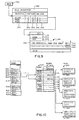
- Directory 560 is used to perform or guide allocation requests. Access to directory 560 is by way of ERLY block 322.
- Directory 560 includes protocol name fields 590, generic operation request (GOR) fields 592, resource name (plan) parameter field 594, indoubt resolution parameter field 596, and pointer field 566.
- Directory 560 protocol names include BATCH, SASS and MASS. (Not in Table 21). For each, the valid combinations for GOR field 592, RNP field 594, and IRP field 596 are given in Table 21.
- the DIR 1 NAME is the concatentation of fields 590, 592, 594, and 496;
- Table 21A gives for each valid DIR 1 NAME the allocation processing flags and persistent flags which become part of the environment.
- the abbreviations used for these flags are named.
- the various field values shown in Figure 9 are, for GOR 592: I (IDEN), S (SIGN), C (CTHD), and b (blank); for RNP 594: Y (yes, allow normal two phase commit with the requestor as coordinator), N (no, no support for resolution, allow SYNC only), b (blank, take default, which varies by protocol), and Q (inquiry, read only).
- a pointer 566 is provided for each valid combination of protocol name, GOR, RNP and IRP, with each pointer linking to a separate allocation parameter list (APL) 570.
- An APL 570 is provided for each valid state within each protocol, and includes a header portion having ACHR flags 571 and ACE flags 573 and an entry (APLE) portion 580.
- ACHR 571 flags are used to control the allocation process as it reuses or creates agent structures.
- Flags ACE 573 identify if the requestor is at the thread level (application state) and will be moved into ACE 450.
- SSAM 73 is an example of a resource manager (as that term is defined and used in the above referenced Jenner application).
- Each APL 570 includes in APLE 580 for each resource manager 584, 586, 583 an SSAM agent parameter list entry descriptor (SAED) 582, an example of which for IDEN state for MASS or SASS is illustrated in Figure 10.
- SAED SSAM agent parameter list entry descriptor
- SAED 600 illustrates the SAED entry 582 for resource manager SSAM for MASS or SASS protocol 590, for GOR 592 of I.
- SAED 600 includes entries for seventeen GOR/SOP pair descriptors, each pair including a NDX entry and a PC entry. These entries provide linkage to SOPs 660 through function vector list 650.
- the authorized GORs are TERM, SIGN, RIUR, and EXIT, and these are shown linked to SOPs 662, 664, 665, and 667, respectively. All unauthorized GORs are linked to SOP 666, the not supported processor, which ABENDs the requestor.
- function vector lists 700, 720, 740, and 760 are shown illustrating GOR/SOP pairs for other protocols and allocation levels.
- TERM GOR 701 is linked to SOP ID80 780 SIGN GOR 703 to SOP S130, RIUR GOR 705 to SOP RIAO 786, and EXIT GOR 711 to SOP EXTO 790.
- the GOR/SOP pairs for batch protocol at identified state, for MASS protocol at signed on state, and for MASS protocol at create thread state are similarly illustrated.
- the various SOPs 780-804 are described in Tables 1-18. Table 21 provides a description of all valid SAEDs for one implementation of this aspect of the invention.
- SIGN is implemented three times, as S130, S131, and S132. At each level, the work to perform to do the signon function is very different, so separate SOPs 784, 796, and 798 are provided. SIGN is not allowed for BATCH users, with any attempt to execute such being abended by not supported SOP 782.
- CTHD is supported directly for the identify state for BATCH protocols and only from the signed-on state for MASS protocol, with the same SOP CT30 788 invoked for both.
- TERM processing is implemented three times: CT80 has variations based on environmental flags which make certain options illegal under some protocols and create thread environments. Identified state TERM for BATCH and MASS protocols are both supported by the same processor SOP ID80 780.
- the SOP has a significant amount of subsystem 70 functions, and it is most efficient to keep BATCH and MASS protocols together and test flags to modify process flow.
- RIUR is supported only for coordinator TCBs at the identified level. All other attempts to execute RIUR abend in not supported SOP 782.
- SOPs which do allocation of functions include ID30, S130, CT30 (each invoking AMOO) and S132, which does allocation of database records based on user identifier.
- SOPs which do deallocation include CT80, S180, and ID80 (each of which invoke DM00). Other SOPs operate under only one allocation and change non-allocation parts of the execution environment.
- SSAM 73 executes module PRH 192, and lines 27 and 28 issues a program call to get to supervisor state and pass control to module PRHO 194.
- PRH module 192 acts as a buffer between the user (who must link-edit this module 192 with the program 190 requesting subsystem 70 functions) and the real subsystem 70 modules (Tables 1-18) that process these functions (GORs), as is set forth in Table 19.
- PRH 192 expects a standard parameter list, with the first parameter the function request block (FRB) 300, which it will pass to program request handler 194 (shown as 320 in Figure 8A) via program call RHPC 308
- PRHO module 194 (320) determines whether subsystem 70 is operational; invokes the correct program request handler, or error translator, or issues RARQ directly based on FRB 300 contents and the state of subsystem 70; manages serialization of agent 370, as set forth in Table 20.
- PRHO 194 (320) examines ERLY 322, PSA 350, TCB 324, and ASCB 360 to find SSAT 328 slot to get to PRHW 330 for the requesting user 190.
- FRB 300 is copied into PRHW 330 at 340, which is a DBMS 70 frozen copy of FRB 300 in the key of DBMS 70 to prevent the user from changing its FRB between validation and use.
- RALE index 346 is used to select EFVL 436, FVL 440, and FVLE 344 is used to compute the slot within FVL 440 to issue the program call contained therein to get to SOP 480. This linkage structure is traversed for every request except IDEN for any function.
- IDEN examines ERLY 322, PSA 350, TCB 324 and ASCB 360 and builds PRHW 330, fills in SSAT 328, builds AGNT 370 and CCB 460. It then goes to directory 560 ( Figure 9) to get the appropriate APL 570, and invokes allocation router (create allied agent ASMC) 197 to build an allied agent structure, which includes EB 400, ROB 410, RAL 420, and ACE 450 using APL 570. Router 197 then invokes each resource manager identified by RMID 584, passing related parameters 582 with which those resource manager routines will build the FVLs 448, 440 as appropriate.
- Module AMOO creates FVL 652 based on specific contents of SAED 600 contained within the selected APL 570.
- the ABRT GOR 640 is not supported at this protocol at the identified state, while SIGN and RIUR are. Processing now waits for the next call from the user, which may be SIGN.
- a user request for SIGN navigates under the control of PRHO 194 and SOP 480 (662) the blocks built by IDEN.
- SIGN is invoked if and only if authorized, as is shown by FVL 652 for the invoking users current allocation level.
- specific signon processor SOP 662 constructs name 590, 592, 594, 596, which selects by pointer 566 the APL 570 appropriate to this request.
- APL 570 is given to create allied agent 207 which will create ASE 470 containing old RAL 420; update RAL 420 and ACE 450 with information from APL 570; invoke each resource manager 583, 584, 586 passing parameters 582.
- Each resource manager builds an FVL from this new level of allocation.
- SAED 582, 600 builds FVL 652 by invoking AMOO.
- Figure 7 illustrates, inter alia, a signed on MASS 740.
- Functional capability represents the current capability of a user 80-85 of subsystem 70. It describes completely the functions provided to the user and provides linkage to all generic operation requests (GORs) 640 allowed at the current allocation level, or state (100-148) for a given access protocol 590.
- GORs generic operation requests
- the functional capability of a user is represented by the following:
- Access protocol name 590 is used to construct the name used to access the allocation descriptor APL 570 which was used to create this functional capability. It will be used by all subsequent allocation specific operation processors SOPs 660 in processing requests. This value never changes after the first allocation is performed and the initial functional capability is built.
- Access protocol name 590 in the preferred embodiment, is a parameter on IDEN and will be either BATCH, SASS, or MASS, depending on the particular connection involved.
- Capability characteristics are copied from the allocation descriptor into the functional capability when a successful allocation process occurs. These characteristics indicators show directly the key features of the latest allocation such that all specific operation processors (SOPs) implementing generic operation requests (GORs) at this allocation level may adjust their processing appropriately. These indicators allow for interpretation of the invoker's condition when interpretation is desired. The interpretation of these characteristics indicators must be consistent between all SOPs which might operate at any given allocation level. Capability characteristics are maintained in agent control element ACE 450 and the resource access list 420 header. These indicators show all DBMS 70 SOPs 480 the characteristics of the currently allocated and executing application program. The interpretation of these characteristics indicators is consistent between all SOPs 480.
- One such indicator is the "subsystem” indicator used by the data base manager 74 in determining the correct action for its commit requests. This indicator is set whenever the currently allocated thread supports recovery indoubt resolution, DBMS 70 cannot unilaterally act on any commit request.
- Another such indicator is the "subject to user interruption” indicator used by all DBMS 70 resource managers which perform must complete operations. This characteristic is common to all allocation levels for the BATCH access protocol.
- the generic operation-specific processor list is information copied from the allocation descriptor into the functional capability when a successful allocation process occurs. This lists all generic operation requests (GORs) the requestor will be allowed to issue after processing of the current request is completed. It also associates specific operation processors (SOPs) to process each of the GORs the requestor is allowed to use at the new allocation level under his access protocol. This allows a completely different SOP to provide support for each different allocation level (state) and access protocol for which the GOR is valid. In this case, no interpretation would be required to determine the requestor's characteristics. GORs not listed in the GOR/SOP paris list are associated with the not supported, or unauthorized SOP. There is no GOR which relates directly to the not supported SOP.
- the functional capability is produced by an allocation GOR processed by an allocation SOP.
- the GOR/SOP pairs list is contained in the resource access list entries (RALEs) 430 and in the function vector lists (FVL) 448, 440, 700, 720, 740 connected to those RALEs.
- RALEs resource access list entries
- FVL function vector lists
- the RALE/FVLE combination is used in DBMS 70 linkage to enforce valid entry to the allocated (and only the allocated) SOPs 480.
- the first functional capability is built by the IDEN operation processor (SOP).
- the SIGN and CTHD allocation SOPs initiate additional allocations creating new functional capabilities and new allocation levels (states 100-148). All components of DBMS 70 have an opportunity to contribute to the functional capability by setting up RALE-FVLE information during an internal allocation process.
- system linkages Prior to entry to the allocation specific operation processor, system linkages must have insured that this is a proper (authorized) invocation. For unauthorized requests, the not supported SOP should have been invoked or a program check should have occurred.
- the allocation SOP first assembles the name of the allocation descriptor from the access protocol name, the name of the allocation GOR this allocation SOP is supporting, and the parameters provided by the requestor. An attempt to access the allocation descriptor is then made. If nothing is returned for the developed name, the request must be invalid (syntax error). The requestor is so informed and the allocation SOP does not proceed with allocation. If an allocation descriptor is returned, the indicated environmental checks are performed by the allocation SOP. If any of the prerequisites are not met, the requestor is so informed and the allocation SOP does not proceed with allocation. When all prerequisites are met, the allocation SOP will complete the allocation process, update the functional capability with the information in the allocation descriptor and return to the caller.
- the allocation SOP is completely insensitive to what has been allocated.
- the allocation SOP operates as a list processor, updating the functional capability with the information contained in the allocation descriptor. Processing of this request may have caused allocation of additional allocation GORs or it may not have. Even if exactly the same GORs are allocated at the new allocation level (state) the set of SOPs supporting those GORs may be completely different.
- Each allocation is independent. Each allocation is a complete allocation.
- Each GOR is reallocated to some SOP (possibly "not supported") and old allocations (the previous allocation levels) are hidden from access. When the new allocation level is removed, the previous allocation level and GOR set will again be available to the user from the ASE queue 470.
- SSAM 73 invokes an internal service to let all DBMS 70 resource managers know of the new allocation. These resource managers build RALEs 430, FVLEs 446 and whatever else is required to update their piece of the functional capability.
- the SSAM SIGN GOR is a good example of one which changes at each level.
- the signed-on state 124 SIGN SOP is not an allocation SOP at all-it merely records the new user ID.
- the SIGNSOP at the application state is yet another completely different processor-it must verify that the new user is allowed to operate the same way the current user is performing. This last switch in processing function was performed by the CTHD allocation SOP without participation of the SIGN SOP, without adding any requirement to the SIGN SOP to interpret where it is before it processes its next request, and without any specific support by the CTHD allocation SOP.
- the key used to access allocation descriptors includes (1) access protocol name, (2) generic operation name, and (3) encoded parameter values. In the embodiment described, this key is the concatenation of fields PROTOCOL 590, GOR 592, RNP 594, and IRP 596. This key yields a pointer 566 to an APL 570 which is used to generate the allocation descriptor.
- the allocation descriptor includes (1) prerequisite conditions tests, (2) capability characteristics, and (3) GOR/SOP pair listings.
- the encoded parameter values are encoded by the allocation SOP as follows: for finite value parameters (yes, no, or other multiple choice), the parameter value provided with the invocation of the allocation SOP is encoded or copied into the key. For other parameters (where there are too many valid parameter values), the presence or absence of the parameter is encoded into the key. This encoding must be consistent between all SOPs which implement any single GOR. Since the allocation GOR name 592 is also part of the allocation descriptor address, there is no requirement that the encodings be consistent across GORs. The omission of a parameter is indicated by a specific coding (b) of the allocation descriptor address (fields 592, 594, 596). The access protocol name 590 is part of the allocation descriptor address.
- the value of indoubt resolution (IRP) 596 ("Y", yes the requestor subsystem will support indoubt resolution; "N", no it will not; or "b", not specified) is encoded into the allocation descriptor name.
- the default for the BATCH access protocol 590 is No (in fact, Yes is illegal) and for the subsystem type connections (SASS and MASS), the default is Yes.
- the presence or absence of the resource name parameter (RNP) 594 is encoded as a Y or N. This causes selection of different allocation descriptors, which cause different allocations to occur.
- the data base manager DBM 74 is provided the name of a default application plan when no resource name 594 is provided (See Table 21).
- Capability characteristics indicate to all SOPs implementing GORs at this allocation level (state) the characteristics of the currently allocated capability under this access protocol 590. The interpretation of these characteristics indicators is consistent between all SOPs which might operate at any given allocation level.
- GOR/SOP pairs listings 600 lists all GORs 640 the requestor will be allowed to issue after processing of the current request is completed. It also associates specific SOPs to process each of the GORs the requestor is allowed to use at the new allocation level under his access protocol. GORs not listed are associated with the "not supported" SOP 666.
Claims (9)
Applications Claiming Priority (10)
| Application Number | Priority Date | Filing Date | Title |
|---|---|---|---|
| US39045482A | 1982-06-21 | 1982-06-21 | |
| US05/390,163 US4648031A (en) | 1982-06-21 | 1982-06-21 | Method and apparatus for restarting a computing system |
| US390163 | 1982-06-21 | ||
| US06/390,485 US4507751A (en) | 1982-06-21 | 1982-06-21 | Method and apparatus for logging journal data using a log write ahead data set |
| US390485 | 1982-06-21 | ||
| US390454 | 1982-06-21 | ||
| US391629 | 1982-06-24 | ||
| US06/391,629 US4509119A (en) | 1982-06-24 | 1982-06-24 | Method for managing a buffer pool referenced by batch and interactive processes |
| US39324482A | 1982-06-29 | 1982-06-29 | |
| US393244 | 1982-06-29 |
Publications (3)
| Publication Number | Publication Date |
|---|---|
| EP0097258A2 EP0097258A2 (fr) | 1984-01-04 |
| EP0097258A3 EP0097258A3 (en) | 1987-10-14 |
| EP0097258B1 true EP0097258B1 (fr) | 1990-03-14 |
Family
ID=27541422
Family Applications (1)
| Application Number | Title | Priority Date | Filing Date |
|---|---|---|---|
| EP83105178A Expired - Lifetime EP0097258B1 (fr) | 1982-06-21 | 1983-05-25 | Equipement de calcul et son procédé d'exploitation |
Country Status (2)
| Country | Link |
|---|---|
| EP (1) | EP0097258B1 (fr) |
| DE (1) | DE3381324D1 (fr) |
Families Citing this family (2)
| Publication number | Priority date | Publication date | Assignee | Title |
|---|---|---|---|---|
| GB2166572A (en) * | 1984-11-02 | 1986-05-08 | Sadleir Computer Res Ltd | Data processing system |
| US4713753A (en) * | 1985-02-21 | 1987-12-15 | Honeywell Inc. | Secure data processing system architecture with format control |
-
1983
- 1983-05-25 DE DE8383105178T patent/DE3381324D1/de not_active Expired - Fee Related
- 1983-05-25 EP EP83105178A patent/EP0097258B1/fr not_active Expired - Lifetime
Also Published As
| Publication number | Publication date |
|---|---|
| DE3381324D1 (de) | 1990-04-19 |
| EP0097258A2 (fr) | 1984-01-04 |
| EP0097258A3 (en) | 1987-10-14 |
Similar Documents
| Publication | Publication Date | Title |
|---|---|---|
| US5872971A (en) | Data processing systems and methods providing interoperability between data processing resources | |
| Chin et al. | Distributed, object-based programming systems | |
| CN100498699C (zh) | 在运行时系统中共享对象 | |
| CN1989489B (zh) | 数据处理方法和装置 | |
| US6138120A (en) | System for sharing server sessions across multiple clients | |
| US4399504A (en) | Method and means for the sharing of data resources in a multiprocessing, multiprogramming environment | |
| CN1989488B (zh) | 运行时系统的鲁棒共享 | |
| US5095421A (en) | Transaction processing facility within an operating system environment | |
| US8103779B2 (en) | Mechanism for enabling session information to be shared across multiple processes | |
| US6256637B1 (en) | Transactional virtual machine architecture | |
| US20070203910A1 (en) | Method and System for Load Balancing a Distributed Database | |
| EP0272836A2 (fr) | Commande d'équilibrage dynamique de charge pour un système multiprocesseur | |
| US6178440B1 (en) | Distributed transaction processing system implementing concurrency control within the object request broker and locking all server objects involved in a transaction at its start | |
| EP0817017A2 (fr) | Système d'interfaces entre programmes d'application | |
| US6892202B2 (en) | Optimistic transaction compiler | |
| US7058656B2 (en) | System and method of using extensions in a data structure without interfering with applications unaware of the extensions | |
| US6542922B1 (en) | Client/server transaction data processing system with automatic distributed coordinator set up into a linear chain for use of linear commit optimization | |
| US6430638B1 (en) | Thread synchronization via selective object locking | |
| JPH09171473A (ja) | エラーを管理するための方法およびデータ処理システム | |
| EP0097258B1 (fr) | Equipement de calcul et son procédé d'exploitation | |
| Kim et al. | A database server for distributed real-time systems: Issues and experiences | |
| Blackman | IMS celebrates thirty years as an IBM product | |
| Pliner et al. | A Distributed Data Management System for Real-Time Applications | |
| Pohl | MERCURY: a real-time message management facility for distributed cooperative computing environments | |
| Turton | The management of operating system state data |
Legal Events
| Date | Code | Title | Description |
|---|---|---|---|
| PUAI | Public reference made under article 153(3) epc to a published international application that has entered the european phase |
Free format text: ORIGINAL CODE: 0009012 |
|
| AK | Designated contracting states |
Designated state(s): DE FR GB |
|
| PUAL | Search report despatched |
Free format text: ORIGINAL CODE: 0009013 |
|
| AK | Designated contracting states |
Kind code of ref document: A3 Designated state(s): DE FR GB |
|
| 17P | Request for examination filed |
Effective date: 19840426 |
|
| 17Q | First examination report despatched |
Effective date: 19880713 |
|
| GRAA | (expected) grant |
Free format text: ORIGINAL CODE: 0009210 |
|
| AK | Designated contracting states |
Kind code of ref document: B1 Designated state(s): DE FR GB |
|
| REF | Corresponds to: |
Ref document number: 3381324 Country of ref document: DE Date of ref document: 19900419 |
|
| ET | Fr: translation filed | ||
| PLBE | No opposition filed within time limit |
Free format text: ORIGINAL CODE: 0009261 |
|
| STAA | Information on the status of an ep patent application or granted ep patent |
Free format text: STATUS: NO OPPOSITION FILED WITHIN TIME LIMIT |
|
| 26N | No opposition filed | ||
| PGFP | Annual fee paid to national office [announced via postgrant information from national office to epo] |
Ref country code: FR Payment date: 19910430 Year of fee payment: 9 |
|
| PGFP | Annual fee paid to national office [announced via postgrant information from national office to epo] |
Ref country code: DE Payment date: 19910525 Year of fee payment: 9 |
|
| PGFP | Annual fee paid to national office [announced via postgrant information from national office to epo] |
Ref country code: GB Payment date: 19920409 Year of fee payment: 10 |
|
| PG25 | Lapsed in a contracting state [announced via postgrant information from national office to epo] |
Ref country code: FR Effective date: 19930129 |
|
| PG25 | Lapsed in a contracting state [announced via postgrant information from national office to epo] |
Ref country code: DE Effective date: 19930202 |
|
| REG | Reference to a national code |
Ref country code: FR Ref legal event code: ST |
|
| PG25 | Lapsed in a contracting state [announced via postgrant information from national office to epo] |
Ref country code: GB Effective date: 19930525 |
|
| GBPC | Gb: european patent ceased through non-payment of renewal fee |
Effective date: 19930525 |