EP0096937A1 - Method of preventing overloading of the central controller of a telecommunication system and arrangement for performing the method - Google Patents
Method of preventing overloading of the central controller of a telecommunication system and arrangement for performing the method Download PDFInfo
- Publication number
- EP0096937A1 EP0096937A1 EP83200838A EP83200838A EP0096937A1 EP 0096937 A1 EP0096937 A1 EP 0096937A1 EP 83200838 A EP83200838 A EP 83200838A EP 83200838 A EP83200838 A EP 83200838A EP 0096937 A1 EP0096937 A1 EP 0096937A1
- Authority
- EP
- European Patent Office
- Prior art keywords
- period
- calls
- call
- central controller
- determined
- Prior art date
- Legal status (The legal status is an assumption and is not a legal conclusion. Google has not performed a legal analysis and makes no representation as to the accuracy of the status listed.)
- Granted
Links
Images

Classifications
-
- H—ELECTRICITY
- H04—ELECTRIC COMMUNICATION TECHNIQUE
- H04Q—SELECTING
- H04Q3/00—Selecting arrangements
- H04Q3/42—Circuit arrangements for indirect selecting controlled by common circuits, e.g. register controller, marker
- H04Q3/54—Circuit arrangements for indirect selecting controlled by common circuits, e.g. register controller, marker in which the logic circuitry controlling the exchange is centralised
- H04Q3/545—Circuit arrangements for indirect selecting controlled by common circuits, e.g. register controller, marker in which the logic circuitry controlling the exchange is centralised using a stored programme
- H04Q3/54575—Software application
- H04Q3/54591—Supervision, e.g. fault localisation, traffic measurements, avoiding errors, failure recovery, monitoring, statistical analysis
Landscapes
- Engineering & Computer Science (AREA)
- Computer Networks & Wireless Communication (AREA)
- Exchange Systems With Centralized Control (AREA)
- Monitoring And Testing Of Exchanges (AREA)
Abstract
Description
- The invention relates to a method of preventing overloading of the central controller of a telecommunication system, more specifically a telephone exchange of the type commonly referred to as the stored program controlled (SPC) type.
- The invention further relates to an arrangement for performing the method.
- In the present telecommunication systems some provisions are of a common and centralized construction, so that only limited numbers of these systems are sufficient. This imposes restrictions on the processing capacity of the system. In systems which comprise a central controller, use is made of the central processor for all connections and connection requests. Owing to the limited quantity of processor time queues of, for example, telephone tasks are formed. In the event of growing waiting times the required response time can no longer be satisfied, while in the most serious case calls will fail. As processor time is also consumed by unsuccessful calls, the number of successfully processed calls will decrease even further.
- In order to avert an imminent overloading of the central controller it is known to predict the number of calls which may be accepted in a subsequent period on the basis of tl-P processor load in a preceding period and the number of calls accepted in that preceding period. In order to prevent excessive fluctuations caused by fluctuations in the number of calls, a limit is imposed on the increase or decrease, as the case may be, of the number of calls which may be accepted in the subsequent period. Owing to the inertia of this control the processor capacity is not optimally utilized and that more specifically at the instant at which this capacity is required to its full extent.
- It is an object of the invention to provide a method of preventing overloading of the central controller by means of which in a simple, fast and reliable way an imminent overload is detected and thereafter averted, and by means of which the lowest possible number of calls are refused.
- According to the invention, the method of preventing overloading of the central controller is characterized in that the method comprises the following steps:
- 1. the determination of the number of calls which were in the process of being set-up in a first period of a predetermined duration;
- 2. the determination of the total demand on the capacity of the central controller in the said first period by the number of calls in the process of being set-up determined in
step 1, and the remaining tasks of the central controller; - 3. the estimation of the maximum number of calls which can be in the process of being set-up at a maximum load of the central controller in a second period of a predetermined duration;
- 4. the determination for each newly offered call in the said second period whether thereby the instantaneous number of calls in the process of being set-up reaches the maximum number estimated in step 3;
- 5. accepting the offered call if and for so long as the number estimated in step 3 has not been reached;
- 6. rejecting the prevented call if this was the case;
- 7. repeating the
steps 1 to 6, inclusive in a subsequent first period for calls to be offered in a next second period. - By means of this method it is accomplished that substantially no offered calls need beurefused unnecessarily by the exchange.
- It is advantageous if consecutive first periods partly overlap each other, the method preferably being performed such that the said first period consists of k (k ) 2) sub-periods, that in each sub-period the number of calls in the process of being set-up determined in
step 1 and the total of the demand on the central controller capacity determined in step 2 and the estimation effected in step 3 are based on the k results in the k sub-periods. This accomplishes that on the one hand, during a relatively long first period, and consequently reliably, the number of calls in the set-up phase can be measured k times and on the other hand sudden increases in the traffic offered can be rapidly passed on. Thus it has been found that a first period having a duration of 4 sec. which always shifts 1 sec. and is divided into 4 sub-periods is a suitable choice for telephone xchanges of the SPC type. - In addition to sudden increases in the traffic offered which is responded to in the above-described way, sudden increases in the load of the central controller may also occur as a result of tasks which are not closely associated with a call: for example owing to the commencement of a traffic measuring program. The accompanying sudden load increase is generally much steeper than the sudden increase in the traffic offered. Therefore it is advantageous that, if the number of calls in the process of being set-up and/or the total of the demand is significantly higher in the k sub-period than in the preceding (k-1) sub-period or if the maximum has been reached, as the case may be, no setting-up of offered calls is started in the subsequent second period.
- The load on the central controller is determined in a simple way when the determination of the total demand on the capacity of the central control to be determined in step 2 is effected by subtracting the measured capacity spent on idle jobs from the maximum capacity.
- It is further advantageous if the number of calls which are in the process of being set-up to be determined in step 2 is effected by balancing, in a second period of time having a predetermined duration the calls in the process of being set-up, the calls of which the set-up is started and the calls which have been processed.
- A further object of the invention is to provide an arrangement with which the method in accordance with the invention is performed in a simple way, which requires only a small load on the central controller. The arrangement for performing the method is therefore characterized in that it comprises a first storage arrangement for storing the value of the total demand on the capacity of the central controller in the first period, a second storage arrangement for storing the value of the number of calls which are in the process of being set-up in the first period, a first arithmetic unit for determining from the values recorded in the two storage arrangements the maximum number of calls which can be in the process of being set-up, a counter for counting the instantaneous number of calls in the process of being set up in a second period, a difference- producing unit for comparing the counting position with the maximum number of calls which can be in the process of being set-up, a change-over switch, an acceptance unit, a rejection unit and a call detector, that the change-over switch connects the acceptance unit to the call detector under the control of the difference- producing unit, that the acceptance unit is connected to an input of the counter for incrementing the counting position by one when a call is accepted, that an output of the counter is connected to an input of the second storage arrangement for recording in or at the end of the second period the counting position and that the arrangement further comprises means connected to an input of the first storage arrangement for determining the total of the demand on the capacity of the central controller in the said second period.
- The invention and its advantages will now be further described by way of example with reference to the drawing. Therein
- Fig. 1 shows the load on the processor of the central controller as a function of the number of calls in the process of being set-up;
- Fig. 2 shows a time diagram to illustrate the choice of the periods in the method in accordance with the invention;
- Fig. 3 shows a schematic representation of an arrangement for performing the method in accordance with the invention and
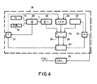
- Fig. 4 shows a schematic representation of an alternative for the second arithmetic unit for use in the arrangement according to Fig. 3.
- In telecommunication systems which comprise a central controller, a processor which forms prt of the central controller is used for making, maintaining and breaking connections. In automatic telephone exchanges of the stored program controlled (SPC) type signalling, path searching, metering, and observation of the traffic for error detection, that is telephony tasks in a narrow sense, are performed by the central control. In addition, the central controller also performs tasks of an administrative nature, (for example making operative or blocking, as the case may be, subscriber's connections) in the field of supervision (locating errors, processing errors), and measurements (for example traffic measurements). For economic reasons the central controller of such a size that the average load to be expected can be easily handled. However, in the event of peak loads overload may occur so that offered calls have to be refused. In addition, in such a situation long queues of telephony tasks for the processors occur as a result of which the requirements as regards response can also no longer be satisfied. As processor time is also spent on refused calls the number of successfully handled calls decreases.
- The invention provides a method of preventing overloading of the central controller. For that purpose the number of calls (CIB.) which were in the process of being set-up in a first period of a predetermined duration are determined. The determination thereof may be effected by counting how many calls were in the process of being set-up in the relevant period (for example on an average) or to estimate it by taking, in that first period, a sample of the calls which are at that moment in the process of being set-up.
- Thereafter the total of the demand on the capacity of the central controller is determined. This includes both the demand on the capacity for the calls being set-up and the demand on the capacity for the remaining tasks. This is measured by determining the complement, namely the number of what are commonly referred to as idle jobs performed in the relevant period.
- If a graph of the number of calls being set-up versus the load on the central controller L is plotted, then a relationship is found as shown in Fig. 1 (solid line). If no calls are in the setting-up phase, the load is equal to L , the what is commonly referred o to as the zero load. With an increasing number of calls in the process of being set-up the load increases substantially directly proportionally therewith until a maximum load L is reached. The number of calls max in the process of being set-up which are then processed is equal to CAL (call acceptance limit).
- Maximum load is here understood to mean that load of the processor at which all telephony tasks and other tasks are just performed within the required response times. This maximum load is generally lower than maximum loading of the actual processor and amounts to, for example, 90% of that value.
- The load line is not invariable but depends on a number of factors. If the zero-load becomes high, (for example due to the commencement of traffic measurements) then the load line will shift to higher load values (dashed line), which implies that the maximum number of calls which may enter the setting-up phase decreases. Likewise, the composition of the traffic offered (local, trunk calls, the what is commonly referred to as call mix) may be subjected to changes. For the load line this will have, for example, the consequence denoted by the dot-and-dash line in Fig. 1. The number of calls of which the set-up may be started becomes significantly larger in that case. It is therefore important to know how high the instantaneous load L. of the central controller is and with how i many calls in the process of being set-up CIBi that load occurs. By means of a second point (CIB., L.) in the graph the variation of the load line can be derived and from this it can be determined how many calls in the process of being set-up (CIB = CAL) are possible at a maximum load (L max ). By way of .second point the load at, for example, zero-load conditions can be determined (CIBj=O and Lj= L ). This might be done by measuring L . For the purpose of simplicity and in view of a low load for the central control, a fixed value for Lo and more specifically Lo = 0, has been opted for. The load line is assumed to pass as it were through the origin. An error is then indeed introduced in the calculated value of the call acceptance limit CAL but this error decreases versus an increasing load of the central control and is accurately zero if Li = L max The error is, however, of such a nature that the call acceptance limit value which is determined is on the low side so that an overload owing to this error is impossible.
- The call acceptance limit value is assumed to hold for a given future period, namely a second period of a predetermined value. Every offered call which reaches the central controller in this second period will increment the number of calls in the setting-up process by one. It is checked whether as a result thereof the call acceptance limit value is reached. If the total of the instantaneous number of calls being set up incremented by the actual call remains below said limit value then the call is allowed to enter the setting-up phase and the number of calls being processed is increased by one. If in contrast therewith the limit value is reached the call is rejected. Whether or not an offered call is accepted for setting up is made known to the subscriber by the customary, known handling procedure (for example by applying the dial tone or busy tone, as the case may be, to the subscriber set). All calls occurring in that second period are handled in this way. The possibility, after a call has been rejected, of having this call wait for a short period of time and then trying to reach acceptance once more thereafter may be considred. Namely, in that period of time the number of calls being processed may have decreased below the limit value because the setting-up of a number of calls has been completed in that period. The number of calls being set-up in the second period is the balance of the number of calls in the setting-up phase at the beginning of that second period, the number of calls which since then have entered the setting-up phase and the number of calls successfully handled.
- At the end of the second period the entire cycle is repeated for a subsequent continuous second period, however, with calculated-limited value. The manner in which this is effected is shown in Fig. 2 for three consecutive second periods. In the second period SP1 calls are accepted or rejected on the basis of the call acceptance limit value which is based on an estimation thereof performed on results which relate to a first period FP1. Likewise, the actual limit value in the subsequent second period SP2 is derived from the results in a subsequent first period FP2. For the third second period SP3 shown the limit value determined in the first period FP3 holds. Consecutive first periods FP partly overlap. This method has the advantage that the load (in the form of calls being processed) is measured over a comparatively long first period, causing fluctuations in this quantity to be averaged. Furthermore, real sudden increases in the load are rapidly responded to because of the fact that the periods are of a short duration and consequently succeed each other rapidly.
- In a practical embodiment of the method the duration of the first period is chosen to be 4 seconds and for the
second period 1 second, each first period overlapping the previous first period by 3 seconds. - In some situations it may be desirable to respond very rapidly to a sudden increase of the load. Thus, a duration of four seconds being chosen for a first period, in the first second after the occurrence of a sudden increase of the load only one quarter of that sudden load increase would be included in the determination of the call acceptance limit. If this is too slow the method can be adapted so that when in a sub-period (namely the last sub-period of the first period) the load amounts to 100% all the offered calls are rejected.
- An embodiment of an arrangement for performng the method of preventing overload from occurring is shown block-schematically in Fig. 3. The subscriber's sets T1, ... Tn are each connected to an
input circuit 11 of the telecommunication system via a two-way connection 10. The twr¡-way connection 10 is connected to acall detector 12 which is part of theinput circuit 11 and has for its object to detect when a subscriber makes a call. Theinput circuit 11 must have the ability to accept or reject the offered call. For that purpose the arrangement comprises the following means. The values of the total demand on the capacity of the central controller L in the preceding k sub-periods, namely Li, Li-1 Li-k+1 are stored in a storage arrangement 13, which comprises k storage locations. These k values form, as it were, the k samples of the capacity demand in a first period FP. A value Lj J which is representative of the load of the central controller, for example at the end of a sub-period j, is found by combining: the fraction Fj of the period j the central controller spends on idle jobs (or the number of idle jobs processed by the central processor) and the number of tasks Nj waiting at the end of the period j before the processor. The total of the demand on the capacity of the central controller Lj in the sub-period j is then
- In each sub-period j the value of F. and Nj are applied to
registers arithmetic unit 17, which calculates the value of Lj in accordance with formula (1). At the end of each sub-period j the value of L is written intostorage arrangement 13 at sub-period L.. This is effected in such a way that the most recently calculated value of L replaces the least recent value in thestorage arrangement 13. Consequently, thestorage arrangement 13 comprises always the k most recent values (samples) of the capacity demand L. Fig. 3 shows the values of j = i, i-1, ... i-k+ 1. - The k values of the number of calls being set-up CIB. in the last k sub-periods are present in
storage arrangement 14, which also comprises k locations. The values of CIB. in thestorage arrangement 14 relates to the same sub-periods as those of Lj instore 15. - A second
arithmetic unit 18 determines from the values stored in thestorage arrangement L i and the average number of calls being set up CIB.. Consequently:
- The call acceptance limit CALi is determined by the second arithmetic units from the formula:

- The load line (see Fig. 1) is in the present case the line through the points (0, L ) and (
CIB i ,L i ). The result of this calculation CAL., is written into 1register 19. - In addition, the arrangement comprises an (up/down) counter 20 for counting the number of calls being set-up. For that purpose the
counter 20 has afirst input 21 to which anacceptance unit 23 is connected for incrementing the counting position ofcounter 20 for each call which enters into the set-up phase. Thecounter 20 further has asecond input 22 for decrementing the counting position ofcounter 20 for each successfully processed call.Therefore, the counting position ofcounter 20 always shows the instantaneous value of the number of calls being set up. - If now a call is detected by
call detector 12, adifference unit 25 is activated viaconnection 24. - The
difference unit 25 compares the counting positions of counter 20 (CIB) applied to its input with the value (CALi) stored inregister 19. If CIB < CAL. then a control signal supplied by difference unit 25 (shown by means of a dotted line) adjusts a change-over switch 26 to the position 26-1. This results in theacceptance unit 23 reporting to the subscriber set T. viacall detector 12 that the offered call has been accepted and that its set-up is started. At the same time the acceptance unit increments the counting position by one viainput 21 ofcounter 20. If in contrast therewith CIB ≥ CALi then the change-over switch 26 is adjusted to the position 26-2 by a control signal supplied bydifference unit 25 and the rejection unit 27 reports to the subscriber set T. via thecall detector 12 that the offered call is refused. - The call acceptance limit CAL1 is valid during a second period of a predetermined duration. This limit is used for all calls offered in that period. In a subsequent second period a new value of CALi is used. The.number of calls being set up is determined in, or at the end of such a second period and applied to
storage arrangement 14 viainput 28 and then forms the most recent sample. Acting thus the number of calls being set up in that period partly determines the acceptance limit in the future k sub-periods. - If the last value of the load L. is a sudden peak then this may be sufficient cause, to create the possibility·of a rapid response to overload, not to accept new calls in the period i+1.
- It is alternatively possible to employ more refined methods such as for example linear regression instead of using the average value of CIB and L (
CIB i ,L i ) as the starting point. - In addition, as mentioned already in the foregoing it is useful for some applications to have new calls, when CIB ) CALi, wait a short period of time, as it is possible that in that period CIB becomes less than CAL.. In this way a still more exhaustive use of the processor of the central controller can be obtained.
- It may also be useful to have the acceptance of a call depend on the urgency, the importance etc. of the call. Calls which enter via trunk lines may, for example, be given a higher priority than calls coming directly from subscribers as the telecommunications system has invested more in the first-mentioned calls. This can be implemented by giving Lmax in formula (3) a higher value (Lmax, h) for calls having a higher priority than for calls having a lower priority (L max, 1). This implies that the second
arithmetic unit 18 determines two values for CALi, namely CALi (L max, h) and CALi(Lmax, I). Both values are applied to adifference unit 25. In the event that the acceptance of a call having a higher priority must be judged, then this is decided on the basis of the result of the equation

- This differentiation accomplishes a more economical use of the central controller.
- In a practical arrangement for performing the method k is equal to 4. It should be noted that the arrangement can be realised by means of universal sequential logic circuits such as commercially available microprocessors with associated stores and peripheral equipment. The processor of the central controller might be used to advantage for that purpose.
- As explained above, also in the case of sudden changes in the load the call acceptance limit can be adapted in a reasonably fast way to that new load value. If a still faster adaptation is required this is provxed in the following way.
- The second arithmetic unit of the arrangement shown in Figure 3 is arranged as shown in Figure 4.
- The
storage device 13 which may now consist of only one memory location contains the value of the total demand on the capacity of the central controller in the last sub-period, namely Li. In thestorage device 14 which may now also consist of only one memory location the value is stored of the number of calls in the process of being set-up CIBi in the last sub-period. The values stored in thestorage devices divider arrangement 23 for the determination of the quantity r. = Li/CIBi, i.e. the load of each call being set-up, and this value ri is added in theaccumulator 30 to the previous value of r. so as to obtain the sum
divider arrangement 29 has determined a new value of ri counter 31 is incremented one step. The instantaneous counter content forms the value of n. The anticipated value of the sum
- The anticipated value is determined by
multiplier 32, which for this purpose is connected to an output ofcounter 31 and to an output of astorage device 33 in which the present value of m has been stored. In addition, the second arithmetic unit comprises acomparison arrangement 34 having three inputs.Accumulator 30 is connected to a first input andmultiplier 32 is connected to a second input. A third input ofcomparison arrangement 34 is coupled to a further output ofstorage device 33 via athreshold value arrangement 35. - The
comparison arrangement 34 determines whether |
threshold value arrangement 35. If |

- In a first case a control signal is applied via a
first output 36 ofcomparison arrangement 34 to aconnection unit 37 which results in the present value of the average load per call being set-up (m) being incremented by dm, whereas in the second case a control signal is applied via asecond output 38 to the correction unit which results in m being decremented by dm. To that end, an output ofcorrection unit 37 is connected to a reset input ofcounter 31 for resettingcounter 31 earn time m is adapted (by +dm or -dm). Thus, theaccumulator 30 is reset to zero aNd the comparison arrangement thereafter determines a new sum
storage device 33 serves as a basis for the value of the call acceptance limit CALi which is stored in register 19 (CAL. = Li/m) and is employed in a manner described with reference to Figure 3 to determine whether new calls are accepted or not. - The threshold value generated by the threshold value arrangement has for its object to prevent frequent, useless adaptations of the call acceptance value and is, for example, chosen equal to

Claims (9)
Applications Claiming Priority (2)
| Application Number | Priority Date | Filing Date | Title |
|---|---|---|---|
| NL8202419A NL8202419A (en) | 1982-06-15 | 1982-06-15 | METHOD FOR PREVENTING OVERLOADING OF THE CENTRAL CONTROL OF A TELECOMMUNICATIONS SYSTEM AND APPARATUS FOR PERFORMING THE METHOD |
| NL8202419 | 1982-06-15 |
Publications (2)
| Publication Number | Publication Date |
|---|---|
| EP0096937A1 true EP0096937A1 (en) | 1983-12-28 |
| EP0096937B1 EP0096937B1 (en) | 1985-12-04 |
Family
ID=19839886
Family Applications (1)
| Application Number | Title | Priority Date | Filing Date |
|---|---|---|---|
| EP83200838A Expired EP0096937B1 (en) | 1982-06-15 | 1983-06-09 | Method of preventing overloading of the central controller of a telecommunication system and arrangement for performing the method |
Country Status (5)
| Country | Link |
|---|---|
| US (1) | US4497978A (en) |
| EP (1) | EP0096937B1 (en) |
| JP (1) | JPS594398A (en) |
| DE (1) | DE3361405D1 (en) |
| NL (1) | NL8202419A (en) |
Cited By (4)
| Publication number | Priority date | Publication date | Assignee | Title |
|---|---|---|---|---|
| EP0166101A1 (en) * | 1984-04-30 | 1986-01-02 | Siemens Aktiengesellschaft | Circuit arrangement for telecommunication exchanges, especially telephone exchanges, with information processing apparatuses and traffic measuring devices |
| EP0171761A2 (en) * | 1984-08-13 | 1986-02-19 | Siemens Aktiengesellschaft | Circuit arrangement for telecommunication installations, especially for telephone exchanges comprising information processors and traffic load counters |
| EP0263551A1 (en) * | 1986-09-29 | 1988-04-13 | Koninklijke Philips Electronics N.V. | Method of overload control for the central of a telecommunication system and arrangement for implementing the method |
| US7826386B2 (en) | 2003-12-08 | 2010-11-02 | International Business Machines Corporation | Facilitating the configuring of communications environments |
Families Citing this family (19)
| Publication number | Priority date | Publication date | Assignee | Title |
|---|---|---|---|---|
| DE3311912A1 (en) * | 1983-03-31 | 1984-10-11 | Siemens AG, 1000 Berlin und 8000 München | CIRCUIT ARRANGEMENT FOR TELECOMMUNICATION SYSTEMS, ESPECIALLY TELECOMMUNICATION SYSTEMS WITH INFORMATION-PROVIDING SWITCHGEAR AND DEVICES TO DEFEND OVERLOAD |
| DE3311972A1 (en) * | 1983-03-31 | 1984-10-04 | Siemens AG, 1000 Berlin und 8000 München | CIRCUIT ARRANGEMENT FOR TELECOMMUNICATION SYSTEMS, ESPECIALLY TELECOMMUNICATION SYSTEMS WITH INFORMATION-PROCESSING SWITCHGEAR AND DEVICES TO DEFEND OVERLOAD |
| DE3311866A1 (en) * | 1983-03-31 | 1984-10-04 | Siemens AG, 1000 Berlin und 8000 München | CIRCUIT ARRANGEMENT FOR TELECOMMUNICATION SYSTEMS, ESPECIALLY TELECOMMUNICATION SYSTEMS WITH INFORMATION-PROCESSING SWITCHGEAR AND DEVICES TO DEFEND OVERLOAD |
| DE3311875A1 (en) * | 1983-03-31 | 1984-10-04 | Siemens AG, 1000 Berlin und 8000 München | CIRCUIT ARRANGEMENT FOR TELECOMMUNICATION SYSTEMS, ESPECIALLY TELECOMMUNICATION SYSTEMS, WITH INFORMATION PROCESSING SWITCHGEAR AND DEVICES TO REDUCE OVERLOAD |
| DE3311900A1 (en) * | 1983-03-31 | 1984-10-04 | Siemens AG, 1000 Berlin und 8000 München | CIRCUIT ARRANGEMENT FOR TELECOMMUNICATION SYSTEMS, ESPECIALLY TELECOMMUNICATION SYSTEMS WITH INFORMATION-PROCESSING SWITCHGEAR AND DEVICES TO DEFEND OVERLOAD |
| US4649234A (en) * | 1984-07-26 | 1987-03-10 | Siemens Aktiengesellschaft | Circuit arrangement for telecommunications exchange systems, particularly telephone exchange systems, comprising information processing sequential logic systems and traffic measuring devices |
| JP3334972B2 (en) * | 1992-11-20 | 2002-10-15 | キヤノン株式会社 | Private branch exchange |
| US5500889A (en) * | 1994-06-09 | 1996-03-19 | At&T Corp. | Method and apparatus for prioritizing a telephone call according to a level of service of an originator |
| DE69536008D1 (en) * | 1994-06-27 | 2009-11-12 | Intel Corp | Apparatus and method for distributing call processing tools |
| US5933481A (en) * | 1996-02-29 | 1999-08-03 | Bell Canada | Method of controlling call traffic in a telecommunication system |
| US5719930A (en) * | 1996-07-08 | 1998-02-17 | Bell Canada | Method of volume screening signalling messages in a telecommunication system |
| US6327361B1 (en) | 1998-07-13 | 2001-12-04 | Lucent Technologies Inc. | Multivariate rate-based overload control for multiple-class communications traffic |
| US6456850B1 (en) * | 1999-08-17 | 2002-09-24 | Lucent Technologies Inc. | Method for preventing overload conditions in communication systems |
| FR2817435B1 (en) * | 2000-11-24 | 2003-02-07 | Cit Alcatel | METHOD FOR DISTRIBUTING RESOURCES IN A TELECOMMUNICATION NETWORK AND APPLICATION OF THIS METHOD TO THE ADMISSION OF CALLS |
| US6993763B2 (en) * | 2001-06-26 | 2006-01-31 | International Business Machines Corporation | Technique for scheduling execution of jobs for or by network-connected devices |
| US7729252B2 (en) * | 2003-05-30 | 2010-06-01 | Alcatel-Lucent Usa Inc. | Methods and devices for providing fast and robust overload control |
| US8315245B2 (en) | 2005-09-21 | 2012-11-20 | At&T Intellectual Property I, L.P. | Overload call control in a VoIP network |
| US8817606B2 (en) * | 2006-07-13 | 2014-08-26 | Alcatel Lucent | Managing overload of an access medium for a communication system |
| US9130743B2 (en) * | 2011-06-21 | 2015-09-08 | Pyxim Wireless, Inc. | Method and apparatus for communicating between low message rate wireless devices and users via monitoring, control and information systems |
Citations (2)
| Publication number | Priority date | Publication date | Assignee | Title |
|---|---|---|---|---|
| GB2001227A (en) * | 1977-07-14 | 1979-01-24 | Int Standard Electric Corp | Common control telecommunication switching system |
| FR2402904A1 (en) * | 1977-09-13 | 1979-04-06 | Int Standard Electric Corp | DATA PROCESSING DEVICE WITH CONTROLLED WORKLOAD |
Family Cites Families (1)
| Publication number | Priority date | Publication date | Assignee | Title |
|---|---|---|---|---|
| US3796837A (en) * | 1972-09-13 | 1974-03-12 | Bell Telephone Labor Inc | Network traffic control system |
-
1982
- 1982-06-15 NL NL8202419A patent/NL8202419A/en not_active Application Discontinuation
-
1983
- 1983-06-09 DE DE8383200838T patent/DE3361405D1/en not_active Expired
- 1983-06-09 EP EP83200838A patent/EP0096937B1/en not_active Expired
- 1983-06-15 JP JP58107612A patent/JPS594398A/en active Granted
- 1983-06-15 US US06/504,102 patent/US4497978A/en not_active Expired - Fee Related
Patent Citations (2)
| Publication number | Priority date | Publication date | Assignee | Title |
|---|---|---|---|---|
| GB2001227A (en) * | 1977-07-14 | 1979-01-24 | Int Standard Electric Corp | Common control telecommunication switching system |
| FR2402904A1 (en) * | 1977-09-13 | 1979-04-06 | Int Standard Electric Corp | DATA PROCESSING DEVICE WITH CONTROLLED WORKLOAD |
Non-Patent Citations (2)
| Title |
|---|
| ELECTRICAL COMMUNICATION, vol. 55, no. 1, 1980, pages 37-45, New York, USA * |
| PROCEEDINGS OF THE INTERNATIONAL TELETRAFFIC CONGRESS, 13th-20th June 1973, Proc. 7, part 2, pages 436/1-436/7, Stockholm, SE. * |
Cited By (5)
| Publication number | Priority date | Publication date | Assignee | Title |
|---|---|---|---|---|
| EP0166101A1 (en) * | 1984-04-30 | 1986-01-02 | Siemens Aktiengesellschaft | Circuit arrangement for telecommunication exchanges, especially telephone exchanges, with information processing apparatuses and traffic measuring devices |
| EP0171761A2 (en) * | 1984-08-13 | 1986-02-19 | Siemens Aktiengesellschaft | Circuit arrangement for telecommunication installations, especially for telephone exchanges comprising information processors and traffic load counters |
| EP0171761A3 (en) * | 1984-08-13 | 1986-07-16 | Siemens Aktiengesellschaft | Circuit arrangement for telecommunication installations, especially for telephone exchanges comprising information processors and traffic load counters |
| EP0263551A1 (en) * | 1986-09-29 | 1988-04-13 | Koninklijke Philips Electronics N.V. | Method of overload control for the central of a telecommunication system and arrangement for implementing the method |
| US7826386B2 (en) | 2003-12-08 | 2010-11-02 | International Business Machines Corporation | Facilitating the configuring of communications environments |
Also Published As
| Publication number | Publication date |
|---|---|
| US4497978A (en) | 1985-02-05 |
| JPH0354518B2 (en) | 1991-08-20 |
| JPS594398A (en) | 1984-01-11 |
| NL8202419A (en) | 1984-01-02 |
| DE3361405D1 (en) | 1986-01-16 |
| EP0096937B1 (en) | 1985-12-04 |
Similar Documents
| Publication | Publication Date | Title |
|---|---|---|
| EP0096937B1 (en) | Method of preventing overloading of the central controller of a telecommunication system and arrangement for performing the method | |
| CA1074894A (en) | Automatic call distribution system | |
| EP0991253B1 (en) | Predictive overload control for SPC switching systems | |
| US7809876B2 (en) | Distributed real-time operating system | |
| US6687257B1 (en) | Distributed real-time operating system providing dynamic guaranteed mixed priority scheduling for communications and processing | |
| EP0263551B1 (en) | Method of overload control for the central of a telecommunication system and arrangement for implementing the method | |
| KR100334871B1 (en) | How to respond to overload in a distributed real-time system | |
| KR970002740B1 (en) | Upper processor overload controlling method for distributed switch | |
| US4497979A (en) | Method for processing essential lines in a communication system | |
| US5875341A (en) | Method for managing interrupt signals in a real-time computer system | |
| CN112068934B (en) | Control system and method for shrinking container cloud service instance | |
| US5513255A (en) | Method for controlling overload of distributed processors of full electronic switching system | |
| US6711255B2 (en) | Predictive distribution of calls between inquiry centers | |
| US5721923A (en) | Apparatus and method of distributing call processing resources | |
| KR100298969B1 (en) | Voluntary Overload Control for Distributed Real-Time Systems | |
| EP0105916A1 (en) | Method and apparatus for identifying faulty communications circuits. | |
| US4197430A (en) | Operator service position system | |
| CA1281397C (en) | Circuit arrangement for telecommunications switching systems, particularly telephone switching systems with information processing switching device and processing load limiting | |
| NO754318L (en) | ||
| JPH0358222B2 (en) | ||
| US6662057B1 (en) | Method and device for controlling processes in a computer system | |
| JP3225585B2 (en) | Private branch exchange | |
| CN117573313A (en) | Thread resource adjusting method and device | |
| CN116186127A (en) | Data collection method and device, electronic equipment and storage medium | |
| JPH0311705B2 (en) |
Legal Events
| Date | Code | Title | Description |
|---|---|---|---|
| PUAI | Public reference made under article 153(3) epc to a published international application that has entered the european phase |
Free format text: ORIGINAL CODE: 0009012 |
|
| AK | Designated contracting states |
Designated state(s): DE FR GB NL SE |
|
| 17P | Request for examination filed |
Effective date: 19840120 |
|
| GRAA | (expected) grant |
Free format text: ORIGINAL CODE: 0009210 |
|
| AK | Designated contracting states |
Designated state(s): DE FR GB NL SE |
|
| REF | Corresponds to: |
Ref document number: 3361405 Country of ref document: DE Date of ref document: 19860116 |
|
| ET | Fr: translation filed | ||
| PLBE | No opposition filed within time limit |
Free format text: ORIGINAL CODE: 0009261 |
|
| STAA | Information on the status of an ep patent application or granted ep patent |
Free format text: STATUS: NO OPPOSITION FILED WITHIN TIME LIMIT |
|
| 26N | No opposition filed | ||
| PGFP | Annual fee paid to national office [announced via postgrant information from national office to epo] |
Ref country code: NL Payment date: 19910630 Year of fee payment: 9 |
|
| PG25 | Lapsed in a contracting state [announced via postgrant information from national office to epo] |
Ref country code: NL Effective date: 19930101 |
|
| NLV4 | Nl: lapsed or anulled due to non-payment of the annual fee | ||
| EAL | Se: european patent in force in sweden |
Ref document number: 83200838.7 |
|
| REG | Reference to a national code |
Ref country code: FR Ref legal event code: CD |
|
| PGFP | Annual fee paid to national office [announced via postgrant information from national office to epo] |
Ref country code: GB Payment date: 19960603 Year of fee payment: 14 |
|
| PGFP | Annual fee paid to national office [announced via postgrant information from national office to epo] |
Ref country code: SE Payment date: 19960625 Year of fee payment: 14 |
|
| PGFP | Annual fee paid to national office [announced via postgrant information from national office to epo] |
Ref country code: FR Payment date: 19960626 Year of fee payment: 14 |
|
| PGFP | Annual fee paid to national office [announced via postgrant information from national office to epo] |
Ref country code: DE Payment date: 19960823 Year of fee payment: 14 |
|
| PG25 | Lapsed in a contracting state [announced via postgrant information from national office to epo] |
Ref country code: GB Free format text: LAPSE BECAUSE OF NON-PAYMENT OF DUE FEES Effective date: 19970609 |
|
| PG25 | Lapsed in a contracting state [announced via postgrant information from national office to epo] |
Ref country code: SE Effective date: 19970610 |
|
| GBPC | Gb: european patent ceased through non-payment of renewal fee |
Effective date: 19970609 |
|
| PG25 | Lapsed in a contracting state [announced via postgrant information from national office to epo] |
Ref country code: FR Free format text: LAPSE BECAUSE OF NON-PAYMENT OF DUE FEES Effective date: 19980227 |
|
| EUG | Se: european patent has lapsed |
Ref document number: 83200838.7 |
|
| PG25 | Lapsed in a contracting state [announced via postgrant information from national office to epo] |
Ref country code: DE Free format text: LAPSE BECAUSE OF NON-PAYMENT OF DUE FEES Effective date: 19980303 |
|
| REG | Reference to a national code |
Ref country code: FR Ref legal event code: ST |
|
| REG | Reference to a national code |
Ref country code: FR Ref legal event code: ST |