EP0096445A1 - System for maintaining a buoyancy body in position in relation to another body - Google Patents
System for maintaining a buoyancy body in position in relation to another body Download PDFInfo
- Publication number
- EP0096445A1 EP0096445A1 EP83200790A EP83200790A EP0096445A1 EP 0096445 A1 EP0096445 A1 EP 0096445A1 EP 83200790 A EP83200790 A EP 83200790A EP 83200790 A EP83200790 A EP 83200790A EP 0096445 A1 EP0096445 A1 EP 0096445A1
- Authority
- EP
- European Patent Office
- Prior art keywords
- arms
- arm
- buoy
- weight
- attached
- Prior art date
- Legal status (The legal status is an assumption and is not a legal conclusion. Google has not performed a legal analysis and makes no representation as to the accuracy of the status listed.)
- Granted
Links
- XLYOFNOQVPJJNP-UHFFFAOYSA-N water Substances O XLYOFNOQVPJJNP-UHFFFAOYSA-N 0.000 claims abstract description 9
- 230000002349 favourable effect Effects 0.000 description 2
- 230000000694 effects Effects 0.000 description 1
Images


Classifications
-
- B—PERFORMING OPERATIONS; TRANSPORTING
- B63—SHIPS OR OTHER WATERBORNE VESSELS; RELATED EQUIPMENT
- B63B—SHIPS OR OTHER WATERBORNE VESSELS; EQUIPMENT FOR SHIPPING
- B63B22/00—Buoys
- B63B22/02—Buoys specially adapted for mooring a vessel
- B63B22/021—Buoys specially adapted for mooring a vessel and for transferring fluids, e.g. liquids
- B63B22/025—Buoys specially adapted for mooring a vessel and for transferring fluids, e.g. liquids and comprising a restoring force in the mooring connection provided by means of weight, float or spring devices
Definitions
- the invention relates to a system for maintaining a buoyancy body, such as a vessel, in position and relation to another body, such as a buoy, a tower, a quay, etc., which position determining system comprises a stiff arm, connected to one of said bodies, for instance to the buoy etc., of which arm the other end is movably attached through a connection means to the other body, such as said vessel, which connection means is maintained under tension by means of a weight.
- a buoyancy body such as a vessel
- another body such as a buoy, a tower, a quay, etc.
- position determining system comprises a stiff arm, connected to one of said bodies, for instance to the buoy etc., of which arm the other end is movably attached through a connection means to the other body, such as said vessel, which connection means is maintained under tension by means of a weight.
- an arm which is pivotably connected to the one body and of which the other end extending deep under water comprises a weight suspended from the other body through a cable, which other body should be maintained in position in relation to said first mentioned body. If said last-mentioned body is moving away from the desired position, then said weight is lifted, the cable suspending said weight will be oriented under an angle in relation to the vertical direction and the magnitude of said angle is determining for the horizontal reset force component derived from said weight, which reset force component should function for bringing the drifting body back in position.
- a tanker has to be kept at a distance from a mooring buoy. The buoy and the tanker can be exposed to heavy movements and in this known system therefore the weight is positioned at a large depth underneath the bottom of the ship to take care that the weight is not touching the ship, not even in the situation in which the ship is moving towards said buoy.
- the dislocation of the ship should be relatively large to create a reset force component, which is able to oppose the disturbing forces and to bring the ship notwithstanding the great mass thereof back in position. Therefore said known system functions as a soft spring.
- the object of the invention is now not only to eliminate the disadvantages of the soft spring, but also to transfer the weight from the position deep under water to another place.
- said weight is attached to the arm at a position between the ends of said arm respectively beyond the point of attachment of said connection means, whereby said point of attachment is far above the bottom of said vessel especially near the water surface.
- one buoyancy body is a buoy to which one or more arms are attached, whereby the turntable carrying the anchor chains is positioned onto said arms respectively between said arms.
- a buoy is a cylindrical body with a horizontal longitudinal axis extending in length direction of the arm or arms, however, it is also possible that the buoy comprises two cylindrical bodies parallel to each other and each having an arm stiff attached thereto, between which arms the turntable for the anchor chains is attached.
- each arm is preferably in a flexible way or through a universal joint connected to said one body and both arms are in a flexible way or through universal joints interconnected near the ends thereof by means of a transfer connection, whereby each arm carries a weight.
- the arm respectively the arms and/or the weights can be realized as bodies which can be filled with ballast water or can be emptied.
- the result is a mooring system which in case of emptied ballast spaces has a buoyancy capacity so that it is very easy to accomplish the connection with the ship to be moored, after which by filling ballast water the desired weight is created for maintaining said ship into position.
- the British Patent Specification 3,155,069 describes a buoy having a bifurcated arm connected thereto and rotatable around a vertical axis, which arm carries a weight.
- the ends of said arm are by means of mooring cables connected to the ship which is furthermore through a bow cable connected to said weight which is swayable around a horizontal axis.
- said weight does not have any effect through said arm and through the mooring cables onto the ship, but only through said bow cable.
- Figure 1 illustrates a fixed positioned body 1, such as a quay or tower, and a thereto moored ship 2. Said ship is kept at a distance from the quay 1 by means of one or more arms 3, of which one end is at 4 pivotable around a horizontal axis, attached to the quay 1 and of which the other end 5 is pivotable attached to a connection means 6, which may have the form of a cable, a chain or rod, the upper end 7 of which connection means is pivotably attached to the ship 2.
- a weight 8 is positioned onto said arm or arms under which influence in the connection means 6 a tensile force is created from which reset force component is derived in case the ship 2 is dislocated in relation to the quay 1.
- connection means 14 and 15 which connection means may be embodied as cables, chains or rods and of which the upper ends are at 16 and 17 connected to the ship 2.
- a connecting element 18 is installed bearing a rotatable rim or turntable 19 carrying the anchor chains 20.
- Said anchor chains are forming the weight acting onto the arms 10 and 11, putting the connection means 14 and 15 under tensile stress and therefore creating the reset force component.
- a normal buoy 21 is used fastened to anchor chains 22 and carrying a turntable 23.
- Arms 26 and 27 are attached to said turntable through spherical pivot joints or flexible joints, i.e. joints which have at least a horizontal pivot shaft, and which are indicated by 24 and 25, and the ends 28, 29 of said arms are again through a connection means 30 carried by the ship 2.
- the arms 26, 27 carry weights 32, 33 which eventually may be embodied as cylinders, which are dislocatable in length direction.
- a buoy 34 is used fastened by means of anchor chains 35 and carrying a turntable 36 integrated to the arm 37, which is bifurcated in both ends 38 and 39, suspended through the connection means 40 respectively 41 from the ship.
- Said arm 37 may be embodied as a hollow arm with a ballast space 42 and if necessary an additional weight 43 can be installed onto said arm.
- FIG. 8 illustrates a buoy comprising of two buoyancy bodies 44, 45 with a connecting element 46 installed inbetween together with the turntable 47 for the anchor chains 48.
- the ends of said arms 44, 45 are also in this case attached to the ship 2 through connection means 49, 50.
- Said arms comprise ballast spaces 51, 52 for generating the reset forces.
Abstract
Description
- The invention relates to a system for maintaining a buoyancy body, such as a vessel, in position and relation to another body, such as a buoy, a tower, a quay, etc., which position determining system comprises a stiff arm, connected to one of said bodies, for instance to the buoy etc., of which arm the other end is movably attached through a connection means to the other body, such as said vessel, which connection means is maintained under tension by means of a weight.
- A system of this type is for instance known from the published Dutch Patent Application 7901416, especially Figure 13.
- In said known system an arm is used which is pivotably connected to the one body and of which the other end extending deep under water comprises a weight suspended from the other body through a cable, which other body should be maintained in position in relation to said first mentioned body. If said last-mentioned body is moving away from the desired position, then said weight is lifted, the cable suspending said weight will be oriented under an angle in relation to the vertical direction and the magnitude of said angle is determining for the horizontal reset force component derived from said weight, which reset force component should function for bringing the drifting body back in position. In most cases a tanker has to be kept at a distance from a mooring buoy. The buoy and the tanker can be exposed to heavy movements and in this known system therefore the weight is positioned at a large depth underneath the bottom of the ship to take care that the weight is not touching the ship, not even in the situation in which the ship is moving towards said buoy.
- Because of the large length of the cable carrying said weight, the dislocation of the ship should be relatively large to create a reset force component, which is able to oppose the disturbing forces and to bring the ship notwithstanding the great mass thereof back in position. Therefore said known system functions as a soft spring.
- In a Dutch Patent Application (our internal reference N.O. 31147)(in the name of the same Applicant) filed on the same day as the above-mentioned application, it is already proposed to position the point of attachment of the arm with the weight biased connection means or cable at a higher level to convert said soft spring into a stiff spring. However, the weight thereby still remains at a large depth.
- The object of the invention is now not only to eliminate the disadvantages of the soft spring, but also to transfer the weight from the position deep under water to another place.
- Said object is reached by the invention in that said weight is attached to the arm at a position between the ends of said arm respectively beyond the point of attachment of said connection means, whereby said point of attachment is far above the bottom of said vessel especially near the water surface. By means of the inventive proposal not only the effective length of the connection means is substantially shortened, so that a stiff spring is realized, but also the weight is moved upwards by positioning it onto the arm. Positioning between the pivot connection of the arm to said one body and the point of attachment of the arm to said connection means creates a lever ratio which is less favourable than with the known connection of the weight to the end of the arm. However, the weight is positioned at a location eliminating conflicts with the ship, which location is completely accessible especially in the case in which the arm is completely above the water level. By furthermore embodying said weight relocatable, one gains the possibility to adjust the stiffness of the spring.
- It is of course also possible to attach the weight beyond the point of attachment of the connection means and the arm at an arm extension in which case the lever ratio is more favourable.
- A very simple solution is realized in case with two buoyancy bodies and anchorage by means of anchor chains the anchor chain turntable is supported by said arm or arms. In that case the chains are forming the weight or a part thereof.
- If one uses anchor chains then within the scope of the invention a number of efficient embodiments is possible. It is possible that one buoyancy body is a buoy to which one or more arms are attached, whereby the turntable carrying the anchor chains is positioned onto said arms respectively between said arms. It is also possible that a buoy is a cylindrical body with a horizontal longitudinal axis extending in length direction of the arm or arms, however, it is also possible that the buoy comprises two cylindrical bodies parallel to each other and each having an arm stiff attached thereto, between which arms the turntable for the anchor chains is attached.
- Application of one cylindrical body as buoy body results into a buoy which is able to follow very easily the ship movements. Using two bodies results into a buoy with a large own stability. In both case the buoy is completely accessible from the ship.
- If one uses two arms then these arms are preferably in a flexible way or through a universal joint connected to said one body and both arms are in a flexible way or through universal joints interconnected near the ends thereof by means of a transfer connection, whereby each arm carries a weight.
- In all embodiments of the invention the arm respectively the arms and/or the weights can be realized as bodies which can be filled with ballast water or can be emptied. The result is a mooring system which in case of emptied ballast spaces has a buoyancy capacity so that it is very easy to accomplish the connection with the ship to be moored, after which by filling ballast water the desired weight is created for maintaining said ship into position.
- It is remarked that the British Patent Specification 3,155,069 describes a buoy having a bifurcated arm connected thereto and rotatable around a vertical axis, which arm carries a weight. The ends of said arm are by means of mooring cables connected to the ship which is furthermore through a bow cable connected to said weight which is swayable around a horizontal axis. Thereby, however, said weight does not have any effect through said arm and through the mooring cables onto the ship, but only through said bow cable.
- The invention will be explained in more detail with reference to the drawings.
- Figure 1 illustrates schematically a side-view of the principle onto which the invention is based.
- Figure 2 is a perspective view of an embodiment.
- Figure 3 is a perspective view of another embodiment.
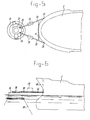
- Figure 4 is a side-view of a further embodiment and
- Figure 5 is the corresponding top-view.
- Figure 6 is a side-view of a further embodiment and
- Figure 7 is the thereto corresponding top-view.
- Figure 8 is a top-view of another embodiment.
- Figure 1 illustrates a fixed positioned
body 1, such as a quay or tower, and a theretomoored ship 2. Said ship is kept at a distance from thequay 1 by means of one or more arms 3, of which one end is at 4 pivotable around a horizontal axis, attached to thequay 1 and of which the other end 5 is pivotable attached to a connection means 6, which may have the form of a cable, a chain or rod, theupper end 7 of which connection means is pivotably attached to theship 2. Aweight 8 is positioned onto said arm or arms under which influence in the connection means 6 a tensile force is created from which reset force component is derived in case theship 2 is dislocated in relation to thequay 1. - In the embodiment of Figure 2 the
ship 2 is moored to a buoy, comprising acylindrical body 9, with two tightly thereto connectedarms ends ship 2. - Between the arms a connecting
element 18 is installed bearing a rotatable rim orturntable 19 carrying the anchor chains 20. Said anchor chains are forming the weight acting onto thearms - In the embodiment illustrated in Figure 4 and 5 a
normal buoy 21 is used fastened toanchor chains 22 and carrying aturntable 23.Arms ends ship 2. - Eventually a flexible distance element 31 can be installed between said arms.
- The
arms weights - In the embodiment of Figure 6 and 7 a
buoy 34 is used fastened by means ofanchor chains 35 and carrying aturntable 36 integrated to thearm 37, which is bifurcated in bothends arm 37 may be embodied as a hollow arm with aballast space 42 and if necessary anadditional weight 43 can be installed onto said arm. - The embodiment of Figure 8 illustrates a buoy comprising of two
buoyancy bodies element 46 installed inbetween together with theturntable 47 for the anchor chains 48. The ends of saidarms ship 2 through connection means 49, 50. Said arms compriseballast spaces
Claims (7)
Applications Claiming Priority (2)
| Application Number | Priority Date | Filing Date | Title |
|---|---|---|---|
| NL8202335 | 1982-06-09 | ||
| NL8202335A NL8202335A (en) | 1982-06-09 | 1982-06-09 | Apparatus for holding a buoyant body in place relative to another body. |
Publications (3)
| Publication Number | Publication Date |
|---|---|
| EP0096445A1 true EP0096445A1 (en) | 1983-12-21 |
| EP0096445B1 EP0096445B1 (en) | 1986-10-15 |
| EP0096445B2 EP0096445B2 (en) | 1990-11-28 |
Family
ID=19839853
Family Applications (1)
| Application Number | Title | Priority Date | Filing Date |
|---|---|---|---|
| EP83200790A Expired - Lifetime EP0096445B2 (en) | 1982-06-09 | 1983-06-01 | System for maintaining a buoyancy body in position in relation to another body |
Country Status (6)
| Country | Link |
|---|---|
| US (1) | US4568295A (en) |
| EP (1) | EP0096445B2 (en) |
| BR (1) | BR8303046A (en) |
| ES (1) | ES8403394A1 (en) |
| IN (2) | IN160693B (en) |
| NL (1) | NL8202335A (en) |
Families Citing this family (24)
| Publication number | Priority date | Publication date | Assignee | Title |
|---|---|---|---|---|
| NL8202335A (en) * | 1982-06-09 | 1982-08-02 | Single Buoy Moorings | Apparatus for holding a buoyant body in place relative to another body. |
| NL8202334A (en) * | 1982-06-09 | 1982-08-02 | Single Buoy Moorings | DEVICE FOR MAINTAINING A FLOATING BODY IN PLACE WITH RESPECT TO ANOTHER BODY. |
| EP0105976A1 (en) * | 1982-10-15 | 1984-04-25 | Bluewater Terminal Systems N.V. | A single point mooring tower structure with rigid arm |
| NL188841C (en) * | 1983-05-03 | 1992-10-16 | Single Buoy Moorings | Mooring device. |
| AU2761801A (en) | 2000-01-07 | 2001-07-24 | Fmc Corporation | Mooring systems with active force reacting systems and passive damping |
| US6688930B2 (en) | 2001-05-22 | 2004-02-10 | Fmc Technologies, Inc. | Hybrid buoyant riser/tension mooring system |
| EP1283159A1 (en) | 2001-08-06 | 2003-02-12 | Single Buoy Moorings Inc. | Hydrocarbon fluid transfer system |
| US6851994B2 (en) * | 2002-03-08 | 2005-02-08 | Fmc Technologies, Inc. | Disconnectable mooring system and LNG transfer system and method |
| EP1378506B1 (en) * | 2002-07-05 | 2006-07-26 | BASF Agro B.V., Arnhem (NL), Wädenswil-Branch | Process for the preparation of phenyl pyrazole compounds |
| WO2004014722A2 (en) * | 2002-08-06 | 2004-02-19 | Fmc Technologies, Inc. | Duplex yoke mooring-system |
| US7007623B2 (en) * | 2002-11-12 | 2006-03-07 | Fmc Technologies, Inc. | Retrieval and connection system for a disconnectable mooring yoke |
| US20050016432A1 (en) * | 2003-07-24 | 2005-01-27 | Clark James N. | Mooring buoy fending system |
| EP1809940A1 (en) * | 2004-11-08 | 2007-07-25 | Shell Internationale Researchmaatschappij B.V. | Liquefied natural gas floating storage regasification unit |
| AT502385B1 (en) * | 2005-09-19 | 2007-03-15 | Intellectual Capital And Asset | METHOD AND DEVICE FOR REDUCING THE SWIMMING OF SHIPS |
| US8279714B2 (en) * | 2008-12-05 | 2012-10-02 | Wood Hole Oceanographic Institution | Compliant ocean wave mitigation device and method to allow underwater sound detection with oceanographic buoy moorings |
| US9650110B1 (en) | 2015-10-27 | 2017-05-16 | Sofec, Inc. | Disconnectable tower yoke assembly and method of using same |
| SG11202111062RA (en) | 2019-04-05 | 2021-11-29 | Sofec Inc | Disconnectable tower yoke mooring system and methods for using same |
| SG11202111061QA (en) | 2019-04-05 | 2021-11-29 | Sofec Inc | Disconnectable tower yoke mooring system and methods for using same |
| WO2021034828A1 (en) | 2019-08-19 | 2021-02-25 | Sofec, Inc. | Mooring systems and processes for using same |
| EP4054929A1 (en) | 2019-11-08 | 2022-09-14 | SOFEC, Inc. | Surge damping system and processes for using same |
| CN114829244A (en) | 2019-11-08 | 2022-07-29 | 索菲克股份有限公司 | Mooring support structure, system for mooring a vessel and method of use thereof |
| US10794539B1 (en) | 2019-12-05 | 2020-10-06 | Sofec, Inc. | Systems and processes for recovering a vapor from a vessel |
| US11459067B2 (en) | 2019-12-05 | 2022-10-04 | Sofec, Inc. | Systems and processes for recovering a condensate from a conduit |
| US10899602B1 (en) | 2019-12-05 | 2021-01-26 | Sofec, Inc. | Submarine hose configuration for transferring a gas from a buoy |
Citations (4)
| Publication number | Priority date | Publication date | Assignee | Title |
|---|---|---|---|---|
| FR2290345A1 (en) * | 1974-11-05 | 1976-06-04 | Ihc Holland Nv | MOORING DEVICE, ESPECIALLY FOR PERFORMING PRODUCTION TESTS ON GAS OR OIL WELLS ON THE HIGH SEAS |
| FR2420475B1 (en) | 1978-03-24 | 1980-10-24 | Emh | |
| US4309955A (en) * | 1980-02-29 | 1982-01-12 | Amtel, Inc. | Riser-to-vessel-mooring-terminal |
| EP0096446A1 (en) | 1982-06-09 | 1983-12-21 | Single Buoy Moorings Inc. | System for maintaining a buoyant body in position in relation to another body |
Family Cites Families (6)
| Publication number | Priority date | Publication date | Assignee | Title |
|---|---|---|---|---|
| US3077614A (en) * | 1960-07-20 | 1963-02-19 | Robert L Lloyd | Buoy for mooring vessels |
| FI42406B (en) * | 1962-08-17 | 1970-03-31 | Bp Tanker Co Ltd | |
| NL6414787A (en) * | 1964-12-18 | 1966-06-20 | ||
| US3899990A (en) * | 1970-06-10 | 1975-08-19 | Emh | Systems for anchoring ships at sea |
| NL173254B (en) * | 1978-03-07 | 1983-08-01 | Single Buoy Moorings | DEVICE FOR MAINTAINING A FLOATING BODY WITH REGARD TO ANOTHER FLOATING BODY |
| NL8202335A (en) * | 1982-06-09 | 1982-08-02 | Single Buoy Moorings | Apparatus for holding a buoyant body in place relative to another body. |
-
1982
- 1982-06-09 NL NL8202335A patent/NL8202335A/en not_active Application Discontinuation
-
1983
- 1983-06-01 EP EP83200790A patent/EP0096445B2/en not_active Expired - Lifetime
- 1983-06-07 BR BR8303046A patent/BR8303046A/en not_active IP Right Cessation
- 1983-06-09 IN IN729/CAL/83A patent/IN160693B/en unknown
- 1983-06-09 US US06/502,732 patent/US4568295A/en not_active Expired - Lifetime
- 1983-06-09 IN IN730/CAL/83A patent/IN159039B/en unknown
- 1983-06-09 ES ES523132A patent/ES8403394A1/en not_active Expired
Patent Citations (4)
| Publication number | Priority date | Publication date | Assignee | Title |
|---|---|---|---|---|
| FR2290345A1 (en) * | 1974-11-05 | 1976-06-04 | Ihc Holland Nv | MOORING DEVICE, ESPECIALLY FOR PERFORMING PRODUCTION TESTS ON GAS OR OIL WELLS ON THE HIGH SEAS |
| FR2420475B1 (en) | 1978-03-24 | 1980-10-24 | Emh | |
| US4309955A (en) * | 1980-02-29 | 1982-01-12 | Amtel, Inc. | Riser-to-vessel-mooring-terminal |
| EP0096446A1 (en) | 1982-06-09 | 1983-12-21 | Single Buoy Moorings Inc. | System for maintaining a buoyant body in position in relation to another body |
Also Published As
| Publication number | Publication date |
|---|---|
| EP0096445B2 (en) | 1990-11-28 |
| ES523132A0 (en) | 1984-03-16 |
| IN159039B (en) | 1987-03-14 |
| ES8403394A1 (en) | 1984-03-16 |
| BR8303046A (en) | 1984-01-31 |
| NL8202335A (en) | 1982-08-02 |
| US4568295A (en) | 1986-02-04 |
| IN160693B (en) | 1987-08-01 |
| EP0096445B1 (en) | 1986-10-15 |
Similar Documents
| Publication | Publication Date | Title |
|---|---|---|
| EP0096445A1 (en) | System for maintaining a buoyancy body in position in relation to another body | |
| EP0096446B2 (en) | System for maintaining a buoyant body in position in relation to another body | |
| US4031582A (en) | Floating structure | |
| US5816183A (en) | Submerged CALM buoy | |
| US4279543A (en) | Device for conveying a medium from means provided in a fixed position on a bottom below the water surface to a buoy body | |
| CN1157312C (en) | Anchoring device for anchoring objects floating on water | |
| EP0188840A1 (en) | Mooring device | |
| EP0287173B1 (en) | Mooring device | |
| KR20210111782A (en) | Yoke plate assembly for mooring arrangement and mooring arrangement comprising the yoke plate assembly | |
| GB2123883A (en) | Improvements in and relating to ocean platforms | |
| US4567843A (en) | Mooring system | |
| EP0079404B2 (en) | A single point mooring buoy with rigid arm | |
| US4784079A (en) | Apparatus such as a working platform which by means of tension loaded tension member has been anchored and which has been provided with means for mooring a vessel | |
| EP0096119B1 (en) | A rigid arm single point mooring system for vessels | |
| US4309955A (en) | Riser-to-vessel-mooring-terminal | |
| GB2136375A (en) | Mooring system for tanker ships | |
| US4907996A (en) | Mooring system | |
| US4533332A (en) | Mooring system | |
| EP0182439A1 (en) | Fender or similar device for absorbing forces of impact | |
| GB1591945A (en) | Connecting arrangement for connecting a floating structure to an anchor | |
| EP0407662A1 (en) | Device for positioning of a buoy body | |
| US4836813A (en) | Mooring system | |
| EP0134596A1 (en) | Mooring buoy | |
| GB2139978A (en) | Mooring device | |
| EP0252544B1 (en) | Mooring device |
Legal Events
| Date | Code | Title | Description |
|---|---|---|---|
| PUAI | Public reference made under article 153(3) epc to a published international application that has entered the european phase |
Free format text: ORIGINAL CODE: 0009012 |
|
| AK | Designated contracting states |
Designated state(s): FR GB IT NL |
|
| 17P | Request for examination filed |
Effective date: 19840119 |
|
| GRAA | (expected) grant |
Free format text: ORIGINAL CODE: 0009210 |
|
| AK | Designated contracting states |
Kind code of ref document: B1 Designated state(s): FR GB IT NL |
|
| ITF | It: translation for a ep patent filed |
Owner name: STUDIO TORTA SOCIETA' SEMPLICE |
|
| ET | Fr: translation filed | ||
| PLBI | Opposition filed |
Free format text: ORIGINAL CODE: 0009260 |
|
| 26 | Opposition filed |
Opponent name: BLUEWATER TERMINAL SYSTEMS N.V. Effective date: 19870715 |
|
| NLR1 | Nl: opposition has been filed with the epo |
Opponent name: BLUEWATER TERMINAL SYSTEMS N.V. |
|
| PUAH | Patent maintained in amended form |
Free format text: ORIGINAL CODE: 0009272 |
|
| STAA | Information on the status of an ep patent application or granted ep patent |
Free format text: STATUS: PATENT MAINTAINED AS AMENDED |
|
| 27A | Patent maintained in amended form |
Effective date: 19901128 |
|
| AK | Designated contracting states |
Kind code of ref document: B2 Designated state(s): FR GB IT NL |
|
| NLR2 | Nl: decision of opposition | ||
| ITF | It: translation for a ep patent filed |
Owner name: STUDIO TORTA SOCIETA' SEMPLICE |
|
| ET3 | Fr: translation filed ** decision concerning opposition | ||
| NLR3 | Nl: receipt of modified translations in the netherlands language after an opposition procedure | ||
| ITTA | It: last paid annual fee | ||
| REG | Reference to a national code |
Ref country code: GB Ref legal event code: IF02 |
|
| PGFP | Annual fee paid to national office [announced via postgrant information from national office to epo] |
Ref country code: GB Payment date: 20020529 Year of fee payment: 20 |
|
| PGFP | Annual fee paid to national office [announced via postgrant information from national office to epo] |
Ref country code: FR Payment date: 20020610 Year of fee payment: 20 |
|
| PGFP | Annual fee paid to national office [announced via postgrant information from national office to epo] |
Ref country code: NL Payment date: 20020628 Year of fee payment: 20 |
|
| PG25 | Lapsed in a contracting state [announced via postgrant information from national office to epo] |
Ref country code: GB Free format text: LAPSE BECAUSE OF EXPIRATION OF PROTECTION Effective date: 20030531 |
|
| PG25 | Lapsed in a contracting state [announced via postgrant information from national office to epo] |
Ref country code: NL Free format text: LAPSE BECAUSE OF EXPIRATION OF PROTECTION Effective date: 20030601 |
|
| REG | Reference to a national code |
Ref country code: GB Ref legal event code: PE20 |
|
| NLV7 | Nl: ceased due to reaching the maximum lifetime of a patent |
Effective date: 20030601 |