EP0095960A1 - Einrichtung zum Speichern eines kohärenten Bildes in einem optischen Multimodalhohlraum - Google Patents
Einrichtung zum Speichern eines kohärenten Bildes in einem optischen Multimodalhohlraum Download PDFInfo
- Publication number
- EP0095960A1 EP0095960A1 EP83400987A EP83400987A EP0095960A1 EP 0095960 A1 EP0095960 A1 EP 0095960A1 EP 83400987 A EP83400987 A EP 83400987A EP 83400987 A EP83400987 A EP 83400987A EP 0095960 A1 EP0095960 A1 EP 0095960A1
- Authority
- EP
- European Patent Office
- Prior art keywords
- wave
- cavity
- medium
- signal wave
- signal
- Prior art date
- Legal status (The legal status is an assumption and is not a legal conclusion. Google has not performed a legal analysis and makes no representation as to the accuracy of the status listed.)
- Granted
Links
- 230000003287 optical effect Effects 0.000 title claims abstract description 33
- 230000001427 coherent effect Effects 0.000 title claims abstract description 24
- 239000000463 material Substances 0.000 claims description 13
- 230000002452 interceptive effect Effects 0.000 claims description 9
- JRPBQTZRNDNNOP-UHFFFAOYSA-N barium titanate Chemical compound [Ba+2].[Ba+2].[O-][Ti]([O-])([O-])[O-] JRPBQTZRNDNNOP-UHFFFAOYSA-N 0.000 claims description 6
- 229910002113 barium titanate Inorganic materials 0.000 claims description 6
- ORCSMBGZHYTXOV-UHFFFAOYSA-N bismuth;germanium;dodecahydrate Chemical compound O.O.O.O.O.O.O.O.O.O.O.O.[Ge].[Ge].[Ge].[Bi].[Bi].[Bi].[Bi] ORCSMBGZHYTXOV-UHFFFAOYSA-N 0.000 claims description 3
- JSILWGOAJSWOGY-UHFFFAOYSA-N bismuth;oxosilicon Chemical compound [Bi].[Si]=O JSILWGOAJSWOGY-UHFFFAOYSA-N 0.000 claims description 3
- UKDIAJWKFXFVFG-UHFFFAOYSA-N potassium;oxido(dioxo)niobium Chemical compound [K+].[O-][Nb](=O)=O UKDIAJWKFXFVFG-UHFFFAOYSA-N 0.000 claims description 3
- 238000003860 storage Methods 0.000 abstract description 10
- 238000012546 transfer Methods 0.000 abstract description 6
- 238000012545 processing Methods 0.000 abstract description 5
- 238000005086 pumping Methods 0.000 abstract description 5
- 230000003993 interaction Effects 0.000 abstract description 4
- 239000013078 crystal Substances 0.000 description 14
- 239000000835 fiber Substances 0.000 description 10
- 230000010363 phase shift Effects 0.000 description 9
- 230000003321 amplification Effects 0.000 description 8
- 238000003199 nucleic acid amplification method Methods 0.000 description 8
- 230000008878 coupling Effects 0.000 description 6
- 238000010168 coupling process Methods 0.000 description 6
- 238000005859 coupling reaction Methods 0.000 description 6
- 230000010355 oscillation Effects 0.000 description 6
- 238000005286 illumination Methods 0.000 description 5
- PEDCQBHIVMGVHV-UHFFFAOYSA-N Glycerine Chemical compound OCC(O)CO PEDCQBHIVMGVHV-UHFFFAOYSA-N 0.000 description 4
- 238000010521 absorption reaction Methods 0.000 description 3
- 230000009471 action Effects 0.000 description 3
- 230000007246 mechanism Effects 0.000 description 3
- 238000000034 method Methods 0.000 description 3
- 230000008569 process Effects 0.000 description 3
- XKRFYHLGVUSROY-UHFFFAOYSA-N Argon Chemical compound [Ar] XKRFYHLGVUSROY-UHFFFAOYSA-N 0.000 description 2
- 238000001228 spectrum Methods 0.000 description 2
- 108010010803 Gelatin Proteins 0.000 description 1
- BQCADISMDOOEFD-UHFFFAOYSA-N Silver Chemical compound [Ag] BQCADISMDOOEFD-UHFFFAOYSA-N 0.000 description 1
- XOTVYQNEABUPLI-UHFFFAOYSA-N [Si].[Bi]=O Chemical compound [Si].[Bi]=O XOTVYQNEABUPLI-UHFFFAOYSA-N 0.000 description 1
- 229910052786 argon Inorganic materials 0.000 description 1
- 230000005540 biological transmission Effects 0.000 description 1
- 230000008859 change Effects 0.000 description 1
- 230000001066 destructive effect Effects 0.000 description 1
- 238000011161 development Methods 0.000 description 1
- 238000010586 diagram Methods 0.000 description 1
- 238000009792 diffusion process Methods 0.000 description 1
- 238000009826 distribution Methods 0.000 description 1
- 229920000159 gelatin Polymers 0.000 description 1
- 239000008273 gelatin Substances 0.000 description 1
- 235000019322 gelatine Nutrition 0.000 description 1
- 235000011852 gelatine desserts Nutrition 0.000 description 1
- 238000004519 manufacturing process Methods 0.000 description 1
- 239000000203 mixture Substances 0.000 description 1
- 229920000642 polymer Polymers 0.000 description 1
- 230000001902 propagating effect Effects 0.000 description 1
- 230000002787 reinforcement Effects 0.000 description 1
- 238000011160 research Methods 0.000 description 1
- 230000004044 response Effects 0.000 description 1
- 229910052709 silver Inorganic materials 0.000 description 1
- 239000004332 silver Substances 0.000 description 1
Images


Classifications
-
- G—PHYSICS
- G03—PHOTOGRAPHY; CINEMATOGRAPHY; ANALOGOUS TECHNIQUES USING WAVES OTHER THAN OPTICAL WAVES; ELECTROGRAPHY; HOLOGRAPHY
- G03H—HOLOGRAPHIC PROCESSES OR APPARATUS
- G03H1/00—Holographic processes or apparatus using light, infrared or ultraviolet waves for obtaining holograms or for obtaining an image from them; Details peculiar thereto
-
- G—PHYSICS
- G02—OPTICS
- G02F—OPTICAL DEVICES OR ARRANGEMENTS FOR THE CONTROL OF LIGHT BY MODIFICATION OF THE OPTICAL PROPERTIES OF THE MEDIA OF THE ELEMENTS INVOLVED THEREIN; NON-LINEAR OPTICS; FREQUENCY-CHANGING OF LIGHT; OPTICAL LOGIC ELEMENTS; OPTICAL ANALOGUE/DIGITAL CONVERTERS
- G02F1/00—Devices or arrangements for the control of the intensity, colour, phase, polarisation or direction of light arriving from an independent light source, e.g. switching, gating or modulating; Non-linear optics
- G02F1/01—Devices or arrangements for the control of the intensity, colour, phase, polarisation or direction of light arriving from an independent light source, e.g. switching, gating or modulating; Non-linear optics for the control of the intensity, phase, polarisation or colour
- G02F1/03—Devices or arrangements for the control of the intensity, colour, phase, polarisation or direction of light arriving from an independent light source, e.g. switching, gating or modulating; Non-linear optics for the control of the intensity, phase, polarisation or colour based on ceramics or electro-optical crystals, e.g. exhibiting Pockels effect or Kerr effect
- G02F1/0338—Devices or arrangements for the control of the intensity, colour, phase, polarisation or direction of light arriving from an independent light source, e.g. switching, gating or modulating; Non-linear optics for the control of the intensity, phase, polarisation or colour based on ceramics or electro-optical crystals, e.g. exhibiting Pockels effect or Kerr effect structurally associated with a photoconductive layer or having photo-refractive properties
-
- G—PHYSICS
- G02—OPTICS
- G02F—OPTICAL DEVICES OR ARRANGEMENTS FOR THE CONTROL OF LIGHT BY MODIFICATION OF THE OPTICAL PROPERTIES OF THE MEDIA OF THE ELEMENTS INVOLVED THEREIN; NON-LINEAR OPTICS; FREQUENCY-CHANGING OF LIGHT; OPTICAL LOGIC ELEMENTS; OPTICAL ANALOGUE/DIGITAL CONVERTERS
- G02F1/00—Devices or arrangements for the control of the intensity, colour, phase, polarisation or direction of light arriving from an independent light source, e.g. switching, gating or modulating; Non-linear optics
- G02F1/01—Devices or arrangements for the control of the intensity, colour, phase, polarisation or direction of light arriving from an independent light source, e.g. switching, gating or modulating; Non-linear optics for the control of the intensity, phase, polarisation or colour
- G02F1/03—Devices or arrangements for the control of the intensity, colour, phase, polarisation or direction of light arriving from an independent light source, e.g. switching, gating or modulating; Non-linear optics for the control of the intensity, phase, polarisation or colour based on ceramics or electro-optical crystals, e.g. exhibiting Pockels effect or Kerr effect
- G02F1/05—Devices or arrangements for the control of the intensity, colour, phase, polarisation or direction of light arriving from an independent light source, e.g. switching, gating or modulating; Non-linear optics for the control of the intensity, phase, polarisation or colour based on ceramics or electro-optical crystals, e.g. exhibiting Pockels effect or Kerr effect with ferro-electric properties
- G02F1/0541—Devices or arrangements for the control of the intensity, colour, phase, polarisation or direction of light arriving from an independent light source, e.g. switching, gating or modulating; Non-linear optics for the control of the intensity, phase, polarisation or colour based on ceramics or electro-optical crystals, e.g. exhibiting Pockels effect or Kerr effect with ferro-electric properties using photorefractive effects
Definitions
- the invention relates to a device for storing a coherent image in a multimode optical cavity.
- optical information takes various forms and affects many fields of application: it can be the recording of two-dimensional or three-dimensional objects for backup purposes.
- Photography is the primary and still essential form of optical storage, but lasers have prompted the development of new processes applicable in particular to the audiovisual and computer fields.
- two applications seem to represent the possibilities offered by optical storage: holographic storage and storage of television images on "video disc”.
- the field of the invention is that of storage and subsequent processing, then made possible, of coherent images. But unlike the two applications previously named, this field is that of the dynamic recording of coherent images.
- the device of the invention comprises a multimode optical cavity, in which a stable oscillation of the coherent image is maintained.
- the subject of the present invention is a device for storing a coherent image in a multimode optical cavity, comprising at least one coherent source which generates at least a first signal wave and at least a second reference wave, optical guide means making it possible to form a closed loop in which each signal wave circulates, an interactive amplifying medium being arranged on the path of each signal wave and on that of each reference wave, each signal wave interfering with a reference wave in this medium to create a network of diffraction, each signal wave receiving energy from this reference wave, characterized in that these guide means form a multimode optical cavity, this interactive amplifying medium being disposed in the Fourier plane of this cavity, a semi-transparent plate being arranged on the path of each signal wave to extract part of the energy from the multimode optical cavity.
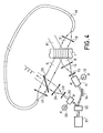
- FIG. 4 illustrates a device of the known art which uses an amplification of this type: this device allowing the amplification of a wave of incident radiant energy by transferring the energy of a pumping beam towards the signal. It thus ensures the circulation of a pulse of radiant energy in a fiber while maintaining the level of the signal whatever the number of revolutions traveled.
- the device of the invention uses wave coupling phenomena when reading phase networks.
- a phase grating with high diffraction efficiency recorded permanently on a photosensitive support consisting of thick diffracting phase structures, photoinduced by index variation in electro-optical crystals, photo-polymers or bleached silver materials.
- a given grating of step A will significantly diffract a reading beam of wavelength ⁇ , if it arrives on the medium with the angle 0, linked to X and A by this Bragg relation.
- the pitch A resulting from the interference of R and S is strictly identical to that of the phase network, and it is, for example, these same R and S beams which were used for the manufacture of the network of strata which was previously registered .
- the object wave S has interfered with a reference wave R with a plane wavefront.
- a network of interference fringes thus created generated in the crystal, a network of index strata.
- This network of strata diffracts part of the energy of the reference wave R into a diffracted wave S 'whose wave front is isomorphic from the object wave front.
- the energy transfer is therefore optimum when the following conditions are satisfied simultaneously:
- the incident R wave is diffracted by the three-dimensional phase grating.
- the wave S 'thus generated is, for example, in phase delay of ⁇ / 2 with respect to the reading wave R.
- phase shift of ⁇ / 2 between the interference network 31 of the two beams and the phase network 30, as shown in FIG. 2.
- the wave R ' which is generated by diffraction of the wave S, would be in phase advance by ⁇ / 2 with respect to this same S wave.
- FIG. 4 A device of the known art based on the previously described wave coupling phenomena is shown in FIG. 4.
- the light intensity network of the interference of the two beams R and S is phase shifted by tr / 2 with respect to the phase network which has the consequence of obtaining a wave diffracted from the R wave on the phase grating superimposed on the transmitted S wave: everything happens as if the transmitted wave S 'is enriched with a fraction of the energy of the reference wave.
- the beam S ′ originating from the network is coupled to the propagation medium which may for example be a waveguide or a single-mode fiber by means of conventional optical components.
- the medium 1 is coupled to the fiber 16 by means of the converging lenses 15 and 17.
- the two beams S and R come from the same laser 21 after crossing a beam splitter 22.
- the beam R passes through a phase modulator 11 then a beam expander composed of two lenses 13 and 14, after having been previously reflected by a mirror 34.
- the beam S consists of a pulse radiant energy which is initially entered by an amplitude modulator 33 controlled by a generator 32. This pulse after crossing a beam expander (23, 24) is entered into the loop via a blade separator 25. This same separator blade also makes it possible to take out the impulse which circulates in the loop formed by the fiber 16 coupled to the medium 1. One can moreover remove this blade once the process has started.
- the outgoing signal from this fiber 16 is reinjected at the input of the network where it interferes in a coherent manner with the R wave coming from the laser 21.
- This modulator being attacked by a voltage V, the losses by optical absorption and by coupling of the signal wave S are adjusted to 3 dB.
- the losses due to the external coupling of the beam S via a separating plate 18 are approximately 1 dB, and the losses due to the coupling between the fiber 16 and the medium 1 and the losses in this fiber 16 are about 2 dB.
- the gain obtained by energy transfer from the pumping wave R to the signal wave S compensates for the losses and the level of the signal pulse remains the same regardless of the number of passages in the propagation medium. .
- the requirements for the coherence length of the single-mode source can be reduced if the transit time T of the pulse in the fiber is a multiple of -; 1 being the length of the laser cavity. Indeed - is the time interval between two maxima of coherence for a laser cavity. There is then good consistency in the operation of the loop formed by the coil 16 and the medium 1 with respect to the operation of the laser cavity.
- the device of the known art therefore ensures the circulation of a single optical pulse in a fiber, or single-mode guide by keeping the signal level constant whatever the number of revolutions traveled.
- the object wave is no longer a simple pulse but it can have a front of any wave.
- the amplifying medium consists of a photorefractive material operating by variation of photoinduced index.
- the addition of a feedback loop consisting of mirrors and lenses makes it possible to produce a multimode optical cavity and to maintain a stable oscillation of the image in the cavity.
- the first type of operation can be envisaged with materials of the silicon Bismuth oxide type, Bismuth Germanium oxide, and the second type of operation with materials of the potassium niobate type, or barium titanate.
- the device of the invention makes it possible to use this optical parametric amplifier where all the beams are at the same frequency to produce a multimode oscillator compatible with an image signal.
- the light oscillator comprises a light amplifying medium, and a set of mirrors constituting what is called the "resonator” or , by analogy with microwave oscillators, the "cavity" of the laser.
- An oscillation wave therefore propagates inside this cavity.
- a laser cavity consisting of the following elements: two mirrors M 1 and M 2 between which the object wave circulates, and an amplifying medium 1 located on the path of this object wave.
- Two lenses L 1 and L 2 make it possible to define the path of this object wave in the cavity.
- the mirror M 1 is partially reflecting, for example semi-transparent, and allows the introduction of the object wave into the cavity, as shown in FIG. 5; the input signal can then be suppressed as illustrated in FIG. 6.
- the input signal consists of a slide or any other electro-optical transducer used for the composition of the image in real time. It can also be any three-dimensional object illuminated by a beam of coherent light whose image is brought back in a plane.
- the amplifying medium 1 is placed in the vicinity of the Fourier plane of the lens L 1 , which allows processing of the spectrum of the image.
- the mirror M 1 ensures both the introduction of the signal from the incident image and the reflection of the amplified wave rotating in the cavity.
- Another semi-transparent plate M 3 makes it possible to extract a fraction of the energy contained in the cavity, the lens L 3 allows the projection of the image in a plane P.
- the oscillation condition of this cavity is ensured if the gain of the amplifying medium is greater than the losses of the cavity due in particular to the mirrors M 1 , M 2 and to the reflections on the optical components.
- the number N of points of the image capable of being processed in parallel in this multimode cavity is a direct function of the size of the amplifier crystal which results in a limitation of the spectrum of spatial frequencies.
- This value corresponds to the number of independent modes likely to oscillate in the cavity.
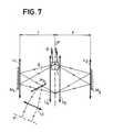
- FIG. 7 An alternative to the optical configuration of FIG. 5 is given by way of example in FIG. 7. This more compact structure than the previous one also performs the function of a multimode optical cavity.
- the distance separating the mirrors is four times the focal distance f of the lenses L 1 and L 2 assumed to be identical.
- the introduction of the lenses L 4 and L 5 makes it possible to consider a cavity whose distance between the two mirrors is approximately twice this focal distance, these mirrors being assumed to be glued to the lenses L 1 and L 2 .
- a stable oscillation can be maintained in the absence of the initial incident image signal if the following two conditions are met.
- the optical path l opt seen by all the modes of the cavity is the same and is worth a multiple of the wavelength: in an equivalent way the phase shift induced by the course of the cavity is worth 2 K ⁇ .
- the device of the invention responds to the Fabry-Perrot formalism, we add waves which have traversed paths of length l opt , 21 opt '31 opt ... and which meet the phase condition stated above.
- an electro-optical shutter 2 for example makes it possible to cut the oscillating signal beam in the cavity.
- the photorefractive crystal is then uniformly illuminated by the reference wave (or pump wave) which relaxes the variation in photoinduced index.
- an amplitude and phase filter 3 can be placed in the common Fourier plane of the lenses L 1 - L 2 in order to modify the content in spatial frequencies of the image.
- Photorefractive materials constitute an interesting solution for the coherent amplification of images by energy transfer from a pump wave.
- the crystals used are: Potassium Niobate (K Nb 0 3 ), Barium Titanate (Ba Ti 0 3 ), Bismuth-Silicon oxide (Bi 12 Si O 20 ), Bismuth-Germanium oxide (Bi 12 Ge 0 20 ).
- K Nb 0 3 Potassium Niobate
- Ba Ti 0 3 Barium Titanate
- Bismuth-Silicon oxide Bi 12 Si O 20
- Bismuth-Germanium oxide Bi 12 Ge 0 20
- the incidence of the incident wave on the crystal then corresponds to the highest electro-optical coefficient; this incidence is of the order of 45 ° for example.
- the recording energies required in the visible range are typically of the order of 100 p J cm -2 for Bismuth-Silicon oxide to 100 m J cm -2 for Barium Titanate, therefore compatible with the levels of power available from an Argon laser.
- the wave which propagates in the cavity must therefore respond to phase conditions at the entrance to the cavity; the network registered in the amplifying medium therefore stabilizes, with each pass the registered network is therefore superimposed on the previously registered network.
- the interference system inscribed in this medium can, depending on the dynamics of the material considered, include n different networks, but then the maximum index variation is divided by n, there is less gain for each network.
- n can be equal to 10. So for example we can consider the instantaneous illumination of the crystal by three signal waves at three different wavelengths ⁇ 1 , ⁇ 2 , ⁇ 3 , which therefore entails, if we consider three reference waves of the same wavelengths: ⁇ 1 , ⁇ 2 , ⁇ 3 , the registration of three networks at the same time.
- the device of the invention therefore allows the storage of a coherent three-color image.
- the mirrors used in FIGS. 5 and 6 are plane mirrors which have their reflecting surfaces parallel to each other but this is not necessary, they can have reflecting surfaces forming an angle between them, or they can be spherical mirrors.
- the incidence of the object wave entering the cavity must be such that, after passing through the lens L I , it reaches the amplifying medium 1.
- these optical guidance means: lenses, mirrors must allow the optical path to close on itself to thus form a closed loop.
- the device of the invention allows the storage and processing of a coherent optical image.
Applications Claiming Priority (2)
| Application Number | Priority Date | Filing Date | Title |
|---|---|---|---|
| FR8209448 | 1982-05-28 | ||
| FR8209448A FR2527799B1 (fr) | 1982-05-28 | 1982-05-28 | Dispositif de mise en memoire d'une image coherente dans une cavite optique multimode |
Publications (2)
| Publication Number | Publication Date |
|---|---|
| EP0095960A1 true EP0095960A1 (de) | 1983-12-07 |
| EP0095960B1 EP0095960B1 (de) | 1985-09-18 |
Family
ID=9274481
Family Applications (1)
| Application Number | Title | Priority Date | Filing Date |
|---|---|---|---|
| EP83400987A Expired EP0095960B1 (de) | 1982-05-28 | 1983-05-17 | Einrichtung zum Speichern eines kohärenten Bildes in einem optischen Multimodalhohlraum |
Country Status (5)
| Country | Link |
|---|---|
| US (1) | US4586779A (de) |
| EP (1) | EP0095960B1 (de) |
| JP (1) | JPS58215679A (de) |
| DE (1) | DE3360833D1 (de) |
| FR (1) | FR2527799B1 (de) |
Cited By (3)
| Publication number | Priority date | Publication date | Assignee | Title |
|---|---|---|---|---|
| EP0138668A2 (de) * | 1983-09-23 | 1985-04-24 | Thomson-Csf | Einrichtung zur Aufnahme eines kohärenten Bildes in einem multimoden-optischen Hohlraum |
| EP0206681A2 (de) * | 1985-06-14 | 1986-12-30 | The Board Of Trustees Of The Leland Stanford Junior University | Optisches Verfahren zur Bildung eines Hologramms |
| CN1060578C (zh) * | 1996-03-06 | 2001-01-10 | 北京工业大学 | 盘式三维全息存储的方法及其光学系统 |
Families Citing this family (14)
| Publication number | Priority date | Publication date | Assignee | Title |
|---|---|---|---|---|
| US4761059A (en) * | 1986-07-28 | 1988-08-02 | Rockwell International Corporation | External beam combining of multiple lasers |
| US4784473A (en) * | 1987-03-02 | 1988-11-15 | United States Of America As Represented By The Secretary Of The Navy | Ferroelectric optical switching |
| US4849940A (en) * | 1987-12-10 | 1989-07-18 | The Washington Technology Center | Optical neural net memory |
| US5019512A (en) * | 1989-03-17 | 1991-05-28 | Baxter International Inc. | Spin filter for removing substantially cell-free culture medium from suspension cell culture system |
| FR2647229B1 (fr) * | 1989-05-16 | 1991-07-05 | Thomson Csf | Dispositif d'amplification d'onde optique a faible bruit |
| FR2681988A1 (fr) * | 1991-09-27 | 1993-04-02 | Thomson Csf | Laser de puissance a deflexion. |
| FR2696014B1 (fr) * | 1992-09-18 | 1994-11-04 | Thomson Csf | Miroir à conjugaison de phase. |
| FR2755516B1 (fr) | 1996-11-05 | 1999-01-22 | Thomson Csf | Dispositif compact d'illumination |
| FR2819061B1 (fr) * | 2000-12-28 | 2003-04-11 | Thomson Csf | Dispositif de controle de polarisation dans une liaison optique |
| CN101351843A (zh) * | 2005-12-27 | 2009-01-21 | 皇家飞利浦电子股份有限公司 | 用于读取全息存储介质上的数据的系统 |
| EP3745605B1 (de) | 2016-03-22 | 2022-08-24 | Lyteloop Technologies, Llc | Daten in bewegungsspeicherungssystem und -verfahren |
| US11361794B2 (en) | 2018-08-02 | 2022-06-14 | Lyteloop Technologies, Llc | Apparatus and method for storing wave signals in a cavity |
| MX2020009303A (es) | 2018-08-10 | 2022-03-22 | Lyteloop Tech Llc | Sistema y procedimiento para extender la longitud de trayectoria de una señal de onda usando multiplexación en ángulo. |
| WO2020096912A1 (en) | 2018-11-05 | 2020-05-14 | Lyteloop Technologies, Llc | Systems and methods for building, operating and controlling multiple amplifiers, regenerators and transceivers using shared common components |
Citations (3)
| Publication number | Priority date | Publication date | Assignee | Title |
|---|---|---|---|---|
| US3466110A (en) * | 1966-03-24 | 1969-09-09 | Ibm | Laser projector for phase modulating objects |
| US3632182A (en) * | 1970-03-05 | 1972-01-04 | Ibm | Method and apparatus for interference pattern recording |
| EP0061360A1 (de) * | 1981-02-27 | 1982-09-29 | Thomson-Csf | Optische Vorrichtung zum Unterhalten eines in einem Monomode-Wellenleiter zirkulierenden Strahlungsenergieimpulses; Gyrometer und Hydrophon mit einer solchen Vorrichtung |
Family Cites Families (1)
| Publication number | Priority date | Publication date | Assignee | Title |
|---|---|---|---|---|
| FR2395534A1 (fr) * | 1977-06-24 | 1979-01-19 | Thomson Csf | Dispositif d'imagerie acousto-optique a detection holographique coherente en temps reel |
-
1982
- 1982-05-28 FR FR8209448A patent/FR2527799B1/fr not_active Expired
-
1983
- 1983-05-17 EP EP83400987A patent/EP0095960B1/de not_active Expired
- 1983-05-17 DE DE8383400987T patent/DE3360833D1/de not_active Expired
- 1983-05-24 US US06/497,682 patent/US4586779A/en not_active Expired - Fee Related
- 1983-05-28 JP JP58093395A patent/JPS58215679A/ja active Pending
Patent Citations (3)
| Publication number | Priority date | Publication date | Assignee | Title |
|---|---|---|---|---|
| US3466110A (en) * | 1966-03-24 | 1969-09-09 | Ibm | Laser projector for phase modulating objects |
| US3632182A (en) * | 1970-03-05 | 1972-01-04 | Ibm | Method and apparatus for interference pattern recording |
| EP0061360A1 (de) * | 1981-02-27 | 1982-09-29 | Thomson-Csf | Optische Vorrichtung zum Unterhalten eines in einem Monomode-Wellenleiter zirkulierenden Strahlungsenergieimpulses; Gyrometer und Hydrophon mit einer solchen Vorrichtung |
Non-Patent Citations (5)
| Title |
|---|
| APPLIED PHYSICS, vol. 8, 1975, pages 51-58, Springer-Verlag, Heidelberg, DE. * |
| IBM TECHNICAL DISCLOSURE BULLETIN, vol. 23, no. 2, juillet 1980, pages 831-832, New York, USA * |
| OPTICAL ENGINEERING, vol. 21, no. 2, mars-avril 1982, pages 224-230, Bellingham, Washington, USA * |
| OPTICS COMMUNICATIONS, vol. 38, no. 4, 15 août 1981, pages 249-254, North-Holland Publishing Company, Amsterdam, NL. * |
| OPTICS LETTERS, vol. 6, no. 12, decembre 1981, pages 622-624, Optical Society of America, New York, USA * |
Cited By (5)
| Publication number | Priority date | Publication date | Assignee | Title |
|---|---|---|---|---|
| EP0138668A2 (de) * | 1983-09-23 | 1985-04-24 | Thomson-Csf | Einrichtung zur Aufnahme eines kohärenten Bildes in einem multimoden-optischen Hohlraum |
| EP0138668A3 (en) * | 1983-09-23 | 1986-01-22 | Thomson-Csf | Device for recording a coherent image in a multimodal optical cavity |
| EP0206681A2 (de) * | 1985-06-14 | 1986-12-30 | The Board Of Trustees Of The Leland Stanford Junior University | Optisches Verfahren zur Bildung eines Hologramms |
| EP0206681A3 (en) * | 1985-06-14 | 1988-03-23 | The Board Of Trustees Of The Leland Stanford Junior University | Optical system for forming a hologram optical system for forming a hologram |
| CN1060578C (zh) * | 1996-03-06 | 2001-01-10 | 北京工业大学 | 盘式三维全息存储的方法及其光学系统 |
Also Published As
| Publication number | Publication date |
|---|---|
| DE3360833D1 (en) | 1985-10-24 |
| EP0095960B1 (de) | 1985-09-18 |
| FR2527799B1 (fr) | 1986-05-23 |
| JPS58215679A (ja) | 1983-12-15 |
| FR2527799A1 (fr) | 1983-12-02 |
| US4586779A (en) | 1986-05-06 |
Similar Documents
| Publication | Publication Date | Title |
|---|---|---|
| EP0095960B1 (de) | Einrichtung zum Speichern eines kohärenten Bildes in einem optischen Multimodalhohlraum | |
| EP0138668B1 (de) | Einrichtung zur Aufnahme eines kohärenten Bildes in einem multimoden-optischen Hohlraum | |
| US6673497B2 (en) | High efficiency volume diffractive elements in photo-thermo-refractive glass | |
| EP0061360B1 (de) | Optische Vorrichtung zum Unterhalten eines in einem Monomode-Wellenleiter zirkulierenden Strahlungsenergieimpulses; Gyrometer und Hydrophon mit einer solchen Vorrichtung | |
| EP1030418A1 (de) | Optischer Reflektor und dessen Benutzung in einem Laser mit externem Resonator | |
| EP0557162A1 (de) | Holographisches Strahlenschutzfilter, besonders für Laser | |
| EP0007268B1 (de) | Optische Strahlungsquelle, die ein mit einer gleichmässigen Winkelöffnung divergentes Strahlenbündel liefert | |
| EP0187058B1 (de) | Monomodenlichtquelle und abstimmbarer optischer Verstärker für Nahinfrarot | |
| EP0053052B1 (de) | Interferometrische Einrichtung zur Echtzeit-Sichtbarmachung der Verformungen von schwingenden Gegenständen | |
| EP0061372B1 (de) | Optische Einrichtung zur Echtzeit-Verstärkung der Strahlungsenergie eines Bündels | |
| EP0084996A2 (de) | Kinematographie-Einrichtung, mit Anwendung der Holographie | |
| EP0063977A1 (de) | Optische Interferometereinrichtung mit Phasenkonjugierungsspiegel, insbesondere für Laser-Gyrometer | |
| EP0708509B1 (de) | Vorrichtung zur Emission von Strahlung einer einzelnen Wellenlänge | |
| EP0141739B1 (de) | Interferometrische Anordnung zum Messen einer Winkeldrehgeschwindigkeit | |
| EP3657224B1 (de) | Feste oder einstellbare optische verzögerungsleitungsvorrichtung | |
| FR2742884A1 (fr) | Rejecteur spectral grand champ angulaire et procede de fabrication | |
| US6621633B2 (en) | System and method for increasing the diffraction efficiency of holograms | |
| FR2492541A1 (fr) | Concentrateur de rayonnement solaire et son procede de fabrication | |
| Eichler et al. | Mirrors | |
| Miler et al. | Diffraction components for integrated optics | |
| US7899292B2 (en) | Thermal nonlinearity cell for guiding electromagnetic energy through a nonlinear medium | |
| CA2312608C (fr) | Reflecteur optique et source laser a cavite externe incorporant un tel reflecteur | |
| Ludman et al. | Holographic Nonspatial Filtering for Laser Beams | |
| US20030035160A1 (en) | System and method for increasing the diffraction efficiency of holograms | |
| Morozov et al. | Diffraction components for integrated optics |
Legal Events
| Date | Code | Title | Description |
|---|---|---|---|
| PUAI | Public reference made under article 153(3) epc to a published international application that has entered the european phase |
Free format text: ORIGINAL CODE: 0009012 |
|
| AK | Designated contracting states |
Designated state(s): CH DE GB IT LI NL SE |
|
| 17P | Request for examination filed |
Effective date: 19831227 |
|
| ITF | It: translation for a ep patent filed |
Owner name: JACOBACCI & PERANI S.P.A. |
|
| GRAA | (expected) grant |
Free format text: ORIGINAL CODE: 0009210 |
|
| AK | Designated contracting states |
Designated state(s): CH DE GB IT LI NL SE |
|
| REF | Corresponds to: |
Ref document number: 3360833 Country of ref document: DE Date of ref document: 19851024 |
|
| PG25 | Lapsed in a contracting state [announced via postgrant information from national office to epo] |
Ref country code: LI Effective date: 19860531 Ref country code: CH Effective date: 19860531 |
|
| PLBE | No opposition filed within time limit |
Free format text: ORIGINAL CODE: 0009261 |
|
| STAA | Information on the status of an ep patent application or granted ep patent |
Free format text: STATUS: NO OPPOSITION FILED WITHIN TIME LIMIT |
|
| 26N | No opposition filed | ||
| REG | Reference to a national code |
Ref country code: CH Ref legal event code: PL |
|
| PGFP | Annual fee paid to national office [announced via postgrant information from national office to epo] |
Ref country code: NL Payment date: 19870531 Year of fee payment: 5 |
|
| REG | Reference to a national code |
Ref country code: GB Ref legal event code: 746 |
|
| PG25 | Lapsed in a contracting state [announced via postgrant information from national office to epo] |
Ref country code: NL Effective date: 19881201 |
|
| NLV4 | Nl: lapsed or anulled due to non-payment of the annual fee | ||
| PGFP | Annual fee paid to national office [announced via postgrant information from national office to epo] |
Ref country code: DE Payment date: 19890424 Year of fee payment: 7 |
|
| PGFP | Annual fee paid to national office [announced via postgrant information from national office to epo] |
Ref country code: GB Payment date: 19890430 Year of fee payment: 7 |
|
| PG25 | Lapsed in a contracting state [announced via postgrant information from national office to epo] |
Ref country code: SE Effective date: 19890518 |
|
| PG25 | Lapsed in a contracting state [announced via postgrant information from national office to epo] |
Ref country code: GB Effective date: 19900517 |
|
| GBPC | Gb: european patent ceased through non-payment of renewal fee | ||
| PG25 | Lapsed in a contracting state [announced via postgrant information from national office to epo] |
Ref country code: DE Effective date: 19910201 |
|
| EUG | Se: european patent has lapsed |
Ref document number: 83400987.0 Effective date: 19900412 |