EP0095912B1 - Blade holding device - Google Patents
Blade holding device Download PDFInfo
- Publication number
- EP0095912B1 EP0095912B1 EP83303078A EP83303078A EP0095912B1 EP 0095912 B1 EP0095912 B1 EP 0095912B1 EP 83303078 A EP83303078 A EP 83303078A EP 83303078 A EP83303078 A EP 83303078A EP 0095912 B1 EP0095912 B1 EP 0095912B1
- Authority
- EP
- European Patent Office
- Prior art keywords
- blade
- recess
- wedge
- members
- holding device
- Prior art date
- Legal status (The legal status is an assumption and is not a legal conclusion. Google has not performed a legal analysis and makes no representation as to the accuracy of the status listed.)
- Expired
Links
Images

Classifications
-
- B—PERFORMING OPERATIONS; TRANSPORTING
- B26—HAND CUTTING TOOLS; CUTTING; SEVERING
- B26D—CUTTING; DETAILS COMMON TO MACHINES FOR PERFORATING, PUNCHING, CUTTING-OUT, STAMPING-OUT OR SEVERING
- B26D1/00—Cutting through work characterised by the nature or movement of the cutting member or particular materials not otherwise provided for; Apparatus or machines therefor; Cutting members therefor
- B26D1/56—Cutting through work characterised by the nature or movement of the cutting member or particular materials not otherwise provided for; Apparatus or machines therefor; Cutting members therefor involving a cutting member which travels with the work otherwise than in the direction of the cut, i.e. flying cutter
- B26D1/62—Cutting through work characterised by the nature or movement of the cutting member or particular materials not otherwise provided for; Apparatus or machines therefor; Cutting members therefor involving a cutting member which travels with the work otherwise than in the direction of the cut, i.e. flying cutter and is rotating about an axis parallel to the line of cut, e.g. mounted on a rotary cylinder
- B26D1/626—Cutting through work characterised by the nature or movement of the cutting member or particular materials not otherwise provided for; Apparatus or machines therefor; Cutting members therefor involving a cutting member which travels with the work otherwise than in the direction of the cut, i.e. flying cutter and is rotating about an axis parallel to the line of cut, e.g. mounted on a rotary cylinder for thin material, e.g. for sheets, strips or the like
-
- B—PERFORMING OPERATIONS; TRANSPORTING
- B26—HAND CUTTING TOOLS; CUTTING; SEVERING
- B26D—CUTTING; DETAILS COMMON TO MACHINES FOR PERFORATING, PUNCHING, CUTTING-OUT, STAMPING-OUT OR SEVERING
- B26D7/00—Details of apparatus for cutting, cutting-out, stamping-out, punching, perforating, or severing by means other than cutting
- B26D7/26—Means for mounting or adjusting the cutting member; Means for adjusting the stroke of the cutting member
- B26D7/2614—Means for mounting the cutting member
-
- B—PERFORMING OPERATIONS; TRANSPORTING
- B41—PRINTING; LINING MACHINES; TYPEWRITERS; STAMPS
- B41F—PRINTING MACHINES OR PRESSES
- B41F13/00—Common details of rotary presses or machines
- B41F13/54—Auxiliary folding, cutting, collecting or depositing of sheets or webs
- B41F13/56—Folding or cutting
- B41F13/60—Folding or cutting crosswise
Definitions
- the present invention relates to a device for mounting and accurately seating a perforating or cutoff blade along a cylinder such as might be used for partially or completely severing a web at a plurality of locations along its length.
- Such devices are particularly useful in machines for continuous printing or collating of paper webs.
- the blade be capable of removal, replacement and/or repositioning along the rotating blade cylinder. From time to time during the operation of the machine, it is necessary to remove the blade from the cylinder, for instance, when it may be desired to print a web without perforating or severing the same, or when replacement of the blade is necessary due to dulling or breakage of the blade.
- a second requirement for such blade mounting arrangements is that the cutting edge of a perforating blade be capable of accurate seating against an anvil surface. Otherwise, an uneven perforation will result, with some sections of the perforation being too deep, or some sections being too shallow, or both. This produces variation in the tear strength along the perforation, with resultant high probability of jamming in subsequent printers or bursters.
- a backup or anvil cylinder may be included for providing a hardened anvil surface, or insert, or in some cases a die, to cooperate with the sharpened edge of the properly seated blade in perforating the passing web as the web moves between the rotating blade cylinder and anvil or backup cylinder.
- the blade is mounted to the rotating cylinder by clamping the blade into a recess or slot cut generally lengthwise into the cylinder periphery.
- the recess is rectangular in cross section, and the blade may be clamped against one of the side faces of the recess, or against an intermediate supporting bar.
- Several techniques are available, however, for providing proper seating of the cutting edge of the blade against the anvil surface.
- a perforating blade when manufactured, it includes some variation in height from its base to its cutting edge, as well as a tendency to bow in a lateral direction.
- One method for seating the blade is to use a blade which has been manufactured to very close tolerances with respect to both height and bow.
- the cylinder is provided with a recess that has been machined also to very close tolerances with respect to a uniform and specific depth.
- Seating of the blade is relatively simple, since the blade is loaded into the recess, with the base of the blade bottomed along the base of the recess, and is then clamped tightly in place.
- a second technique in which a blade having very loose height and bow tolerance may be used.
- the blade is inserted into the recess, but is not bottomed against the base of the recess, and is secured somewhat loosely along its length.
- the blade is then seated against the anvil surface, through a procedure known as "crash in”.
- This procedure consists of rotating the blade cylinder and anvil cylinder, with or without a web passing therebetween at inching speed through one revolution.
- the cutting edge of the blade is free to move under the seating force sufficiently into the recess, at whatever locations are necessary to obtain a uniform seating of the cutting edge against the anvil. While secured somewhat loosely, the blade must be nonetheless held tight enough to hold its seated position.
- the apparatus is then stopped and the blade is securely clamped along its entire length to prevent slip within the recess when the apparatus is operated at higher speeds.
- a third technique possessing some of the advantages and disadvantages of both techniques, utilizes a blade having close tolerance with respect to height only. While the blade is bottomed against the recess base, crash-in is required to remove vertical bow from the blade.
- a number of various devices for accurately securing a blade within a recess, suitable for holding the blade both for crash-in and for clamping are known.
- the blade may be placed against a side wall of the recess, and a bar inserted into the recess adjacent the blade.
- a plurality of bolt members are threaded into holes in the bar, extending from the side of the bar to the recess side wall opposite the blade.
- the bolt members are driven in a direction outwardly from the bar against the recess wall.
- Driving of the bolt members forces the bar tightly against the blade, thereby clamping it in place.
- the bolt members may be partially tightened, allowing the blade limited movement for seating against the anvil surface during crash-in, and then the bolt members may be completely tightened for clamping.
- a blade holding device in which a wedge bar is provided for clamping the blade into the cylinder recess.
- the blade is placed against a side wall of the recess, and the wedge bar is provided with a vertical taper, i.e., in a radial direction with respect to the cylinder.
- a non-rectangular cross-sectional recess may be provided, or an intermediate member placed between the blade and the wedge bar and having a taper opposite the wedge bar may be provided, along with a plurality of bolts extending through the wedge bar and into the cylinder at the bottom of the recess.
- the wedge bar By driving the bolts, the wedge bar is forced into the recess in a direction toward the axis of the cylinder, thereby securely clamping the blade into the recess.
- Preloading springs may be provided to act on the wedge bar with a force sufficient to retain the blade during crash-in while allowing limited movement of the blade within the recess for seating. Following seating, the bolts are tightened to firmly secure the blade.
- the Schriber et al device By providing the preloading springs for supplying sufficient clamping force for seating of the blade, the Schriber et al device eliminates the need for the operator to manipulate the bolts during the crash in process. Additionally, by providing bolts that are driven radially with respect to the cylinder, rather than disposed within the-recess, access to the bolts is facilitated. Nonetheless, the Schriber et al device utilizes a plurality of bolts to provide a relatively uniform clamping force on the blade. Moreover, since the bolts are disposed along the entire length of the wedge bar, the operator must reach along the full length of the cylinder during the clamping process. Thus, even with the Schriber et al blade holding device, the clamping process is both time-consuming and awkward to perform.
- Each bolt extends into a threaded bore in an end of one of the wedge bars, such that by rotating the bolts, each bar may be moved in either direction along the cylinder recess.
- the bolts are rotated such that the wedge bars are driven into the recess so as to wedge the blade into place.
- Notches or other indicia are provided along the upper surface of one of the wedge bars and the cylinder surface, so that the relative movement of the bar in relation to the cylinder for aligning the blade may be easily determined.
- the Richards et al device reduces the number of bolts which must be manipulated during the clamping process in comparison with the devices described above. It is indicated in the patent, however, that the primary purpose of the device is to enable the angle of the blade with respect to the direction of travel of the web to be somewhat adjustable, although the device seems better suited for adjusting the distance from the blade along the cylinder periphery to a next following blade. In either case, while such a feature may be desirable in compensating for an improperly machined cylinder and/or associated gears, it requires the operator of the device during the clamping process to ensure that the blade is mounted either precisely perpendicular to the web, or precisely to the required spacing from perforation to perforation or from separation to separation.
- the Richards et al patent does not address the problem of holding the blade for seating during crash-in, and in fact, shows the blade bottomed on the recess base.
- the Richards device possesses several disadvantages that make it impractical for use with a blade that must be seated for uniform perforation.
- US-A-3793918 which is considered to represent the closest known prior art, discloses another blade holding device comprising a multiplicity of clamp rollers distributed along the recess with their axes disposed radially of the cylinder.
- the rollers are loose and shiftable transversely and longitudinally in the recess, and are disposed in two longitudinal rows with the peripheries of the rollers in one row projecting between and contacting the peripheries of the rollers in the other row.
- By applying a compressive force to the rollers longitudinally of the recess the two rows are cammed apart transversely, thereby to exert a clamping force on the blade at a plurality of locations along the length thereof.
- the device Whilst the device is claimed to be capable of quickly, accurately and uniformly clamping the blade in its operative position, it possesses the previously described disadvantage that there is only a relatively narrow clamping force range which is suitable for crash-in wherein the blade is held loosely enough for movement during seating but tight enough to retain the seated position.
- a blade holding device for use with a cylinder in which the blade may be clamped in a relatively quick and simple manner.
- Such a device should require manipulation of few parts during the clamping operation, and should not require the use of any special tools or special skills on the part of the operator.
- the device should enable the blade to be secured loosely into the cylinder with uniform securing force, properly seated against an anvil surface, and then tightly clamped into place. Clamping force should be uniformly applied along the length of the blade.
- the device should be relatively simple to manufacture, and should not require unreasonably tight manufacturing tolerances.
- a blade holding device for use with a blade and a rotatable cylinder, the cylinder having a longitudinal recess defined in the periphery thereof parallel to the axis of the cylinder, members fittable within the recess with adjacent faces in mutual contact, such that the blade is disposed between the members and a waU of the recess, and means for performing relative movement of the members whereby the blade is clamped between the members and the recess wall, characterized in that:
- the retaining force-increasing means includes at least one spring member disposed adjacent the outer face of the first wedge member between the wedge member and the blade.
- a plurality of spring members may be provided in the form of Belleville disc springs, although a spring member in the form of a corrugated metal strip or elastomeric strip may alternatively be used.
- the disc springs may be held in relative positions, and the holding means may be a strip constructed of a resilient material having a plurality of holes along the length thereof. The disc springs are mounted one each within each hole.
- the first wedge member includes a relatively shallow channel defined along the length of its outer face, so that the resilient strip may be mounted along the channel, whereby the disc springs may abut the blade, for example, perforating blade, when the blade and first wedge member are inserted into the recess of the cylinder.
- the spring members provide a wide range for relative positioning of the wedge members for crash-in. Because the range of holding force exerted upon the blade for proper seating is relatively narrow, the spring members make application of the proper force easier, faster, and more precise than in previously known devices.
- the spring members also allow a wider range of tolerance for the recess or slot width, wedge member width and blade thickness, and produce more uniform crash-in force along the entire length of the blade.
- the relative movement of the wedge members within the cylinder recess may be performed by providing an end member mounted to one end of the cylinder adjacent the recess.
- the end member includes an opening therein, through which a bolt is extended.
- the bolt has at least one flange near its head, the flange being disposed on one side of the opening for retaining the bolt in a position relative to the end member.
- the bolt is further engageable with one of the wedge members, so that by rotating the bolt, the wedge member. may be move relative to the cylinder, and hence relative to the other wedge member.
- the bolt may be engageable with an end of the second wedge member, and the relative movement of the wedge members is performed by moving the second wedge member along the recess.
- the first wedge member is captured between two end rings to prevent its movement along the recess. Additionally, at least a portion of the outer face of the first wedge member is roughened to increase the holding force on the blade or to prevent slippage of the blade within the recess.
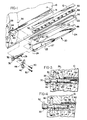
- Fig. 1 shows a portion of a typical rotary cutter cylinder 10 to which may be mounted a blade 12 of any length up to and including the length of the cylinders.
- Blade 12 is shown as a perforating blade, but alternatively may be a cutoff blade.
- the cylinder 10 includes a longitudinal recess 14 defined along the periphery of cylinder 10.
- Recess 14 is preferably rectangular is cross-section, and as seen in Fig. 6, includes a base 15 and opposed walls 16 and 18.
- blade 12 may be inserted into recess 14 of cylinder 10 for mounting, although blade 12 is not bottomed against base 15, allowing space both for crash-in and storage of blade 12 when not in use. Blade 12 is held in position by the blade holding device 20 embodying the present invention.
- Blade holding device 20 includes a pair of wedge members 22 and 24.
- Each wedge member 22 and 24 has an inner wedge face 23 and 25, respectively, and an outer face 26 and 27, respectively.
- wedge members 22 and 24 are tapered in a direction longitudinally along the recess 14. Further, wedge members 22 and 24 are insertable into recess 14 of cylinder 10 with wedge faces 23 and 25 in mutual contact, such that the blade 12 may be held between outer face 26 of wedge member 22 and wall 16 of recess 14. Wedge member 24 is moved relative to wedge member 22, applying a wedging force against both walls 16 and 18 of recess 14, thereby clamping blade 12 into position.
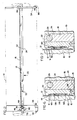
- Wedge member 24 is provided with a threaded bore 28 in one end thereof.
- Bolt 29, engageable with bore 28 includes a head 30 and a pair of flanges 32 and 34.
- An annular collar 36 attached to one end of cylinder 10 by a plurality of bolts 38 includes notch 40, communicating with recess 14 of cylinder 10.
- Notch 40 of collar 36 includes a relatively shallow portion 42 having a groove 44 defined therein.
- a retaining member 46 having a groove 48, is mounted to relatively shallow portion 42 by a pair of bolts 50.
- Grooves 44 and 48 cooperate to define a hole, and bolt 29 is fittable within the hole such that flanges 32 and 34 are disposed on each side of the hole.
- Grooves 44 and 48 are sized accordingly such that flanges 32 and 34 retain bolt 29 within the hole but bolt 29 is freely rotatable within the hole.
- bolt 29 may have a single flange, with the single flange and bolt head 30 cooperating at opposite ends of grooves 44 and 48 for retention of bolt 29 within the hole defined by grooves 44 and 48.
- FIG. 3 illustrates the wedge members 22 and 24 wedged into recess 14 of cylinder 10 such that blade 12 is securely held between outer face 26 of wedge member 22 and wall 16 of slot 14.
- head 30 of bolt 29 is gripped by an appropriate tool (not shown) and bolt 29 is rotated in the direction indicated by arrow 52 in Fig. 4.
- bolt 29 and bore 28 are provided with left-handed threads, and bolt 29 may have multiple start threads for faster movement of bolt 29 along bore 28, and hence, faster operation of the blade holding device 20.
- wedge member 24 By rotating within threaded bore 28 of wedge member 24, bolt 29 draws wedge member 24 in a direction toward collar 36, as indicated by arrow 53. As wedge member 24 is drawn toward collar 36, wedge members 22 and 24 no longer apply wedging force to the walls of recess 14, and blade 12 is released and may be removed.
- wedge member 22 remains stationary within recess 14, retained by collar 36 and an annular end ring 54 mounted to the opposite end of cylinder 10 from collar 36.
- each wedge member is provided with marks, notches or other indicia 55 to present a visual indication of their relative movement.
- any appropriate solid lubricant may be applied to the wedge face 25 and outer face 27 of wedge member 24.
- a relatively shallow channel 56 is defined along the length of the outer face 26 of wedge member 22, as seen in Fig. 1.
- a plurality of Belleville disc springs 58 are disposed along channel 56, and are held in relative position by a rubber strip 60.
- Rubber strip 60 includes a plurality of holes defined along its length, such that each spring 58 may be mounted within one of the holes and retained thereby. Springs 58 may be held into the holes of strip 60 either by cementing them in place, such as with a rubber cement, or molding the strip 60 about the springs 58 so that they are retained in place. Strip 60 is preferably mounted to channel 56 by a rubber cement material.
- Surfaces 61 may be roughened or knurled to provide increased holding force, by friction, for the blade 12 to prevent its slippage within recess 14.
- springs 58 for providing relative ease in positioning wedge member 24 for crash-in of blade 12 may be seen by referring to Fig. 5, showing a plot of the load (force per unit length) placed upon the blade 12 by the blade holding device 20 as a function of the displacement of wedge member 24 along recess 14, and as a function of the compression of wedge members 22 and 24 and springs 58 across recess 14.
- the values presented along the load axis of Fig. 5 are pertinentto blades and blade holding devices in general, independent of their length, and values presented along the compression axis are similarly independent of the angle formed between the wedge face 25 and outer face 27 of the wedge member 24.
- Values presented along the displacement axis of Fig. 5, however, are dependent upon the wedge member angle, and specific values in Fig. 5 are based upon an exemplary angle of 1°. It will be nonetheless understood that the shapes and relationships of the curves presented are correct for any angle.
- springs 58 When springs 58 are provided as illustrated generally in Fig. 1, the displacement of wedge member 24 produces the load values indicated by curve 70 in Fig. 5. Initially, only springs 58 actually contact blade 12, as seen in Fig. 7, and as wedge member 24 is moved, springs 58 compress against blade 12. Springs 58 have a significantly lower force constant (or, more properly here, a spring constant), approximately 6679 Kg/cm 2 (95,000 Ibs./in 2 ), than wedge members 22 and 24, and the initial portion of curve 70, indicated at 72, has a proportionately reduced slope.
- portion 76 of curve 70 After springs 58 are compressed such that surfaces 61 of wedge member 22 contact blade 12, further displacement of wedge member 24 causes the load to increase as shown by portion 76 of curve 70. Since portion 76 has a significantly increased slope compared to portion 72, relatively little additional displacement is necessary to apply the final clamping load to blade 12.
- a number of alternative embodiments for the spring members may be used in place of springs 58 and rubber strip 60, each having the same operation as the embodiment just disclosed and producing a load-displacement curve of the same shape as curve 70.
- a single corrugated metal strip 78 is provided, fittable within channel 56 of wedge member 22.
- a continuous elastomeric strip 80 is used, mounted to channel 56 by a rubber cement material.
- a series of slightly compressible rollers or balls may be placed between the wedge members 22 and 24.
- spring members may be used that are characterized by a non-linear compression-load relationship. Such an embodiment will produce a curve somewhat different from curve 70, in that the portion corresponding to portion 72 will not be linear, but will nontheless result in expansion of the compression and displacement ranges for crash-in, thereby obtaining the same advantages.
- Ring 54 is attached to cylinder 10 by a plurality of screws 86 (only one shown) and is of a radial width less than the depth of recess 14.
- a retaining pin 88 is mounted near the lower end of each of wedge members 22 and 24, such that when wedge members 22 and 24 are inserted into recess 14, retaining pins 88 extend from recess 14 under the ring 54.
- retaining pins 88 cooperate with ring 54 to hold the wedge members in place.
- a similar retaining pin 88 is provided at the opposite end of wedge member 22, and is inserted into a half-slot (not shown) defined within collar 36. It will be seen that no retaining pin is required for the opposite end of wedge member 24, due to its engagement with bolt 29.
- the device hereinbefore described and illustrated enables the blade to be initially secured sufficiently to allow it to seat against an anvil surface, and then be clamped to secure the blade for perforation of a web.
- the device exerts a uniform crash in or clamping force along the entire length of the blade.
- the device is relatively quick and simple to operate, is relatively easy to manufacture, and may be applied to cylinders having a standard configuration for the recess defined therein.
Landscapes
- Engineering & Computer Science (AREA)
- Mechanical Engineering (AREA)
- Life Sciences & Earth Sciences (AREA)
- Forests & Forestry (AREA)
- Perforating, Stamping-Out Or Severing By Means Other Than Cutting (AREA)
Description
- The present invention relates to a device for mounting and accurately seating a perforating or cutoff blade along a cylinder such as might be used for partially or completely severing a web at a plurality of locations along its length. Such devices are particularly useful in machines for continuous printing or collating of paper webs.
- One of the requirements for such blade mounting arrangements is that the blade be capable of removal, replacement and/or repositioning along the rotating blade cylinder. From time to time during the operation of the machine, it is necessary to remove the blade from the cylinder, for instance, when it may be desired to print a web without perforating or severing the same, or when replacement of the blade is necessary due to dulling or breakage of the blade.
- A second requirement for such blade mounting arrangements is that the cutting edge of a perforating blade be capable of accurate seating against an anvil surface. Otherwise, an uneven perforation will result, with some sections of the perforation being too deep, or some sections being too shallow, or both. This produces variation in the tear strength along the perforation, with resultant high probability of jamming in subsequent printers or bursters. A backup or anvil cylinder may be included for providing a hardened anvil surface, or insert, or in some cases a die, to cooperate with the sharpened edge of the properly seated blade in perforating the passing web as the web moves between the rotating blade cylinder and anvil or backup cylinder.
- The blade is mounted to the rotating cylinder by clamping the blade into a recess or slot cut generally lengthwise into the cylinder periphery. Typically, the recess is rectangular in cross section, and the blade may be clamped against one of the side faces of the recess, or against an intermediate supporting bar. Several techniques are available, however, for providing proper seating of the cutting edge of the blade against the anvil surface.
- Typically, when a perforating blade is manufactured, it includes some variation in height from its base to its cutting edge, as well as a tendency to bow in a lateral direction. One method for seating the blade is to use a blade which has been manufactured to very close tolerances with respect to both height and bow. The cylinder is provided with a recess that has been machined also to very close tolerances with respect to a uniform and specific depth. Seating of the blade is relatively simple, since the blade is loaded into the recess, with the base of the blade bottomed along the base of the recess, and is then clamped tightly in place.
- Despite the simplicity of the seating process, this technique possesses several readily apparent disadvantages. By requiring very close tolerances in manufacturing of the blades, the cost of the blades is increased significantly. Similarly, the cost of the cylinder into which the recess is cut is also increased, particularly in view of the fact that such cylinders typically have as many as eight such recesses for mounting up to eight blades at one time. Moreoever, in the event that blade height or recess depth varies even slightly from blade to blade or recess to recess, the cutting edge of a blade extending slightly further from the recess than another will be dulled relatively quickly through contact with the anvil surface.
- A second technique is available, in which a blade having very loose height and bow tolerance may be used. The blade is inserted into the recess, but is not bottomed against the base of the recess, and is secured somewhat loosely along its length. The blade is then seated against the anvil surface, through a procedure known as "crash in". This procedure consists of rotating the blade cylinder and anvil cylinder, with or without a web passing therebetween at inching speed through one revolution. The cutting edge of the blade is free to move under the seating force sufficiently into the recess, at whatever locations are necessary to obtain a uniform seating of the cutting edge against the anvil. While secured somewhat loosely, the blade must be nonetheless held tight enough to hold its seated position. The apparatus is then stopped and the blade is securely clamped along its entire length to prevent slip within the recess when the apparatus is operated at higher speeds.
- While this technique requires a more complicated blade seating technique, it allows the use of blades and cylinders manufactured to much looser tolerances, with substantial cost savings. A third technique, possessing some of the advantages and disadvantages of both techniques, utilizes a blade having close tolerance with respect to height only. While the blade is bottomed against the recess base, crash-in is required to remove vertical bow from the blade.
- It will be noted that the foregoing discussion is equally applicable in the case of cut-off blades.
- A number of various devices for accurately securing a blade within a recess, suitable for holding the blade both for crash-in and for clamping, are known. For instance, the blade may be placed against a side wall of the recess, and a bar inserted into the recess adjacent the blade. A plurality of bolt members are threaded into holes in the bar, extending from the side of the bar to the recess side wall opposite the blade. To clamp the blade, the bolt members are driven in a direction outwardly from the bar against the recess wall. Driving of the bolt members forces the bar tightly against the blade, thereby clamping it in place. In using such a device, the bolt members may be partially tightened, allowing the blade limited movement for seating against the anvil surface during crash-in, and then the bolt members may be completely tightened for clamping.
- Several disadvantages are present in such a blade holding device. In order to provide relatively uniform clamping force on the blade, a relatively large number of the bolt members must be provided disposed along the length of the bar. Thus, the clamping operation becomes a time-consuming process. Furthermore, positioning of the bolt members for crash-in must be fairly precise, since there is a relatively narrow force range suitable for crash-in wherein the blade is held loosely enough for movement during seating but tight enought to retain the seated position. Furthermore the bolt members also must be finally tightened to a relatively uniform degree, or uneven perforation will result where the blade is inadequately clamped. Consequently, during crash-in and in clamping the blade, either a torque wrench must be used, or the operator must through experience develop a "feel" for the proper tightening of the bolt members.
- In U.S. patent No. 4,131,047, issured December 26, 1978, to Schriber et al, a blade holding device is disclosed in which a wedge bar is provided for clamping the blade into the cylinder recess. The blade is placed against a side wall of the recess, and the wedge bar is provided with a vertical taper, i.e., in a radial direction with respect to the cylinder. A non-rectangular cross-sectional recess may be provided, or an intermediate member placed between the blade and the wedge bar and having a taper opposite the wedge bar may be provided, along with a plurality of bolts extending through the wedge bar and into the cylinder at the bottom of the recess. By driving the bolts, the wedge bar is forced into the recess in a direction toward the axis of the cylinder, thereby securely clamping the blade into the recess. Preloading springs may be provided to act on the wedge bar with a force sufficient to retain the blade during crash-in while allowing limited movement of the blade within the recess for seating. Following seating, the bolts are tightened to firmly secure the blade.
- By providing the preloading springs for supplying sufficient clamping force for seating of the blade, the Schriber et al device eliminates the need for the operator to manipulate the bolts during the crash in process. Additionally, by providing bolts that are driven radially with respect to the cylinder, rather than disposed within the-recess, access to the bolts is facilitated. Nonetheless, the Schriber et al device utilizes a plurality of bolts to provide a relatively uniform clamping force on the blade. Moreover, since the bolts are disposed along the entire length of the wedge bar, the operator must reach along the full length of the cylinder during the clamping process. Thus, even with the Schriber et al blade holding device, the clamping process is both time-consuming and awkward to perform.
- In U.S. patent No. 2,832,411, issued April 29, 1958, to Richards et al, another blade holding device is disclosed, for use in conjunction with a cylinder having a recess that is at an angle with respect to the axis of the cylinder. A pair of wedge bars, each extending for substantially the full length of the recess, are located within the recess with the blade inserted between the bars. The ends of the cylinder are provided with collars, each having a slot adjacent the recess, into which a bolt is fitted. The bolts each have a pair of flanges near the head, and when the bolts are placed into the slots, the flanges fit one on each side of the slot. Each bolt extends into a threaded bore in an end of one of the wedge bars, such that by rotating the bolts, each bar may be moved in either direction along the cylinder recess. To clamp the blade, the bolts are rotated such that the wedge bars are driven into the recess so as to wedge the blade into place. Notches or other indicia are provided along the upper surface of one of the wedge bars and the cylinder surface, so that the relative movement of the bar in relation to the cylinder for aligning the blade may be easily determined.
- The Richards et al device reduces the number of bolts which must be manipulated during the clamping process in comparison with the devices described above. It is indicated in the patent, however, that the primary purpose of the device is to enable the angle of the blade with respect to the direction of travel of the web to be somewhat adjustable, although the device seems better suited for adjusting the distance from the blade along the cylinder periphery to a next following blade. In either case, while such a feature may be desirable in compensating for an improperly machined cylinder and/or associated gears, it requires the operator of the device during the clamping process to ensure that the blade is mounted either precisely perpendicular to the web, or precisely to the required spacing from perforation to perforation or from separation to separation. Consequently, any reduction in complexity or time obtained through use of the Richards device is lost in the necessary adjustment of the blade angle or radial position. Further, by having bolt members extending from each end of the cylinder, the operator is required to travel around the machine during the clamping process as blade angle and position adjustments are made. Finally, use of the device requires a cylinder having a recess cut an angle with respect to the cylinder axis. To use this device, then, a specially constructed cylinder must be used.
- In addition, the Richards et al patent does not address the problem of holding the blade for seating during crash-in, and in fact, shows the blade bottomed on the recess base. Moreover, the Richards device possesses several disadvantages that make it impractical for use with a blade that must be seated for uniform perforation.
- Because the force exerted upon the blade must be substantially uniform to ensure uniform perforation, the fit of the wedge bars into the recess must be very precise. Thus very close tolerances must be provided in the widths of the wedge bars, recess, and blade, since variations in these dimensions will produce variations in the "tightness" of the fit of the wedge bars within the recess as the bars are wedged into place, thereby producing variations in the force applied to blade. As a result, not only is manufacture of the bars, recess and blade made difficult and expensive, but the slightest mishandling of these parts during use may be sufficient to misalign them to the extent that uniform force is no longer attainable.
- Further, since the range of force values acceptable for crash in is relatively narrow, careful positioning of the bars is required prior to crash-in. This requires the expenditure of significant amounts of time, use of special tools, and/or the development of special skills by the operator for proper adjustment of the bars.
- US-A-3793918, which is considered to represent the closest known prior art, discloses another blade holding device comprising a multiplicity of clamp rollers distributed along the recess with their axes disposed radially of the cylinder. The rollers are loose and shiftable transversely and longitudinally in the recess, and are disposed in two longitudinal rows with the peripheries of the rollers in one row projecting between and contacting the peripheries of the rollers in the other row. By applying a compressive force to the rollers longitudinally of the recess the two rows are cammed apart transversely, thereby to exert a clamping force on the blade at a plurality of locations along the length thereof. Whilst the device is claimed to be capable of quickly, accurately and uniformly clamping the blade in its operative position, it possesses the previously described disadvantage that there is only a relatively narrow clamping force range which is suitable for crash-in wherein the blade is held loosely enough for movement during seating but tight enough to retain the seated position.
- What is needed, therefore, is a blade holding device for use with a cylinder in which the blade may be clamped in a relatively quick and simple manner. Such a device should require manipulation of few parts during the clamping operation, and should not require the use of any special tools or special skills on the part of the operator. The device should enable the blade to be secured loosely into the cylinder with uniform securing force, properly seated against an anvil surface, and then tightly clamped into place. Clamping force should be uniformly applied along the length of the blade. The device should be relatively simple to manufacture, and should not require unreasonably tight manufacturing tolerances.
- It is an object of the present invention to provide a device for clamping a blade to a rotary cutter cylinder by means of which the blade may be inserted into and held in place by the device so that the blade may move as necessary to seat against an anvil surface during crash-in, whilst it is held so that it will be retained in the seated position. Thereafter, the blade holding device can be tightened in order to secure the blade in the seated position.
- According to the present invention, there is provided a blade holding device for use with a blade and a rotatable cylinder, the cylinder having a longitudinal recess defined in the periphery thereof parallel to the axis of the cylinder, members fittable within the recess with adjacent faces in mutual contact, such that the blade is disposed between the members and a waU of the recess, and means for performing relative movement of the members whereby the blade is clamped between the members and the recess wall, characterized in that:
- said members comprise first and second wedge members fittable within the recess, each said wedge member having an inner wedge face and an outer face, each of said wedge members being tapered in a direction longitudinal along said recess;
- said wedge members being insertable within the recess with said inner wedge faces in mutual contact, such that, in operation, the blade is disposed between said outer face of said first wedge member and a wall of the recess; and
- said movement performing means comprise means for performing relative movement between said wedge members in a direction along the recess, said first wedge member being operative in response to said movement to apply force to the blade for retaining the blade within the recess;
- means being provided for increasing said retaining force applied to the blade as a non-linear function of relative displacment between said wedge members.
- In one prefered embodiment, to ensure uniform holding force against the blade for crash-in, the retaining force-increasing means includes at least one spring member disposed adjacent the outer face of the first wedge member between the wedge member and the blade. In a further preferred embodiment, a plurality of spring members may be provided in the form of Belleville disc springs, although a spring member in the form of a corrugated metal strip or elastomeric strip may alternatively be used. The disc springs may be held in relative positions, and the holding means may be a strip constructed of a resilient material having a plurality of holes along the length thereof. The disc springs are mounted one each within each hole. The first wedge member includes a relatively shallow channel defined along the length of its outer face, so that the resilient strip may be mounted along the channel, whereby the disc springs may abut the blade, for example, perforating blade, when the blade and first wedge member are inserted into the recess of the cylinder.
- Inclusion of the spring members provides a wide range for relative positioning of the wedge members for crash-in. Because the range of holding force exerted upon the blade for proper seating is relatively narrow, the spring members make application of the proper force easier, faster, and more precise than in previously known devices.
- The spring members also allow a wider range of tolerance for the recess or slot width, wedge member width and blade thickness, and produce more uniform crash-in force along the entire length of the blade.
- The relative movement of the wedge members within the cylinder recess may be performed by providing an end member mounted to one end of the cylinder adjacent the recess. The end member includes an opening therein, through which a bolt is extended. The bolt has at least one flange near its head, the flange being disposed on one side of the opening for retaining the bolt in a position relative to the end member. The bolt is further engageable with one of the wedge members, so that by rotating the bolt, the wedge member. may be move relative to the cylinder, and hence relative to the other wedge member.
- The bolt may be engageable with an end of the second wedge member, and the relative movement of the wedge members is performed by moving the second wedge member along the recess. The first wedge member is captured between two end rings to prevent its movement along the recess. Additionally, at least a portion of the outer face of the first wedge member is roughened to increase the holding force on the blade or to prevent slippage of the blade within the recess.
- In order that the invention may be more readily understood, reference will now be made to the accompanying drawings, in which:
- Fig. 1 is a perspective view of a portion of a rotary cutter cylinder showing insertion into a recess therein of a blade and the blade holding device embodying the present invention;
- Fig. 2 is a plan view of the cylinder showing the blade and blade holding device in position;
- Fig. 3 is a sectional view of a portion of one end of the cylinder, showing the wedging mechanism for operating the blade holding device with the blade firmly clamped in place;
- Fig. 4 is a view similar to Fig. 3 showing the operation of the wedging mechanism and with the blade in position for seating within the recess;
- Fig. 5 is a graph showing the load applied to the perforating blade as a function of displacement of a wedge member along the recess, and as a function of the compression of the wedge members and spring members across the recess;
- Fig. 6 is an enlarged cross-sectional view of a segment of the cylinder, taken generally along line 6-6 of Fig. 3;
- Fig. 7 is a view similar to Fig. 6, taken generally along line 7-7 of Fig. 4;
- Fig. 8 is a perspective view of a portion of a wedge member, showing an alternative embodiment for the spring member; and
- Fig. 9 is a cross-sectional view similar to a portion of Fig. 6, showing a further alternative embodiment for the spring member.
- Fig. 1 shows a portion of a typical
rotary cutter cylinder 10 to which may be mounted ablade 12 of any length up to and including the length of the cylinders.Blade 12 is shown as a perforating blade, but alternatively may be a cutoff blade. Thecylinder 10 includes alongitudinal recess 14 defined along the periphery ofcylinder 10.Recess 14 is preferably rectangular is cross-section, and as seen in Fig. 6, includes abase 15 and opposedwalls blade 12 may be inserted intorecess 14 ofcylinder 10 for mounting, althoughblade 12 is not bottomed againstbase 15, allowing space both for crash-in and storage ofblade 12 when not in use.Blade 12 is held in position by theblade holding device 20 embodying the present invention. -
Blade holding device 20 includes a pair ofwedge members wedge member inner wedge face outer face wedge members recess 14. Further,wedge members recess 14 ofcylinder 10 with wedge faces 23 and 25 in mutual contact, such that theblade 12 may be held betweenouter face 26 ofwedge member 22 andwall 16 ofrecess 14.Wedge member 24 is moved relative towedge member 22, applying a wedging force against bothwalls recess 14, thereby clampingblade 12 into position. - The means for effecting movement of
wedge member 24 with respect towedge member 22 may be seen in Fig. 1, 3 and 4.Wedge member 24 is provided with a threadedbore 28 in one end thereof.Bolt 29, engageable withbore 28 includes ahead 30 and a pair offlanges annular collar 36 attached to one end ofcylinder 10 by a plurality ofbolts 38 includesnotch 40, communicating withrecess 14 ofcylinder 10. Whenwedge member 24 is inserted intorecess 14, andbolt 29 is threaded intobore 28,notch 40 provides for extension ofhead 30 ofbolt 29 beyondcollar 36, so as to allow manipulation ofbolt 29 from a position adjacent one end ofcylinder 10. -
Notch 40 ofcollar 36 includes a relativelyshallow portion 42 having agroove 44 defined therein. A retainingmember 46, having agroove 48, is mounted to relativelyshallow portion 42 by a pair ofbolts 50.Grooves bolt 29 is fittable within the hole such thatflanges Grooves flanges retain bolt 29 within the hole butbolt 29 is freely rotatable within the hole. - In the alternative, of course, it will be recognized that
bolt 29 may have a single flange, with the single flange andbolt head 30 cooperating at opposite ends ofgrooves bolt 29 within the hole defined bygrooves - The operation of
bolt 29 for movingwedge member 24 relative to wedgemember 22 may be seen by comparing Figs. 3 and 4. Fig. 3 illustrates thewedge members recess 14 ofcylinder 10 such thatblade 12 is securely held betweenouter face 26 ofwedge member 22 andwall 16 ofslot 14. To releaseblade 12,head 30 ofbolt 29 is gripped by an appropriate tool (not shown) andbolt 29 is rotated in the direction indicated byarrow 52 in Fig. 4. It will be noted fromarrow 52 thatbolt 29 and bore 28 are provided with left-handed threads, and bolt 29 may have multiple start threads for faster movement ofbolt 29 alongbore 28, and hence, faster operation of theblade holding device 20. By rotating within threaded bore 28 ofwedge member 24,bolt 29 drawswedge member 24 in a direction towardcollar 36, as indicated byarrow 53. Aswedge member 24 is drawn towardcollar 36,wedge members recess 14, andblade 12 is released and may be removed. - It will be recognized that to move
wedge member 24 for clampingblade 12 intorecess 14, the opposite of the operation described above is performed.Bolt 29 is rotated in a direction opposite to that indicated byarrow 52, thereby movingwedge member 24 away frombolt 29.Wedge members recess 14, clampingblade 12 into place. - During either of these operations,
wedge member 22 remains stationary withinrecess 14, retained bycollar 36 and anannular end ring 54 mounted to the opposite end ofcylinder 10 fromcollar 36. - It can easily be seen that the force or load applied to
blade 12 byblade holding device 20 is dependent upon compression ofwedge members recess 14, which in turn is dependent upon the displacement ofwedge member 24 alongrecess 14. Accordingly, as an aid to the operator of thedevice 20 inpositioning wedge member 24 relative to wedgemember 22, which remains stationary, each wedge member is provided with marks, notches orother indicia 55 to present a visual indication of their relative movement. - To facilitate the movement of
wedge member 24 relative to and in contact withwedge member 22 andrecess 14, any appropriate solid lubricant may be applied to thewedge face 25 andouter face 27 ofwedge member 24. - During crash-in of
blade 12 for proper seating withinrecess 14 to provide a uniform perforation or severing of a web passing alongcylinder 10, force must be applied toblade 12 by theblade holding device 20 within a relatively narrow range of forces so thatblade 12 is held loosely enough to permit seating, yet tightly enough to retain the seated position prior to final clamping. In order to expand the range of positions ofwedge member 24 relative to wedgemember 22 andrecess 14 wherein force within the crash-in range is applied toblade 12, a relativelyshallow channel 56 is defined along the length of theouter face 26 ofwedge member 22, as seen in Fig. 1. A plurality of Belleville disc springs 58 are disposed alongchannel 56, and are held in relative position by arubber strip 60.Rubber strip 60 includes a plurality of holes defined along its length, such that eachspring 58 may be mounted within one of the holes and retained thereby.Springs 58 may be held into the holes ofstrip 60 either by cementing them in place, such as with a rubber cement, or molding thestrip 60 about thesprings 58 so that they are retained in place.Strip 60 is preferably mounted to channel 56 by a rubber cement material. - As seen in Figs. 6 and 7, during clamping of
blade 12, springs 58, held in place bystrip 50, are gradually compressed againstblade 12 aswedge member 24 is wedged intorecess 14. Once springs 58 are compressed to the point at which surfaces 61 ofwedge member 22 are in contact withblade 12, however, further movement ofwedge member 24 results inblade 12 being clamped essentially by thewedge members -
Surfaces 61 may be roughened or knurled to provide increased holding force, by friction, for theblade 12 to prevent its slippage withinrecess 14. - The operation of
springs 58 for providing relative ease inpositioning wedge member 24 for crash-in ofblade 12 may be seen by referring to Fig. 5, showing a plot of the load (force per unit length) placed upon theblade 12 by theblade holding device 20 as a function of the displacement ofwedge member 24 alongrecess 14, and as a function of the compression ofwedge members recess 14. It will be recognized that the values presented along the load axis of Fig. 5 are pertinentto blades and blade holding devices in general, independent of their length, and values presented along the compression axis are similarly independent of the angle formed between thewedge face 25 andouter face 27 of thewedge member 24. Values presented along the displacement axis of Fig. 5, however, are dependent upon the wedge member angle, and specific values in Fig. 5 are based upon an exemplary angle of 1°. It will be nonetheless understood that the shapes and relationships of the curves presented are correct for any angle. - It has been found experimentallythatthe proper load to be placed upon
blade 12 for satisfactory crash-in is within the approximate range of 41.25 to 84.83 Kg/cm (231 to 475Ibs.lin.), indicated in Fig. 5 byarrow 64. Forfinal clamping ofblade 12, a load of at least 250 Kg/cm. (1400 ibs./in.) must be applied, indicated at 66. - In the absence of
springs 58, the load produced by deflection ofwedge member 24, corresponding to direct compression ofwedge members wedge members curve 68 of Fig. 5. For crash-in,wedge member 24 must be moved between approximately 0.76 and 1.52 mm. (.03 and .06 inches) to produce a load onblade 12 within the appropriate range. It can easily be seen, however, that positioning ofwedge member 24 must necessarily be relatively precise, i.3., to within a range of .76 mm. (.03 inch), in order to achieve the proper crash-in load. With such a small range, even indicia 55 are of relatively little help for proper positioning. Thus, special tools for adjustingbolt 29 must be used or the operator of thedevice 20 must develop special skills or expertise. - When springs 58 are provided as illustrated generally in Fig. 1, the displacement of
wedge member 24 produces the load values indicated bycurve 70 in Fig. 5. Initially, only springs 58 actuallycontact blade 12, as seen in Fig. 7, and aswedge member 24 is moved, springs 58 compress againstblade 12.Springs 58 have a significantly lower force constant (or, more properly here, a spring constant), approximately 6679 Kg/cm2 (95,000 Ibs./in2), thanwedge members curve 70, indicated at 72, has a proportionately reduced slope. - Once springs 58 are compressed such that surfaces 61 of
wedge member 22contact blade 12, indicated atpoint 74 oncurve 70, further displacement ofwedge member 24 causes increases in the load onblade 12 to be applied bywedge members final portion 76 ofcurve 70 is of the same slope ascurve 68. - The effect of
springs 58 upon the operation ofblade holding device 20 for applying crash-in force toblade 12 may be appreciated by considering the crash-inload range 64. To apply the proper load,wedge member 24 must be moved between approximately 3.56 and 7.11 mm (.14 and .28 inches), or within a range of 3.56 mm. (.14 inch), as indicated at 77. Thus, a relatively broad range of positions is available forwedge member 24, making the use ofindicia 55 much more practical and helpful. Since positioning ofwedge member 24 is no longer so critical, no special tools or operator expertise is required for operatingblade holding device 20. - After
springs 58 are compressed such that surfaces 61 ofwedge member 22contact blade 12, further displacement ofwedge member 24 causes the load to increase as shown byportion 76 ofcurve 70. Sinceportion 76 has a significantly increased slope compared toportion 72, relatively little additional displacement is necessary to apply the final clamping load toblade 12. - An additional, if not more important, advantage may be obtained through use of the spring members as provided in any of the embodiments disclosed above. In the absence of spring members, very close tolerances must be provided to insure the uniformity of the widths of the
wedge members recess 14, andblade 12, with the attendant high cost and extreme care required in handling these parts. Otherwise, because of the relative rigidity ofwedge members blade 12 of varying load exerted thereon, resulting in uneven perforation or severing of the web. The required tolerance may be seen from Fig. 5. The compression range within the crash-in range wherewedge member springs 58, shown oncurve 68 as range 69, is between .0127 and .0254 mm (.0005 and .0010 inch). If the tolerance on any one or a combination of wedge members, blade or recess is such that any area alongblade 12 is compressed outside this range, load applied will be outside the crash-in range, seating may not be accurate, and the resulting perforation or severing may be uneven. Thus, the tolerance required is .0254-.0127 mm.=0.0127 mm (.0010 inch-.0005 inch=.0005 inch). - Due to the relative flexibility imparted to the
blade holding device 20 by inclusion of one or more spring members, however, these tolerances may be relaxed. As shown at 77 alongcurve 70 of Fig. 5, when springs 58 are used, the compression range of wedge members and springs is between .061 and .127 mm. (.0024 and .0050 inch). Thus, inclusion ofsprings 58 allows wedge member, blade and recess tolerance to be increased to .066 mm (.0026 inch), a five-fold increase, with resulting significant cost savings in manufacture. - A number of alternative embodiments for the spring members may be used in place of
springs 58 andrubber strip 60, each having the same operation as the embodiment just disclosed and producing a load-displacement curve of the same shape ascurve 70. In Fig. 8, a singlecorrugated metal strip 78 is provided, fittable withinchannel 56 ofwedge member 22. In Fig. 9, a continuous elastomeric strip 80 is used, mounted to channel 56 by a rubber cement material. A series of slightly compressible rollers or balls may be placed between thewedge members - It will also be recognized that spring members may be used that are characterized by a non-linear compression-load relationship. Such an embodiment will produce a curve somewhat different from
curve 70, in that the portion corresponding toportion 72 will not be linear, but will nontheless result in expansion of the compression and displacement ranges for crash-in, thereby obtaining the same advantages. - It is common practice to rotate the
cylinder 10 on occasion when it'is desired not to perforate or sever the web. In such a case, theblade holding device 20 is unclamped,blade 12 is bottomed againstrecess base 15 so that the cutting edge ofblade 12 is below the surface ofcylinder 10, and thedevice 20 is reclamped. In theevent device 20 is inadvertently left unclamped, however, a means for retainingwedge members recess 14 when unclamped is provided. In addition tocollar 36 mounted to one end ofcylinder 10, theannular ring 54 is provided at the opposite end seen in Fig. 2.Ring 54 is attached tocylinder 10 by a plurality of screws 86 (only one shown) and is of a radial width less than the depth ofrecess 14. A retainingpin 88 is mounted near the lower end of each ofwedge members wedge members recess 14, retaining pins 88 extend fromrecess 14 under thering 54. Whencylinder 10 is rotated withwedge members pins 88 cooperate withring 54 to hold the wedge members in place. Asimilar retaining pin 88 is provided at the opposite end ofwedge member 22, and is inserted into a half-slot (not shown) defined withincollar 36. It will be seen that no retaining pin is required for the opposite end ofwedge member 24, due to its engagement withbolt 29. - The device hereinbefore described and illustrated enables the blade to be initially secured sufficiently to allow it to seat against an anvil surface, and then be clamped to secure the blade for perforation of a web. The device exerts a uniform crash in or clamping force along the entire length of the blade. Furthermore, the device is relatively quick and simple to operate, is relatively easy to manufacture, and may be applied to cylinders having a standard configuration for the recess defined therein.
- While the form of device herein described constitutes a preferred embodiment of this invention, it is to be understood that the invention is not limited to this precise form of device, and that changes may be made therein without departing from the scope of the invention as defined in the appended claims.
Claims (18)
Applications Claiming Priority (4)
| Application Number | Priority Date | Filing Date | Title |
|---|---|---|---|
| US38430282A | 1982-06-01 | 1982-06-01 | |
| US383865 | 1982-06-01 | ||
| US06/383,865 US4475425A (en) | 1982-06-01 | 1982-06-01 | Blade holding device |
| US384302 | 1995-02-03 |
Publications (3)
| Publication Number | Publication Date |
|---|---|
| EP0095912A2 EP0095912A2 (en) | 1983-12-07 |
| EP0095912A3 EP0095912A3 (en) | 1984-02-22 |
| EP0095912B1 true EP0095912B1 (en) | 1988-03-23 |
Family
ID=27010360
Family Applications (1)
| Application Number | Title | Priority Date | Filing Date |
|---|---|---|---|
| EP83303078A Expired EP0095912B1 (en) | 1982-06-01 | 1983-05-27 | Blade holding device |
Country Status (3)
| Country | Link |
|---|---|
| EP (1) | EP0095912B1 (en) |
| CA (1) | CA1206374A (en) |
| DE (1) | DE3376058D1 (en) |
Families Citing this family (5)
| Publication number | Priority date | Publication date | Assignee | Title |
|---|---|---|---|---|
| FR2619526B1 (en) * | 1987-08-19 | 1992-08-28 | Moore Business Forms Inc | DEVICE FOR SHAPING A WEB OF MATERIAL SUCH AS PAPER |
| SE469940B (en) * | 1992-01-14 | 1993-10-11 | Rolf Arne Larsson | Device for holding knife blades in a cylinder intended for machining a running track |
| EP0879680A3 (en) * | 1997-04-22 | 1999-11-03 | Heinrich Prof. Dr. Ing. Feichtinger | Mounting means for the knives of a rotor cutter |
| GB2332165B (en) * | 1997-12-13 | 2001-09-05 | T & S Engineering Company | Device and method for securing blades |
| CN109015854B (en) * | 2018-08-14 | 2023-09-05 | 杭州中为光电技术有限公司 | Cutter head floating mechanism of edge trimmer |
Citations (2)
| Publication number | Priority date | Publication date | Assignee | Title |
|---|---|---|---|---|
| US1137216A (en) * | 1914-05-02 | 1915-04-27 | Carl J Klingborg | Cutter-head. |
| EP0073595A2 (en) * | 1981-08-22 | 1983-03-09 | Wadkin Public Limited Company | Rotary cutter heads |
Family Cites Families (4)
| Publication number | Priority date | Publication date | Assignee | Title |
|---|---|---|---|---|
| US2832411A (en) * | 1954-12-13 | 1958-04-29 | Bonnar Vawter Inc | Perforating blade holding means |
| US3709077A (en) * | 1971-03-01 | 1973-01-09 | Bretting C Mfg Co Inc | Cut-off device |
| US3793918A (en) * | 1971-10-12 | 1974-02-26 | H Huffman | Cross perforating blade lock |
| US4131047A (en) * | 1977-03-28 | 1978-12-26 | Harris Corporation | Rotary knife mounting |
-
1983
- 1983-05-27 DE DE8383303078T patent/DE3376058D1/en not_active Expired
- 1983-05-27 EP EP83303078A patent/EP0095912B1/en not_active Expired
- 1983-05-31 CA CA000429327A patent/CA1206374A/en not_active Expired
Patent Citations (2)
| Publication number | Priority date | Publication date | Assignee | Title |
|---|---|---|---|---|
| US1137216A (en) * | 1914-05-02 | 1915-04-27 | Carl J Klingborg | Cutter-head. |
| EP0073595A2 (en) * | 1981-08-22 | 1983-03-09 | Wadkin Public Limited Company | Rotary cutter heads |
Also Published As
| Publication number | Publication date |
|---|---|
| CA1206374A (en) | 1986-06-24 |
| EP0095912A2 (en) | 1983-12-07 |
| EP0095912A3 (en) | 1984-02-22 |
| DE3376058D1 (en) | 1988-04-28 |
Similar Documents
| Publication | Publication Date | Title |
|---|---|---|
| US4475425A (en) | Blade holding device | |
| US3707303A (en) | Means for securing an insert to a base piece | |
| DE3685910T2 (en) | ROTATING CUTTER FOR PAPER. | |
| US4131047A (en) | Rotary knife mounting | |
| EP1136158B1 (en) | Cutting insert holder for turning tools and grooving insert therefor | |
| EP2724817A1 (en) | Clamping jaw or clamping element | |
| EP0095912B1 (en) | Blade holding device | |
| US3793918A (en) | Cross perforating blade lock | |
| US2431566A (en) | Die | |
| CA1054511A (en) | Roll fed rotary web device with improved perforator | |
| US3628246A (en) | Apparatus for tube removal | |
| US4715250A (en) | Rotary cutting cylinder and method of making same | |
| US4187753A (en) | Knife drum for cross cutting machines | |
| EP1136162B1 (en) | Facing- and corner milling cutter | |
| US4998829A (en) | Rotary die slot adjustable gib assembly | |
| DE10261967A1 (en) | mandrel | |
| EP0800898A2 (en) | Knife assembly for rotary cutting system | |
| US1986036A (en) | Perforating die and stripping mechanism therefor | |
| US3205732A (en) | Rotary cutting die | |
| US4561163A (en) | Fitting doctor blades | |
| US5642646A (en) | Method for manufacturing rotary cutting tool and rotary cutting tool | |
| US3729806A (en) | Method for tube removal | |
| DE69211672T2 (en) | Cutting device | |
| US2599818A (en) | Apparatus for driving wedges in armature slots | |
| DE10224839A1 (en) | Drive system for mandrel carrying roll of paper has retainer on inner circumference of roll and carrier elements transmitting torque to roll and engaging with roll in non-positive manner |
Legal Events
| Date | Code | Title | Description |
|---|---|---|---|
| PUAI | Public reference made under article 153(3) epc to a published international application that has entered the european phase |
Free format text: ORIGINAL CODE: 0009012 |
|
| AK | Designated contracting states |
Designated state(s): DE FR GB IT |
|
| PUAL | Search report despatched |
Free format text: ORIGINAL CODE: 0009013 |
|
| AK | Designated contracting states |
Designated state(s): DE FR GB IT |
|
| 17P | Request for examination filed |
Effective date: 19840816 |
|
| GRAA | (expected) grant |
Free format text: ORIGINAL CODE: 0009210 |
|
| AK | Designated contracting states |
Kind code of ref document: B1 Designated state(s): DE FR GB IT |
|
| ITF | It: translation for a ep patent filed | ||
| REF | Corresponds to: |
Ref document number: 3376058 Country of ref document: DE Date of ref document: 19880428 |
|
| ET | Fr: translation filed | ||
| PLBE | No opposition filed within time limit |
Free format text: ORIGINAL CODE: 0009261 |
|
| STAA | Information on the status of an ep patent application or granted ep patent |
Free format text: STATUS: NO OPPOSITION FILED WITHIN TIME LIMIT |
|
| 26N | No opposition filed | ||
| ITPR | It: changes in ownership of a european patent |
Owner name: CESSIONE;AM INTERNATIONAL INCORPORATED |
|
| REG | Reference to a national code |
Ref country code: FR Ref legal event code: TP |
|
| REG | Reference to a national code |
Ref country code: GB Ref legal event code: 732 |
|
| PGFP | Annual fee paid to national office [announced via postgrant information from national office to epo] |
Ref country code: GB Payment date: 19910523 Year of fee payment: 9 |
|
| PGFP | Annual fee paid to national office [announced via postgrant information from national office to epo] |
Ref country code: FR Payment date: 19910528 Year of fee payment: 9 |
|
| ITTA | It: last paid annual fee | ||
| PGFP | Annual fee paid to national office [announced via postgrant information from national office to epo] |
Ref country code: DE Payment date: 19910531 Year of fee payment: 9 |
|
| PG25 | Lapsed in a contracting state [announced via postgrant information from national office to epo] |
Ref country code: GB Effective date: 19920527 |
|
| GBPC | Gb: european patent ceased through non-payment of renewal fee |
Effective date: 19920527 |
|
| PG25 | Lapsed in a contracting state [announced via postgrant information from national office to epo] |
Ref country code: FR Effective date: 19930129 |
|
| PG25 | Lapsed in a contracting state [announced via postgrant information from national office to epo] |
Ref country code: DE Effective date: 19930202 |
|
| REG | Reference to a national code |
Ref country code: FR Ref legal event code: ST |