EP0095868B1 - A sub-caliber projectile - Google Patents
A sub-caliber projectile Download PDFInfo
- Publication number
- EP0095868B1 EP0095868B1 EP83302867A EP83302867A EP0095868B1 EP 0095868 B1 EP0095868 B1 EP 0095868B1 EP 83302867 A EP83302867 A EP 83302867A EP 83302867 A EP83302867 A EP 83302867A EP 0095868 B1 EP0095868 B1 EP 0095868B1
- Authority
- EP
- European Patent Office
- Prior art keywords
- sabot
- projectile
- retaining
- stabilizing member
- tail end
- Prior art date
- Legal status (The legal status is an assumption and is not a legal conclusion. Google has not performed a legal analysis and makes no representation as to the accuracy of the status listed.)
- Expired
Links
Images

Classifications
-
- F—MECHANICAL ENGINEERING; LIGHTING; HEATING; WEAPONS; BLASTING
- F42—AMMUNITION; BLASTING
- F42B—EXPLOSIVE CHARGES, e.g. FOR BLASTING, FIREWORKS, AMMUNITION
- F42B10/00—Means for influencing, e.g. improving, the aerodynamic properties of projectiles or missiles; Arrangements on projectiles or missiles for stabilising, steering, range-reducing, range-increasing or fall-retarding
- F42B10/02—Stabilising arrangements
- F42B10/12—Stabilising arrangements using fins longitudinally-slidable with respect to the projectile or missile
-
- F—MECHANICAL ENGINEERING; LIGHTING; HEATING; WEAPONS; BLASTING
- F42—AMMUNITION; BLASTING
- F42B—EXPLOSIVE CHARGES, e.g. FOR BLASTING, FIREWORKS, AMMUNITION
- F42B14/00—Projectiles or missiles characterised by arrangements for guiding or sealing them inside barrels, or for lubricating or cleaning barrels
- F42B14/06—Sub-calibre projectiles having sabots; Sabots therefor
- F42B14/061—Sabots for long rod fin stabilised kinetic energy projectiles, i.e. multisegment sabots attached midway on the projectile
Definitions
- This invention relates to a sub-caliber projectile _and is of particular applicability to so-called "arrow" or penetrator projectiles wherein there is a relatively high length to diameter ratio and wherein the central body section of the projectile is of substantially uniform diameter.
- sub-caliber projectiles are provided with detachable sabots which serve to locate centrally the sub-caliber projectile in a larger bored launching weapon and which, together with the projectile serve to absorb the propellant force so as to result in the effective projection of the projectile out of the launching weapon at high velocity.
- the sabot and its coupling to the projectile must be such that the sabot or its component parts are detached from the projectile once the latter has left the bore of the launching weapon.
- the projectile is provided with a radially enlarged stabilizing tail portion
- the sabot can clearly not disengage itself from the projectile by passing over the tail portion and means are provided to ensure that the sabot components are displaced radially with respect to the projectile when the latter has left the launching weapon.
- the sabot which is entirely and solely constituted by the segments has a dual function, namely "to absorb the forward thrust of propellant pressure” and “transmit it effectively to the projectile body" (column 1, lines 62-64) by means of the cooperating buttress grooves and also to save the "fins from having their surfaces eroded as has occurred when the sabot is placed in front of the fins" (column 2, lines 8-10).
- the sabot segments of US-A-3,125,957 become simultaneously and radially detached and this radial detachment has an undesirable hydro-dynamic effect on the flight characteristics of the projectile.
- the fins With the detachment of the sabot segments, the fins are free to be displaced rearwardly under the influence of air pressure.
- the air flow merely passes through the fins and the effectiveness of the air forces in rapidly displacing the fins.to the rearward stabilizing position of the projectile is substantially reduced.
- a sub-caliber projectile having a front end, a cylindrically shaped mid-section of substantially uniform diameter and having a tail end, at least the portion of the front end adjacent to said mid-section being of increased diameter with respect to the diameter of said mid-section so as to define an abutment shoulder adjacent the front end, and sabot means characterised in that the sabot means comprises an annular stabilizing member and an annular obturating disc member, first retaining means for releasably securing said members together, said sabot means being mounted on and being axially displaceable as a unit along said mid-section between a first position wherein said stabilizing member abuts said shoulder and a second position adjacent said tail end wherein said stabilizing member is retained and said obturating disc member is axially detached therefrom, and second retaining means, which may be the same as the first retaining means, for retaining said stabilizing member adjacent said tail end.
- the sabot means which consists of the stabilizing member and the obturating disc, move rearwardly as a single unit until they have reached the tail end of the projectile and as a consequence of this the disc continues to effect obturation with respect to the stabilizing member, thereby rendering much more efficient and speedy the rearward displacement of the stabilizing member to its final stabilizing position adjacent the tail end of the projectile.
- the sabot means which consists of the stabilizing member and the obturating disc, move rearwardly as a single unit until they have reached the tail end of the projectile and as a consequence of this the disc continues to effect obturation with respect to the stabilizing member, thereby rendering much more efficient and speedy the rearward displacement of the stabilizing member to its final stabilizing position adjacent the tail end of the projectile.
- only a single part of the original sabot means, namely the obturating disc is detached as compared with the plurality of segments which are detached in the case of US-A-3,125,
- the annular stabilizing member constitutes part of the sabot means and effectively supports the sabot obturating disc when the latter is disposed adjacent the front end of the projectile so as to take up the propellant force.
- the stabilizing member slides along the mid-section until it becomes located and retained in position adjacent the tail end so as to fulfill its stabilizing function during the flight of the projectile whilst at the same time the obturating disc becomes detached from the stabilizing portion passing over the tail end of the projectile.
- said first and second retaining means are constituted by a spring loaded retaining pin which when the sabot means is located in said first position couples said members together and when said sabot means is located in said second position enters a peripheral recess formed in said tail end so as to release said members and so as to retain said stabilizing member at the tail end.
- the said first retaining means may be constituted by shearable pins retaining said members together and wherein said second retaining means is constituted by a peripheral flange formed on said tail end against which said stabilizing member retainably abuts when in said second position.
- the invention also comprises sabot means for a sub-caliber projectile having a front end, a cylindrically shaped mid-section of substantially uniform diameter and having a tail end, at least the portion of the front end adjacent to said mid-section being of increased diameter with respect to the diameter of said mid-section so as to define an abutment shoulder adjacent the front end, characterised in that the sabot means comprises an annular stabilizing member and an annular obturating disc member, first retaining means for releasably securing said members together, said sabot means being adapted to be mounted on and axially displaceable as a unit along said mid-section between a first position wherein said stabilizing member abuts said shoulder and a second position adjacent said tail end wherein said stabilizing member is retained and said obturating disc member is axially detached therefrom, and second retaining means, which may be the same as the first retaining means, for retaining said stabilizing member adjacent said tail end.
- the sub-caliber projectile is of the penetrator kind where its length to diameter ratio is significantly high.
- the projectile is formed with an ogival front end 1, a tail end 2 formed with an annular peripheral recess 3 and a cylindrically shaped mid-section 4 of substantially-uniform diameter. The latter merges with the ogival front end 1 via an annular, abutment shoulder 5.
- the projectile is provided with sabot means 6, comprising an annular obturating disc 7 having a peripheral skirt 8 and a substantially cylindrical stabilizing member 9.
- the latter is formed with a plurality of throughgoing axially directed bores 10 and with a peripheral recess 11 into which is designed to fit the skirt 8.
- a radially directed bore 12 in which is located a spring loaded retaining pin 13.
- One end of the pin 13 is, as shown in Fig. 1 of the drawings spring biased into a locating bore formed in the skirt 8 and the other end bears against the mid-section 4.
- the forward end of the stabilizing member is tapered and is provided at its central planar end portion with a bearing disc 14.
- the sabot means 6 is clearly slidable along the mid-section 4 from a first position, wherein the bearing disc 14 bears against the abutment shoulder 5, to a second position wherein the innermost end of the spring loaded pin 13 enters the recess 3 thereby allowing for the detachment of the obturating disc 7 (as seen in Fig. 3 of the drawings).
- the sabot means 6 is also rotationally displaceable with respect to the mid-section 4.
- the obturating disc 7 supported and located by the stabilizing member9 effectively seals the bore and, upon firing, takes up the propulsion forces and as a consequence the projectile is launched with substantial initial velocity.
- the sabot means is displaced rearwardly along the cylindrical section 4 until the retaining pin 13 enters the recess 3 whereupon the obturating disc 7 is detached and is displaced rearwardly away from the projectile.
- the stabilizing portion 9 is retained in position at the tail end of the projectile and now performs a conventional function as a stabilizing tail.
- the tail end of the projectile is formed with an outwardly directed flange 17 whilst an annular obturating disc 18 is formed with its central aperture of greater diameter than that of the flange 17 and is located in an annular end recess formed in a stabilizing member 19 otherwise of similar construction to the stabilizing member shown in Fig. 1 of the drawings.
- the obturating disc 18 is secured to the stabilizing member 19 by means of shearable retaining pins 20.
- the incorporation of the stabilizing member in the sabot means and the retention thereof after firing in the correct position on the tail results in a considerable saving of weight. Furthermore, the fact that the detached obturating disc of the sabot means separates from the projectile in a rearward direction minimizes disturbance of the flight of the projectile as a result of the separation. Finally, the fact that the sabot means is rotationally displaceable with respect to the projectile ensures that any spin imparted to the sabot means is not necessarily transmitted to the projectile.
- the invention has been specifically described with respect to a stabilizing portion of substantially cylindrical shape, it is equally applicable when the stabilizing portion has other forms such as, for example, is formed with radially directed stabilizing fins.
Landscapes
- Engineering & Computer Science (AREA)
- General Engineering & Computer Science (AREA)
- Physics & Mathematics (AREA)
- Fluid Mechanics (AREA)
- Toys (AREA)
- Portable Nailing Machines And Staplers (AREA)
Description
- This invention relates to a sub-caliber projectile _and is of particular applicability to so-called "arrow" or penetrator projectiles wherein there is a relatively high length to diameter ratio and wherein the central body section of the projectile is of substantially uniform diameter. As is well known sub-caliber projectiles are provided with detachable sabots which serve to locate centrally the sub-caliber projectile in a larger bored launching weapon and which, together with the projectile serve to absorb the propellant force so as to result in the effective projection of the projectile out of the launching weapon at high velocity. The construction of the sabot and its coupling to the projectile must be such that the sabot or its component parts are detached from the projectile once the latter has left the bore of the launching weapon. Where, as is generally the case, the projectile is provided with a radially enlarged stabilizing tail portion, the sabot can clearly not disengage itself from the projectile by passing over the tail portion and means are provided to ensure that the sabot components are displaced radially with respect to the projectile when the latter has left the launching weapon.
- In US-A-3,125,957 there is disclosed an elongated projectile wherein a sabot formed of four segments is located adjacent a central portion of the projectile body and is coupled to the projectile body by means of buttress grooves formed respectively on the radially inner surface of the sabot and on the outer surface of the projectile. The sabot segments are located adjacent to stabilising fins. The sabot segments are incapable of axial movement with respect to the projectile body, either with or relative to the fins. As clearly stated in this citation, the sabot which is entirely and solely constituted by the segments has a dual function, namely "to absorb the forward thrust of propellant pressure" and "transmit it effectively to the projectile body" (column 1, lines 62-64) by means of the cooperating buttress grooves and also to save the "fins from having their surfaces eroded as has occurred when the sabot is placed in front of the fins" (column 2, lines 8-10).
- Thus, in US-A-3,125,957 the entire sabot function is performed by the sabot segments, the fins playing no part in this function and not serving in any way to transmit the propelling pressure to the projectile. Thus the sabot, which is entirely discarded after flight, must be of weighty construction. Furthermore, in order to transmit the propellant pressure to the projectile from the sabot it is necessary in this citation to form buttress grooves in the projectile body. The provision of such buttress grooves deleteriously affects the aerodynamic and penetrating characteristics of the projectile. Furthermore, upon launching, the sabot segments of US-A-3,125,957 become simultaneously and radially detached and this radial detachment has an undesirable hydro-dynamic effect on the flight characteristics of the projectile. With the detachment of the sabot segments, the fins are free to be displaced rearwardly under the influence of air pressure. In view of the fact, however, that the fins are no longer effectively obturated by the sabot segments, the air flow merely passes through the fins and the effectiveness of the air forces in rapidly displacing the fins.to the rearward stabilizing position of the projectile is substantially reduced. As a consequence, it takes a significantly lengthy time for the fins to move into their effective stabilizing position and this again has a serious effect on the stabilizing characteristic of the fins and the flight of the projectile. Furthermore, in view of the requirement for radial detachment of the sabot segments, at least three such segments must be provided.
- According, however, to the present invention, there is provided a sub-caliber projectile having a front end, a cylindrically shaped mid-section of substantially uniform diameter and having a tail end, at least the portion of the front end adjacent to said mid-section being of increased diameter with respect to the diameter of said mid-section so as to define an abutment shoulder adjacent the front end, and sabot means characterised in that the sabot means comprises an annular stabilizing member and an annular obturating disc member, first retaining means for releasably securing said members together, said sabot means being mounted on and being axially displaceable as a unit along said mid-section between a first position wherein said stabilizing member abuts said shoulder and a second position adjacent said tail end wherein said stabilizing member is retained and said obturating disc member is axially detached therefrom, and second retaining means, which may be the same as the first retaining means, for retaining said stabilizing member adjacent said tail end.
- Thus, in contradistinction to the prior art, in a projectile in accordance with the present invention, the sabot means, which consists of the stabilizing member and the obturating disc, move rearwardly as a single unit until they have reached the tail end of the projectile and as a consequence of this the disc continues to effect obturation with respect to the stabilizing member, thereby rendering much more efficient and speedy the rearward displacement of the stabilizing member to its final stabilizing position adjacent the tail end of the projectile. In the case of the present invention, only a single part of the original sabot means, namely the obturating disc, is detached as compared with the plurality of segments which are detached in the case of US-A-3,125,957.
- With such a sub-caliber projectile in accordance with the present invention the annular stabilizing member constitutes part of the sabot means and effectively supports the sabot obturating disc when the latter is disposed adjacent the front end of the projectile so as to take up the propellant force. However, after launching, the stabilizing member slides along the mid-section until it becomes located and retained in position adjacent the tail end so as to fulfill its stabilizing function during the flight of the projectile whilst at the same time the obturating disc becomes detached from the stabilizing portion passing over the tail end of the projectile.
- The use of a component portion of the sabot means as stabilizing means for the projectile results in a substantial saving in weight and in this way there is achieved a substantially increased muzzle velocity. Furthermore, the fact that the detached obturating disc becomes detached in a rearward direction rather than radially, gives rise to a much smoother detachment of the sabot, this having considerable beneficial effect on the stability of flight of the projectile.
- Furthermore, in view of the fact that there is no rigid coupling between the sabot means and the projectile body whilst nevertheless maintaining an effective gas seal between them, any spin induced in the sabot means as a consequence of rifling of the weapon launcher bore is not transmitted to the projectile.
- Moreover, with this construction there is no need to provide locating grooves along the length of the projectile which is common with sub-caliber projectiles of a known kind and the absence of such locating grooves increases the penetrating power of the projectile.
- Preferably, said first and second retaining means are constituted by a spring loaded retaining pin which when the sabot means is located in said first position couples said members together and when said sabot means is located in said second position enters a peripheral recess formed in said tail end so as to release said members and so as to retain said stabilizing member at the tail end.
- The said first retaining means may be constituted by shearable pins retaining said members together and wherein said second retaining means is constituted by a peripheral flange formed on said tail end against which said stabilizing member retainably abuts when in said second position.
- The invention also comprises sabot means for a sub-caliber projectile having a front end, a cylindrically shaped mid-section of substantially uniform diameter and having a tail end, at least the portion of the front end adjacent to said mid-section being of increased diameter with respect to the diameter of said mid-section so as to define an abutment shoulder adjacent the front end, characterised in that the sabot means comprises an annular stabilizing member and an annular obturating disc member, first retaining means for releasably securing said members together, said sabot means being adapted to be mounted on and axially displaceable as a unit along said mid-section between a first position wherein said stabilizing member abuts said shoulder and a second position adjacent said tail end wherein said stabilizing member is retained and said obturating disc member is axially detached therefrom, and second retaining means, which may be the same as the first retaining means, for retaining said stabilizing member adjacent said tail end.
- Various embodiments of the present invention as applied to a subcaliber penetrator type projectile will now be described by way of example and with reference to the accompanying drawings, in which:-
- Figure 1 is a side elevation of the projectile with its sabot means shown in section,
- Figure 2 is a cross-sectional view of the stabilizing portion taken along the line II-II of the view shown in Figure 1, and
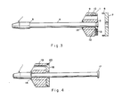
- Figure 3 shows the projectile with its stabilizing portion positioned at its tail and with the sabot obturating disc shown detached,
- Figure 4 is a side elevation of a sub-caliber projectile having a modified form of sabot means.
- As seen in Figs. 1 through 4 of the drawings the sub-caliber projectile is of the penetrator kind where its length to diameter ratio is significantly high. The projectile is formed with an ogival front end 1, a tail end 2 formed with an annular
peripheral recess 3 and a cylindrically shaped mid-section 4 of substantially-uniform diameter. The latter merges with the ogival front end 1 via an annular,abutment shoulder 5. - The projectile is provided with sabot means 6, comprising an annular obturating disc 7 having a
peripheral skirt 8 and a substantially cylindrical stabilizingmember 9. The latter is formed with a plurality of throughgoing axially directedbores 10 and with aperipheral recess 11 into which is designed to fit theskirt 8. There is furthermore formed in the member 9 a radially directedbore 12 in which is located a spring loaded retainingpin 13. One end of thepin 13 is, as shown in Fig. 1 of the drawings spring biased into a locating bore formed in theskirt 8 and the other end bears against the mid-section 4. - The forward end of the stabilizing member is tapered and is provided at its central planar end portion with a
bearing disc 14. - The sabot means 6 is clearly slidable along the mid-section 4 from a first position, wherein the
bearing disc 14 bears against theabutment shoulder 5, to a second position wherein the innermost end of the spring loadedpin 13 enters therecess 3 thereby allowing for the detachment of the obturating disc 7 (as seen in Fig. 3 of the drawings). The sabot means 6 is also rotationally displaceable with respect to the mid-section 4. - In use with the projectile located in the bore of the launching weapon, the obturating disc 7 supported and located by the stabilizing member9 effectively seals the bore and, upon firing, takes up the propulsion forces and as a consequence the projectile is launched with substantial initial velocity. After launching, the sabot means is displaced rearwardly along the
cylindrical section 4 until theretaining pin 13 enters therecess 3 whereupon the obturating disc 7 is detached and is displaced rearwardly away from the projectile. The stabilizingportion 9 is retained in position at the tail end of the projectile and now performs a conventional function as a stabilizing tail. - In an alternative embodiment of a sabot means, as shown in Fig. 4 of the drawings, the tail end of the projectile is formed with an outwardly directed
flange 17 whilst an annular obturatingdisc 18 is formed with its central aperture of greater diameter than that of theflange 17 and is located in an annular end recess formed in a stabilizingmember 19 otherwise of similar construction to the stabilizing member shown in Fig. 1 of the drawings. In this case, however, the obturatingdisc 18 is secured to the stabilizingmember 19 by means ofshearable retaining pins 20. In the case of this embodiment, upon the rearward displacement of the sabot means after firing towards theflange 17 and upon abutment of this flange by means of the stabilizingmember 19, the momentum acquired by the obturatingdisc 18 together with the stagnation air pressure on the disc, are such as to result in the shearing of the retainingpins 20 and the consequent detachment of thedisc 18 from the stabilizingmember 19 which is retained in position against theflange 17. - It can thus be seen that the incorporation of the stabilizing member in the sabot means and the retention thereof after firing in the correct position on the tail results in a considerable saving of weight. Furthermore, the fact that the detached obturating disc of the sabot means separates from the projectile in a rearward direction minimizes disturbance of the flight of the projectile as a result of the separation. Finally, the fact that the sabot means is rotationally displaceable with respect to the projectile ensures that any spin imparted to the sabot means is not necessarily transmitted to the projectile.
- Whilst the invention has been specifically described with respect to a stabilizing portion of substantially cylindrical shape, it is equally applicable when the stabilizing portion has other forms such as, for example, is formed with radially directed stabilizing fins.
Claims (4)
Applications Claiming Priority (2)
| Application Number | Priority Date | Filing Date | Title |
|---|---|---|---|
| IL65929 | 1982-06-01 | ||
| IL65929A IL65929A0 (en) | 1982-06-01 | 1982-06-01 | Sub-caliber projectile |
Publications (3)
| Publication Number | Publication Date |
|---|---|
| EP0095868A2 EP0095868A2 (en) | 1983-12-07 |
| EP0095868A3 EP0095868A3 (en) | 1984-11-14 |
| EP0095868B1 true EP0095868B1 (en) | 1987-04-01 |
Family
ID=11053533
Family Applications (1)
| Application Number | Title | Priority Date | Filing Date |
|---|---|---|---|
| EP83302867A Expired EP0095868B1 (en) | 1982-06-01 | 1983-05-19 | A sub-caliber projectile |
Country Status (4)
| Country | Link |
|---|---|
| US (1) | US4519317A (en) |
| EP (1) | EP0095868B1 (en) |
| DE (1) | DE3370683D1 (en) |
| IL (1) | IL65929A0 (en) |
Families Citing this family (11)
| Publication number | Priority date | Publication date | Assignee | Title |
|---|---|---|---|---|
| DE3439256C1 (en) * | 1984-10-26 | 1986-01-09 | Messerschmitt-Bölkow-Blohm GmbH, 8012 Ottobrunn | Device for the correction of flight attitude of munitions |
| DE3508053A1 (en) * | 1985-03-07 | 1986-09-18 | Rheinmetall GmbH, 4000 Düsseldorf | BULLET STOCK |
| IL75408A (en) * | 1985-06-05 | 1992-02-16 | Israel State | Sub-caliber projectile |
| DE3833001A1 (en) * | 1988-09-29 | 1990-04-05 | Mauser Werke Oberndorf | SUB-CALIBRAL AMMUNITION |
| DE4023220C2 (en) * | 1990-07-21 | 1995-02-09 | Rheinmetall Gmbh | Balancing projectile |
| FR2695717B1 (en) * | 1992-09-16 | 1994-11-25 | Saint Louis Inst | Shoe for accelerator projectile by ramjet effect and projectile equipped with such a shoe. |
| NO995141A (en) * | 1999-06-04 | 2000-10-16 | Nammo Raufoss As | Missile feed and locking mechanism |
| RU2194943C2 (en) * | 2000-04-28 | 2002-12-20 | Научно-исследовательский институт прикладной математики и механики | Hard-core projectile |
| US20070234925A1 (en) * | 2004-09-07 | 2007-10-11 | Dunn Robert H | Sabot allowing .17-caliber projectile use in a .22-caliber weapon |
| DE102008029397A1 (en) | 2008-06-23 | 2009-12-24 | Rheinmetall Waffe Munition Gmbh | Sabot projectile |
| US10502515B2 (en) * | 2017-01-17 | 2019-12-10 | Raytheon Company | Launch piston brake |
Family Cites Families (12)
| Publication number | Priority date | Publication date | Assignee | Title |
|---|---|---|---|---|
| US3125957A (en) * | 1964-03-24 | lipinski | ||
| US3125956A (en) * | 1964-03-24 | Fold able fin | ||
| US2045833A (en) * | 1935-05-01 | 1936-06-30 | Bliss G Childs | Bullet |
| US2306140A (en) * | 1940-09-27 | 1942-12-22 | George E Dieckman | Projectile and bullet |
| GB662430A (en) * | 1945-03-09 | 1951-12-05 | Latham Valentine Stewart Black | Improvements relating to projectiles |
| FR1206606A (en) * | 1951-11-07 | 1960-02-10 | Tech De Rech S Ind & Mecanique | Fletched projectile |
| US2752850A (en) * | 1952-01-30 | 1956-07-03 | Arthur H Warner | Self-propelled missile |
| US2773450A (en) * | 1953-04-18 | 1956-12-11 | Soltam Ltd | Mortar projectile |
| US4024998A (en) * | 1956-03-07 | 1977-05-24 | The United States Of America As Represented By The Secretary Of The Army | Rocket |
| IL37041A (en) * | 1971-06-14 | 1976-02-29 | State Of Il Ministry Of Def | Forward sabot for sub-calibre projectile with delayed detachment |
| US3961580A (en) * | 1975-02-27 | 1976-06-08 | The United States Of America As Represented By The Secretary Of The Navy | Energy-absorbing sabot |
| NL7708254A (en) * | 1977-07-25 | 1979-01-29 | Eurometaal Nv | EXERCISE PROJECTILE. |
-
1982
- 1982-06-01 IL IL65929A patent/IL65929A0/en not_active IP Right Cessation
-
1983
- 1983-05-19 EP EP83302867A patent/EP0095868B1/en not_active Expired
- 1983-05-19 DE DE8383302867T patent/DE3370683D1/en not_active Expired
- 1983-05-31 US US06/501,069 patent/US4519317A/en not_active Expired - Fee Related
Also Published As
| Publication number | Publication date |
|---|---|
| DE3370683D1 (en) | 1987-05-07 |
| US4519317A (en) | 1985-05-28 |
| EP0095868A2 (en) | 1983-12-07 |
| EP0095868A3 (en) | 1984-11-14 |
| IL65929A0 (en) | 1984-04-30 |
Similar Documents
| Publication | Publication Date | Title |
|---|---|---|
| US4187783A (en) | Discarding sabot munition | |
| EP0255214B1 (en) | Multiple flechette warhead | |
| US5339743A (en) | Ammunition system comprising slug holding sabot and slug type shot shell | |
| US5515787A (en) | Tubular projectile | |
| US3738279A (en) | Sabot for sub-calibre projectile | |
| US3762332A (en) | Projectile sabot | |
| US4140061A (en) | Short-range discarding-sabot training practice round and self-destruct subprojectile therefor | |
| US3714900A (en) | Discarding sabot projectiles | |
| US3771458A (en) | Sabot projectile | |
| US4802415A (en) | Telescoped ammunition round having subcaliber projectile sabot with integral piston | |
| US3726231A (en) | Sabot bullet | |
| US4029018A (en) | Sabot for subcalibre projectile | |
| US4362107A (en) | Practice projectile | |
| US4408538A (en) | Launching mechanism for subcalibre projectile | |
| US3905299A (en) | Discarding sabot projectiles | |
| US4800816A (en) | Delay discarding sabot projectile | |
| US5297492A (en) | Armor piercing fin-stabilized discarding sabot tracer projectile | |
| US4590862A (en) | Projectile pusher-type discarding sabot | |
| US3769912A (en) | Spin-stabilized projectiles | |
| US5196650A (en) | Projectile and sabot assembly | |
| US4519317A (en) | Sub-caliber projectile | |
| US3177809A (en) | Semi-fixed artillery round | |
| US3862603A (en) | Light weight sabot | |
| US4382411A (en) | Self aligning expansible sabot projectile for worn gun tubes | |
| US4939997A (en) | Article of ammunition |
Legal Events
| Date | Code | Title | Description |
|---|---|---|---|
| PUAI | Public reference made under article 153(3) epc to a published international application that has entered the european phase |
Free format text: ORIGINAL CODE: 0009012 |
|
| AK | Designated contracting states |
Designated state(s): DE FR GB IT |
|
| PUAL | Search report despatched |
Free format text: ORIGINAL CODE: 0009013 |
|
| AK | Designated contracting states |
Designated state(s): DE FR GB IT |
|
| RAP1 | Party data changed (applicant data changed or rights of an application transferred) |
Owner name: THE STATE OF ISRAEL MINISTRY OF DEFENCE RAFAEL - |
|
| RAP1 | Party data changed (applicant data changed or rights of an application transferred) |
Owner name: THE STATE OF ISRAEL MINISTRY OF DEFENCE RAFAEL - |
|
| 17P | Request for examination filed |
Effective date: 19850423 |
|
| 17Q | First examination report despatched |
Effective date: 19860211 |
|
| GRAA | (expected) grant |
Free format text: ORIGINAL CODE: 0009210 |
|
| AK | Designated contracting states |
Kind code of ref document: B1 Designated state(s): DE FR GB IT |
|
| REF | Corresponds to: |
Ref document number: 3370683 Country of ref document: DE Date of ref document: 19870507 |
|
| ITF | It: translation for a ep patent filed | ||
| ET | Fr: translation filed | ||
| PLBE | No opposition filed within time limit |
Free format text: ORIGINAL CODE: 0009261 |
|
| STAA | Information on the status of an ep patent application or granted ep patent |
Free format text: STATUS: NO OPPOSITION FILED WITHIN TIME LIMIT |
|
| 26N | No opposition filed | ||
| ITTA | It: last paid annual fee | ||
| PGFP | Annual fee paid to national office [announced via postgrant information from national office to epo] |
Ref country code: FR Payment date: 19930305 Year of fee payment: 11 |
|
| PGFP | Annual fee paid to national office [announced via postgrant information from national office to epo] |
Ref country code: DE Payment date: 19930408 Year of fee payment: 11 |
|
| PGFP | Annual fee paid to national office [announced via postgrant information from national office to epo] |
Ref country code: GB Payment date: 19930512 Year of fee payment: 11 |
|
| PG25 | Lapsed in a contracting state [announced via postgrant information from national office to epo] |
Ref country code: GB Effective date: 19940519 |
|
| GBPC | Gb: european patent ceased through non-payment of renewal fee |
Effective date: 19940519 |
|
| PG25 | Lapsed in a contracting state [announced via postgrant information from national office to epo] |
Ref country code: FR Effective date: 19950131 |
|
| PG25 | Lapsed in a contracting state [announced via postgrant information from national office to epo] |
Ref country code: DE Effective date: 19950201 |
|
| REG | Reference to a national code |
Ref country code: FR Ref legal event code: ST |