EP0095854A2 - Elektrolytische Reduktionszellen für die Aluminiumproduktion - Google Patents
Elektrolytische Reduktionszellen für die Aluminiumproduktion Download PDFInfo
- Publication number
- EP0095854A2 EP0095854A2 EP83302801A EP83302801A EP0095854A2 EP 0095854 A2 EP0095854 A2 EP 0095854A2 EP 83302801 A EP83302801 A EP 83302801A EP 83302801 A EP83302801 A EP 83302801A EP 0095854 A2 EP0095854 A2 EP 0095854A2
- Authority
- EP
- European Patent Office
- Prior art keywords
- cell
- electrolyte
- cathode
- side walls
- tiles
- Prior art date
- Legal status (The legal status is an assumption and is not a legal conclusion. Google has not performed a legal analysis and makes no representation as to the accuracy of the status listed.)
- Granted
Links
Images
Classifications
-
- C—CHEMISTRY; METALLURGY
- C25—ELECTROLYTIC OR ELECTROPHORETIC PROCESSES; APPARATUS THEREFOR
- C25C—PROCESSES FOR THE ELECTROLYTIC PRODUCTION, RECOVERY OR REFINING OF METALS; APPARATUS THEREFOR
- C25C3/00—Electrolytic production, recovery or refining of metals by electrolysis of melts
- C25C3/06—Electrolytic production, recovery or refining of metals by electrolysis of melts of aluminium
- C25C3/16—Electric current supply devices, e.g. bus bars
-
- C—CHEMISTRY; METALLURGY
- C25—ELECTROLYTIC OR ELECTROPHORETIC PROCESSES; APPARATUS THEREFOR
- C25C—PROCESSES FOR THE ELECTROLYTIC PRODUCTION, RECOVERY OR REFINING OF METALS; APPARATUS THEREFOR
- C25C3/00—Electrolytic production, recovery or refining of metals by electrolysis of melts
- C25C3/06—Electrolytic production, recovery or refining of metals by electrolysis of melts of aluminium
- C25C3/08—Cell construction, e.g. bottoms, walls, cathodes
Definitions
- the present invention relates to electrolytic reduction cells and in particular to electrolytic reduction cells for the production of aluminium by the reduction of alumina in a molten fluoride salt bath.
- the electrolyte is contained in a cell, lined with carbon blocks.
- the floor of the cell is covered by a layer of molten aluminium metal, which constitutes the cathode of the cell, and the cathode current is conducted downward through the floor of the cell to collector bars embedded in the carbon floor blocks and connected to bus bars, which normally extend lengthwise on opposite sides of the cell.
- the solidified electrolyte is relatively non-conductive and so insulates the side walls of the cell from the cell currents.
- the bottom and sometimes the side walls of the cell are thermally insulated.
- the cell bottom is usually so heavily insulated that the heat loss through the bottom is probably as small as 5% of the total heat loss from the cell and consequently there is little possibility of further reduction of the heat loss in that.direction.
- one route presenting an opportunity of achieving a significant reduction in heat loss is to improve the insulation of the side walls. This involves either increase of the thickness of the insulation or employing an insulation of superior properties.
- a reduction of the heat loss through the side walls has the effect of an increase in temperature at the wall/electrolyte interface and eventually the elimination of the protective layer of solidified electrolyte.
- the disappearance of the solidified electrolyte has a twofold disadvantage in that (a) it exposes the carbon lining to erosion by molten electrolyte (b) it establishes a current leakage path for the cathode current with attendant loss in efficiency.
- the heat loss from the cell through the portion of the cell wall in contact with the electrolyte is such that the formation of a solidified electrolyte layer at the cell wall will not take place so long as the electrolyte is maintained at an ordinary temperature of about 960°C.
- the flow of current from the anodes to cathodically connected walls is particularly undesirable because the essentially horizontal currents react with the electromagnetic fields associated with the carriers of the electrical currents (cathode collector bars, bus bars etc.) and thus lead to magnetohydrodynamic disturbances in the electrolyte.
- an electrolytic reduction cell for the production of aluminium having a floor and side walls constructed of material resistant to attack by molten aluminium, the side walls being lined at least in part with ceramic material resistant to attack by the cell electrolyte and by molten aluminium, and being provided with thermal insulation to an extent such that a layer of solidified electrolyte is not present thereon during normal operation of the cell, the cell having a cathode -current collection system arranged in such a manner that the horizontal lateral currents in the cathode are insignificant compared with the vertical current.
- the preferred ceramic materials are borides nitrides, oxynitrides etc., one suitable material being titanium diboride, either as fabricated bodies or as coatings on other materials such as alumina, silicon carbide etc.
- Such ceramic materials are extremely resistant to attack by the fluoride electrolyte and the metal of the reduction cell. They may however also be both thermally and electrically conductive and in such cases must be considered in terms of possessing metal- like characteristics rather than in terms of ceramics, which are normally both thermal and electrical insulators.
- electrolyte-resistant borides are coated onto silicon carbide, the composite material is of advantageously low thermal and electrical conductivity.
- the cathode structure should be arranged so that the proportion of the cathode current entering through the side walls is very small indeed.
- the horizontal lateral currents in the cell in a molten metal pad and/or in a conductive floor
- the cathode current collectors are straight rods in electrical contact with the carbon floor blocks.
- the cell has a carbon floor which constitutes the cathode and the cathode current collection system comprises a plurality of current collector bars located in unitary form or in separate sections in the underside of the cell floor, there being provided a plurality of connector bars for each collector bar and each connector bar being connected at a point intermediate the ends of the collector bar or collector bar section.
- silicon carbide particles proposed by the patent are substantially less resistant to attack by molten electrolyte and molten aluminium than are the diboride ceramics employed in the present invention. Any silicon carbide particles, displaced from the side wall by attack of the carbon matrix by the electrolyte, will form a constant source of silicon for attack by the product metal. That would result in silicon contamination of such metal and its downgrading as a commercial product.
- the patent does not address the further problems which arise when an electrically conductive ceramic material is used to line the side walls.
- the cell illustrated having a cell wall of steel coated with titanium diboride, has cathode current collectors connected directly to the floor of the pot. Iri the case of cells formed of carbon, the patent teaches that the cathode current collectors would be embedded in the vessel wall in the conventional manner. Such an arrangement, with electrically conducting side walls and no protective layer of solidified electrolyte, would,give rise to unacceptably large horizontal lateral currents, which could disturb the layers of electrolyte and metal in the cell.
- the walls and floor of the cell are constructed of material resistant to attack by molten aluminium; and the cell walls are preferably formed of separate titanium diboride or equivalent tiles or panels.
- These may be embedded in a conventional carbon material, so that local failure of the ceramic cannot lead to disastrous failure of the cell.
- they may be embedded in alumina or welded to a composite ceramic base material comprising Group IVb, Vb or VIb refractory metal carbides, borides or nitrides with an Al-containing phase such as alumina.
- the bottom edges of the ceramic tiles are fixed for structural stability, but they are free to expand or contract in the vertical direction without undue stress being developed.
- Conventional carbon cathode materials are subject to expansion when exposed to molten cryolite due to sodium pick-up. Where the bottoms of the ceramic tiles are embedded in conventional carbon materials, differential expansion may cause the tiles to crack.
- Graphitized carbon materials are much less subject to attack by cryolite and are preferable to ordinary carbon.
- the highly insulated side wall system of the present invention is very conveniently employed in conjunction with any system for damping out or preventing movement or distortion of the pool of molten metal in the bottom of the cell with the consequent possibility of reduction of the anode-cathode distance of the cell.
- the floor of the cell may in some instances also be lined with TiB 2 ceramic tiles, although in may cases a conventional carbon floor will be satisfactory, provided that an appropriate current collection system is provided.
- the thickness of the ceramic tiles of the cell side walls would usually be not less than 0.25 cm, preferably at least 0.5 cm, by contrast with the sprayed-on layer of ceramic particles having a thickness about 0.5 mm, described in United States Patent No. 3,856,650.
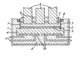
- the accompanying drawing is a sectional side elevation of an electrolytic reduction cell according to the invention.
- a thermally and electrically insulating lining 2 of alumina blocks Within a steel shell 1 is a thermally and electrically insulating lining 2 of alumina blocks.
- the cathode of the cell is constituted by a pad 3 of molten aluminium supported on a bed 4 of carbon blocks. Overlying the molten metal pad 3 is a layer 5 of molten electrolyte, in which anodes 6 are suspended.
- Ceramic tiles 7 constitute the side walls of the cell. These are fixed at their lower edges in slots machined in the carbon blocks 4, their upper edges being free. Behind each tile 7 adjacent its upper edge there is a pipe 8 for coolant. A solid crust 9 has formed on the top of the electrolyte layer 5. Because of the cooling pipe 8, this crust surrounds the top edges of the tiles 7 and protects them from atmospheric attack.
- a current collector bar 10 is shown in four sections between the carbon bed 4 and the alumina lining 2. Each section is connected at a point intermediate its ends to a connector bats 11 which extends through the shell 1. The electrical power supply between the anodes 6 and the connector bars 11 outside the cell are not shown.
- the electrolyte 5 is maintained at a temperature of around 960°C.
- the thermal insulation 2 behind the ceramic tiles 7 is so-good that a layer of frozen electrolyte does not form on the tiles, except at their upper edges.
- the current collection system 10, 11 ensures that the current passes substantially vertically through the carbon bed 4. Only an insignificant fraction of the current appears at the side walls. No significant amount of current flows from the anodes 6 to the side walls 7.
Landscapes
- Chemical & Material Sciences (AREA)
- Engineering & Computer Science (AREA)
- Chemical Kinetics & Catalysis (AREA)
- Electrochemistry (AREA)
- Materials Engineering (AREA)
- Metallurgy (AREA)
- Organic Chemistry (AREA)
- Electrolytic Production Of Metals (AREA)
- Secondary Cells (AREA)
Applications Claiming Priority (2)
| Application Number | Priority Date | Filing Date | Title |
|---|---|---|---|
| GB8215728 | 1982-05-28 | ||
| GB8215728 | 1982-05-28 |
Publications (3)
| Publication Number | Publication Date |
|---|---|
| EP0095854A2 true EP0095854A2 (de) | 1983-12-07 |
| EP0095854A3 EP0095854A3 (en) | 1984-04-25 |
| EP0095854B1 EP0095854B1 (de) | 1987-08-19 |
Family
ID=10530720
Family Applications (1)
| Application Number | Title | Priority Date | Filing Date |
|---|---|---|---|
| EP83302801A Expired EP0095854B1 (de) | 1982-05-28 | 1983-05-17 | Elektrolytische Reduktionszellen für die Aluminiumproduktion |
Country Status (8)
| Country | Link |
|---|---|
| US (1) | US4592820A (de) |
| EP (1) | EP0095854B1 (de) |
| JP (1) | JPS58213888A (de) |
| AU (1) | AU561730B2 (de) |
| CA (1) | CA1216254A (de) |
| DE (1) | DE3373115D1 (de) |
| ES (1) | ES522773A0 (de) |
| NO (1) | NO163870C (de) |
Cited By (5)
| Publication number | Priority date | Publication date | Assignee | Title |
|---|---|---|---|---|
| EP0308014A1 (de) * | 1987-09-16 | 1989-03-22 | MOLTECH Invent S.A. | Feuerfeste Oxidverbindung/feuerfester Hartmetallverbundwerkstoff |
| WO1992003598A1 (en) * | 1990-08-20 | 1992-03-05 | Comalco Aluminium Limited | Ledge-free aluminium smelting cell |
| AU639367B2 (en) * | 1990-08-20 | 1993-07-22 | Comalco Aluminium Limited | Ledge-free aluminium smelting cell |
| WO1996037637A1 (en) * | 1995-05-26 | 1996-11-28 | Saint-Gobain Industrial Ceramics, Inc. | Lining for aluminum production furnace |
| WO2012039624A1 (en) * | 2010-09-22 | 2012-03-29 | Goodtech Recovery Technology As | System and method for control of side layer formation in an aluminium electrolysis cell |
Families Citing this family (18)
| Publication number | Priority date | Publication date | Assignee | Title |
|---|---|---|---|---|
| GB8522138D0 (en) * | 1985-09-06 | 1985-10-09 | Alcan Int Ltd | Linings for aluminium reduction cells |
| WO1989002490A1 (en) * | 1987-09-16 | 1989-03-23 | Eltech Systems Corporation | Composite cell bottom for aluminum electrowinning |
| US5667664A (en) * | 1990-08-20 | 1997-09-16 | Comalco Aluminum Limited | Ledge-free aluminum smelting cell |
| US6001236A (en) * | 1992-04-01 | 1999-12-14 | Moltech Invent S.A. | Application of refractory borides to protect carbon-containing components of aluminium production cells |
| US5651874A (en) * | 1993-05-28 | 1997-07-29 | Moltech Invent S.A. | Method for production of aluminum utilizing protected carbon-containing components |
| EP0633870B1 (de) * | 1992-04-01 | 1999-11-24 | MOLTECH Invent S.A. | Verhinderung der oxydation von kohlenstoffhaltigem material bei hohen temperaturen |
| US5310476A (en) * | 1992-04-01 | 1994-05-10 | Moltech Invent S.A. | Application of refractory protective coatings, particularly on the surface of electrolytic cell components |
| WO1996007773A1 (en) * | 1994-09-08 | 1996-03-14 | Moltech Invent S.A. | Aluminium electrowinning cell with improved carbon cathode blocks |
| US5753163A (en) * | 1995-08-28 | 1998-05-19 | Moltech. Invent S.A. | Production of bodies of refractory borides |
| US6258246B1 (en) * | 1998-05-19 | 2001-07-10 | Moltech Invent S.A. | Aluminium electrowinning cell with sidewalls resistant to molten electrolyte |
| NO313462B1 (no) | 2000-06-07 | 2002-10-07 | Elkem Materials | Elektrolysecelle for fremstilling av aluminium, en rekke elektrolyseceller i en elektrolysehall, fremgangsmåte for åopprettholde en kruste på en sidevegg i en elektrolysecelle samtfremgangsmåte for gjenvinning av elektrisk energi fra en elektr |
| US6863788B2 (en) * | 2002-07-29 | 2005-03-08 | Alcoa Inc. | Interlocking wettable ceramic tiles |
| WO2006053372A1 (en) * | 2004-10-21 | 2006-05-26 | Bhp Billiton Innovation Pty Ltd | Internal cooling of electrolytic smelting cell |
| FR2882051B1 (fr) * | 2005-02-17 | 2007-04-20 | Saint Gobain Ct Recherches | Bloc refractaire fritte composite pour cuve d'electrolyse de l'aluminium et procede de fabrication de ce bloc |
| FR2893329B1 (fr) * | 2005-11-14 | 2008-05-16 | Aluminium Pechiney Soc Par Act | Cuve d'electrolyse avec echangeur thermique. |
| NO332480B1 (no) * | 2006-09-14 | 2012-09-24 | Norsk Hydro As | Elektrolysecelle samt fremgangsmate for drift av samme |
| EP2766516B1 (de) * | 2011-10-10 | 2016-11-16 | Goodtech Recovery Technology AS | System und verfahren zur steuerung der schichtbildung in einer aluminiumelektrolysezelle |
| WO2014091023A1 (de) * | 2012-12-13 | 2014-06-19 | Sgl Carbon Se | Seitenstein für eine wand in einer elektrolysezelle zur reduzierung von aluminum |
Family Cites Families (17)
| Publication number | Priority date | Publication date | Assignee | Title |
|---|---|---|---|---|
| US3151053A (en) * | 1958-06-12 | 1964-09-29 | Kaiser Aluminium Chem Corp | Metallurgy |
| FR1229537A (fr) * | 1959-07-10 | 1960-09-07 | British Aluminium Co Ltd | Perfectionnements aux cuves électrolytiques pour la production de l'aluminium |
| US3093570A (en) * | 1959-10-20 | 1963-06-11 | Reynolds Metals Co | Refractory lining for alumina reduction cells |
| DE1146259B (de) * | 1960-10-28 | 1963-03-28 | Aluminium Ind Ag | Verfahren zum Auskleiden der Waende der Kathodenwanne einer Aluminium-elektrolysezelle und nach diesem Verfahren hergestellte Kathodenwanne |
| DE1251962B (de) * | 1963-11-21 | 1967-10-12 | The British Aluminium Company Limited, London | Kathode fur eine Elektrolysezelle zur Herstellung von Aluminium und Verfahren zur Herstellung derselben |
| CH576005A5 (de) * | 1972-03-21 | 1976-05-31 | Alusuisse | |
| US3779699A (en) * | 1973-03-15 | 1973-12-18 | Aluminum Co Of America | Furnace structure |
| US4071420A (en) * | 1975-12-31 | 1978-01-31 | Aluminum Company Of America | Electrolytic production of metal |
| JPS5332811A (en) * | 1976-09-07 | 1978-03-28 | Mitsubishi Keikinzoku Kogyo | Reduction of heat radiation in the aluminium electrolytic cell |
| US4093524A (en) * | 1976-12-10 | 1978-06-06 | Kaiser Aluminum & Chemical Corporation | Bonding of refractory hard metal |
| GB2008617B (en) * | 1977-11-23 | 1982-03-31 | Alcan Res & Dev | Electrolytic reduction cells |
| US4194959A (en) * | 1977-11-23 | 1980-03-25 | Alcan Research And Development Limited | Electrolytic reduction cells |
| JPS55125289A (en) * | 1979-03-16 | 1980-09-26 | Sumitomo Alum Smelt Co Ltd | Cathode furnace bottom for aluminum electrolytic furnace |
| UST993002I4 (en) * | 1979-05-29 | 1980-04-01 | Reynolds Metals Company | Refractory surfaces for alumina reduction cell cathodes and methods for providing such surfaces |
| US4224128A (en) * | 1979-08-17 | 1980-09-23 | Ppg Industries, Inc. | Cathode assembly for electrolytic aluminum reduction cell |
| US4396482A (en) * | 1980-07-21 | 1983-08-02 | Aluminum Company Of America | Composite cathode |
| US4405433A (en) * | 1981-04-06 | 1983-09-20 | Kaiser Aluminum & Chemical Corporation | Aluminum reduction cell electrode |
-
1983
- 1983-05-17 EP EP83302801A patent/EP0095854B1/de not_active Expired
- 1983-05-17 DE DE8383302801T patent/DE3373115D1/de not_active Expired
- 1983-05-24 CA CA000428683A patent/CA1216254A/en not_active Expired
- 1983-05-26 JP JP58093326A patent/JPS58213888A/ja active Granted
- 1983-05-27 ES ES522773A patent/ES522773A0/es active Granted
- 1983-05-27 AU AU15099/83A patent/AU561730B2/en not_active Ceased
- 1983-05-27 NO NO831915A patent/NO163870C/no unknown
-
1985
- 1985-09-12 US US06/775,735 patent/US4592820A/en not_active Expired - Fee Related
Cited By (12)
| Publication number | Priority date | Publication date | Assignee | Title |
|---|---|---|---|---|
| EP0308014A1 (de) * | 1987-09-16 | 1989-03-22 | MOLTECH Invent S.A. | Feuerfeste Oxidverbindung/feuerfester Hartmetallverbundwerkstoff |
| WO1989002423A1 (en) * | 1987-09-16 | 1989-03-23 | Moltech Invent S.A. | Refractory oxycompound/refractory hard metal composite |
| WO1989002488A1 (en) * | 1987-09-16 | 1989-03-23 | Eltech Systems Corporation | Refractory oxycompound/refractory hard metal composite |
| US5004524A (en) * | 1987-09-16 | 1991-04-02 | Moltech Invent S.A. | Refractory oxycompound/refractory hard metal composite and used in molten salt aluminum production cells |
| AU617129B2 (en) * | 1987-09-16 | 1991-11-21 | Moltech Invent S.A. | Refractory oxycompound/refractory hard metal composite |
| WO1992003598A1 (en) * | 1990-08-20 | 1992-03-05 | Comalco Aluminium Limited | Ledge-free aluminium smelting cell |
| AU639367B2 (en) * | 1990-08-20 | 1993-07-22 | Comalco Aluminium Limited | Ledge-free aluminium smelting cell |
| WO1996037637A1 (en) * | 1995-05-26 | 1996-11-28 | Saint-Gobain Industrial Ceramics, Inc. | Lining for aluminum production furnace |
| AU698926B2 (en) * | 1995-05-26 | 1998-11-12 | Saint-Gobain Industrial Ceramics, Inc. | Improved lining for aluminum production furnace |
| CN1078267C (zh) * | 1995-05-26 | 2002-01-23 | 圣戈本陶瓷及塑料股份有限公司 | 用于电解还原氧化铝的霍尔槽及其侧壁 |
| WO2012039624A1 (en) * | 2010-09-22 | 2012-03-29 | Goodtech Recovery Technology As | System and method for control of side layer formation in an aluminium electrolysis cell |
| EP2619518A4 (de) * | 2010-09-22 | 2017-05-17 | Goodtech Recovery Technology AS | System und verfahren zur steuerung der seitenschichtbildung in einer aluminiumelektrolysezelle |
Also Published As
| Publication number | Publication date |
|---|---|
| AU1509983A (en) | 1983-12-01 |
| NO831915L (no) | 1983-11-29 |
| AU561730B2 (en) | 1987-05-14 |
| ES8404423A1 (es) | 1984-04-16 |
| NO163870C (no) | 1990-08-01 |
| JPH0243832B2 (de) | 1990-10-01 |
| US4592820A (en) | 1986-06-03 |
| CA1216254A (en) | 1987-01-06 |
| ES522773A0 (es) | 1984-04-16 |
| DE3373115D1 (en) | 1987-09-24 |
| EP0095854B1 (de) | 1987-08-19 |
| EP0095854A3 (en) | 1984-04-25 |
| JPS58213888A (ja) | 1983-12-12 |
| NO163870B (no) | 1990-04-23 |
Similar Documents
| Publication | Publication Date | Title |
|---|---|---|
| US4592820A (en) | Electrolytic reduction cells for aluminium production | |
| US4596637A (en) | Apparatus and method for electrolysis and float | |
| US4622111A (en) | Apparatus and method for electrolysis and inclined electrodes | |
| US4376690A (en) | Cathode for a cell for fused salt electrolysis | |
| US5560809A (en) | Improved lining for aluminum production furnace | |
| US4405433A (en) | Aluminum reduction cell electrode | |
| US4093524A (en) | Bonding of refractory hard metal | |
| US6402928B1 (en) | Aluminium production cell with an insulating cover having individually removable sections | |
| US4532017A (en) | Floating cathode elements based on electrically conductive refractory material, for the production of aluminum by electrolysis | |
| US4664760A (en) | Electrolytic cell and method of electrolysis using supported electrodes | |
| EP0126555A1 (de) | Elektrolytische Zelle und Verfahren | |
| US6558526B2 (en) | Method of converting Hall-Heroult cells to inert anode cells for aluminum production | |
| US4737247A (en) | Inert anode stable cathode assembly | |
| AU2001241757A1 (en) | Method of converting hall-heroult cells to inert anode | |
| US4118304A (en) | Electrolytic alumina reduction cell with heat radiation reducing means | |
| Ransley | Refractory carbides and borides for aluminum reduction cells | |
| GB2136450A (en) | Cell for the refining of aluminium | |
| US3178363A (en) | Apparatus and process for production of aluminum and other metals by fused bath electrolysis | |
| US4383910A (en) | Alumina reduction cell | |
| US3700581A (en) | Cryolitic vat for the production of aluminum by electrolysis | |
| US6551473B1 (en) | Electrolytic cell arrangement for production of aluminum | |
| US4450054A (en) | Alumina reduction cell | |
| US4498966A (en) | Alumina reduction cell | |
| AU615596B2 (en) | Supersaturation plating of aluminum wettable cathode coatings during aluminum smelting in drained cathode cells |
Legal Events
| Date | Code | Title | Description |
|---|---|---|---|
| PUAI | Public reference made under article 153(3) epc to a published international application that has entered the european phase |
Free format text: ORIGINAL CODE: 0009012 |
|
| AK | Designated contracting states |
Designated state(s): CH DE FR GB LI |
|
| RAP1 | Party data changed (applicant data changed or rights of an application transferred) |
Owner name: ALCAN INTERNATIONAL LIMITED |
|
| PUAL | Search report despatched |
Free format text: ORIGINAL CODE: 0009013 |
|
| AK | Designated contracting states |
Designated state(s): CH DE FR GB LI |
|
| 17P | Request for examination filed |
Effective date: 19840511 |
|
| RAP1 | Party data changed (applicant data changed or rights of an application transferred) |
Owner name: ALCAN INTERNATIONAL LIMITED |
|
| GRAA | (expected) grant |
Free format text: ORIGINAL CODE: 0009210 |
|
| AK | Designated contracting states |
Kind code of ref document: B1 Designated state(s): CH DE FR GB LI |
|
| REF | Corresponds to: |
Ref document number: 3373115 Country of ref document: DE Date of ref document: 19870924 |
|
| ET | Fr: translation filed | ||
| PLBE | No opposition filed within time limit |
Free format text: ORIGINAL CODE: 0009261 |
|
| STAA | Information on the status of an ep patent application or granted ep patent |
Free format text: STATUS: NO OPPOSITION FILED WITHIN TIME LIMIT |
|
| 26N | No opposition filed | ||
| PGFP | Annual fee paid to national office [announced via postgrant information from national office to epo] |
Ref country code: CH Payment date: 19900417 Year of fee payment: 8 |
|
| PGFP | Annual fee paid to national office [announced via postgrant information from national office to epo] |
Ref country code: FR Payment date: 19900418 Year of fee payment: 8 |
|
| PGFP | Annual fee paid to national office [announced via postgrant information from national office to epo] |
Ref country code: DE Payment date: 19900420 Year of fee payment: 8 |
|
| PGFP | Annual fee paid to national office [announced via postgrant information from national office to epo] |
Ref country code: GB Payment date: 19900427 Year of fee payment: 8 |
|
| PG25 | Lapsed in a contracting state [announced via postgrant information from national office to epo] |
Ref country code: GB Effective date: 19910517 |
|
| PG25 | Lapsed in a contracting state [announced via postgrant information from national office to epo] |
Ref country code: LI Effective date: 19910531 Ref country code: CH Effective date: 19910531 |
|
| GBPC | Gb: european patent ceased through non-payment of renewal fee | ||
| PG25 | Lapsed in a contracting state [announced via postgrant information from national office to epo] |
Ref country code: FR Effective date: 19920131 |
|
| REG | Reference to a national code |
Ref country code: CH Ref legal event code: PL |
|
| PG25 | Lapsed in a contracting state [announced via postgrant information from national office to epo] |
Ref country code: DE Effective date: 19920303 |
|
| REG | Reference to a national code |
Ref country code: FR Ref legal event code: ST |