EP0094674B1 - Guide with rolling elements - Google Patents
Guide with rolling elements Download PDFInfo
- Publication number
- EP0094674B1 EP0094674B1 EP83104829A EP83104829A EP0094674B1 EP 0094674 B1 EP0094674 B1 EP 0094674B1 EP 83104829 A EP83104829 A EP 83104829A EP 83104829 A EP83104829 A EP 83104829A EP 0094674 B1 EP0094674 B1 EP 0094674B1
- Authority
- EP
- European Patent Office
- Prior art keywords
- balls
- ball
- shoe
- travel
- rows
- Prior art date
- Legal status (The legal status is an assumption and is not a legal conclusion. Google has not performed a legal analysis and makes no representation as to the accuracy of the status listed.)
- Expired
Links
Images

Classifications
-
- F—MECHANICAL ENGINEERING; LIGHTING; HEATING; WEAPONS; BLASTING
- F16—ENGINEERING ELEMENTS AND UNITS; GENERAL MEASURES FOR PRODUCING AND MAINTAINING EFFECTIVE FUNCTIONING OF MACHINES OR INSTALLATIONS; THERMAL INSULATION IN GENERAL
- F16C—SHAFTS; FLEXIBLE SHAFTS; ELEMENTS OR CRANKSHAFT MECHANISMS; ROTARY BODIES OTHER THAN GEARING ELEMENTS; BEARINGS
- F16C29/00—Bearings for parts moving only linearly
- F16C29/04—Ball or roller bearings
- F16C29/06—Ball or roller bearings in which the rolling bodies circulate partly without carrying load
- F16C29/0614—Ball or roller bearings in which the rolling bodies circulate partly without carrying load with a shoe type bearing body, e.g. a body facing one side of the guide rail or track only
- F16C29/0616—Ball or roller bearings in which the rolling bodies circulate partly without carrying load with a shoe type bearing body, e.g. a body facing one side of the guide rail or track only for supporting load essentially in a single direction
Definitions
- the invention relates to a rolling element guide, consisting of a running shoe, which contains several rows in one section under load rotating balls.
- B E uieri for heavy-duty linear bearing, including the machine structural use and, for example, from DE-B-14 25 120 or US-A-34 67 477 are known.
- a separate guide is provided for each row of balls, so that the rows of balls are separated from one another by a certain distance.
- roller roller shoes are also known which have a similar structure to the ball roller shoes mentioned above, but contain rollers instead of the balls.
- Ball circulation shoes have the advantage over roller circulation shoes that no so-called “erasing” occurs, i.e. a sliding, axial offset, which usually does not run exactly parallel to the direction of the rollers in relation to the raceways.
- Recirculating ball guides are, however, less resilient than recirculating roller guides because of the smaller supporting surfaces of the balls with the same dimensions of the shoe.
- roller roller shoes are therefore preferably used.
- roller circulating shoes From DE-C-21 21 847 it is known for roller circulating shoes to design the transition into the load area as a resilient tab which is elastically bent upward by the incoming rollers and thus forms a run-in slope. With this measure, however, an improvement in the running-in behavior is achieved only when the roller circulating shoe is subjected to a greater load, when there is a significant curvature of the flap.
- roller body guide of the type mentioned at the outset, i.e. to design a recirculating ball shoe so that it has the highest possible load capacity in relation to its dimensions.
- wires or threads stretched between the rows of balls for. B. made of nylon. These wires are used for better handling of the bearing during the transpart and during assembly. In the installed state, however, they have no function. Instead of the threads, a thin cover cap made of sheet metal can also be used, which is removed after the bearing has been installed.
- the supporting body of the running shoe consists of a flat plate which is rounded at both ends of the running area and which has its flat bevel in the inlet area or outlet area approximately to the length of a ball diameter owns.
- the angle at which this chamfer is inclined against the running surface of the revolving shoe should correspond approximately to the ratio of the flattening of the balls of the guide occurring at nominal load to the diameter of the balls. This ensures that the pressure on the incoming ball does not increase abruptly, but slowly, or decreases as it runs out.
- the known short-circuit synchronous errors due to the known ball circulation shoes caused by the sudden entry and exit of the balls from the running area are thus avoided.
- the ball circulation shoe shown in FIGS. 1-3 consists of a cuboid housing 1 open at the bottom, in the interior of which a flat support plate 7 is fastened with its narrow side to the two side walls of the housing 1. Between the rounded, front ends of the support plate 7 and the likewise rounded inner sides of the opposite wall of the housing 1 there is a passage for the endlessly rotating balls between the underside of the support plate 7 and the guide (not shown) under load and inside the housing 1 .
- the running area is limited laterally by two strips 8 and 9. Within this running area, the balls of a row are each guided through the two adjacent rows against which they rest.
- the support plate 7 shows the underside 14 of the support plate 7 over a length of approximately one ball diameter in an area 5, which directly adjoins the rounded end face of the support plate 7, between the points denoted by 10 and 1 1 against the barrel t bevelled surface.
- the angle of inclination a of this bevel is so chosen that the incoming ball located at point 15 does not yet experience any Hertzian pressure when the rotating shoe is loaded. On the basis of the characteristic data for common materials, this angle is smaller than 10.
- the support plate 7 also has such a slope S at the opposite end (not shown) in the outlet area of the bearing.
- the graph 13 shows the vertical synchronism error of a ball shoe provided with the slope S again. This process error has a purely long periodic behavior caused by the management.
Description
Die Erfindung betrifft eine Wölzkörperführung, bestehend aus einem Laufschuh, der mehrere Reihen in einem Teilabschnitt unter Last umlaufender Kugeln enthält.The invention relates to a rolling element guide, consisting of a running shoe, which contains several rows in one section under load rotating balls.
Derartige, unter der Bezeichnung "Kugelumlaufschuh" bzw. "Kugelumlaufführung" bekannten BEuelemente finden für hochbelastbare Linearlager, u.a. im Maschinenbau Verwendung und sind beispielsweise aus der DE-B-14 25 120 oder der US-A-34 67 477 bekannt. In den dort beschriebenen Bauelementen ist für jede Reihe Kugeln eine separate Führung vorgesehen, so daß die Kugelreihen durch einen gewissen Abstand voneinander getrennt sind. Aus der DE-C-21 21 847 und der DE-C-22 64 100 sind außerdem Rollenumlaufschuhe bekannt, die einen ähnlichen Aufbau wie die vorstehend genannten Kugelumlaufschuhe besitzen, jedoch anstelle der Kugeln Rollen enthalten.Find such, under the designation "ball bearing unit" or "linear guide system" known B E uelemente for heavy-duty linear bearing, including the machine structural use and, for example, from DE-B-14 25 120 or US-A-34 67 477 are known. In the components described there, a separate guide is provided for each row of balls, so that the rows of balls are separated from one another by a certain distance. From DE-C-21 21 847 and DE-C-22 64 100 roller roller shoes are also known which have a similar structure to the ball roller shoes mentioned above, but contain rollers instead of the balls.
Kugelumlaufschuhe besitzen gegenüber Rollenumlaufschuhen den Vorteil, daß kein sogenanntes "Radieren" auftritt, d.h. ein gleitendes, achsiales Versetzen, der in der Regel nicht exakt parallel zur Führungsrichtung laufenden Rollen gegenüber den Laufbahnen.Ball circulation shoes have the advantage over roller circulation shoes that no so-called "erasing" occurs, i.e. a sliding, axial offset, which usually does not run exactly parallel to the direction of the rollers in relation to the raceways.
Kugelumlaufführungen sind allerdings gegenüber Rollenumlaufführungen geringer belastbar wegen den bei gleichen Abmessungen des Schuhes kleineren tragenden Flächen der Kugeln. Für Anwendungen, bei denen es in erster Linie auf die hahe Belastbarkeit der Wälzkärperführung ankommt, werden daher vorzugsweise Rollenumlaufschuhe eingesetzt.Recirculating ball guides are, however, less resilient than recirculating roller guides because of the smaller supporting surfaces of the balls with the same dimensions of the shoe. For applications in which the high load-bearing capacity of the rolling element guide is of primary importance, roller roller shoes are therefore preferably used.
Sowohl bei Rollenumlaufschuhen als auch bei Kugelumlaufschuhen tritt ein Problem auf, das ihre Verwendung für hachgenaue Aufgabenbereiche, beispielsweise zur Führung verschieblicher Teile in Meß-maschinen, einschränkt. Es besteht darin, daß ein periodischer Ablauffehler in der Gräßenordnung bis zu mehreren 11m auftritt, der durch das Einlaufen einer Kugel oder Rolle vom Umlenkbereich in den Lastbereich und der damit verbundenen Änderung der tragenden Fläche verursacht wird. Dieser Ablauffehler wird noch vergräßert durch das Bestreben der Kugeln in den separat geführten Reihen sich beim Betrieb des Schuhes zu "synchronisieren", d.h. die Kugeln aller Reihen laufen gleichzeitig in den Lastbereich ein bzw. aus.A problem arises both with roller roller shoes and with ball roller shoes, which limits their use for precise tasks, for example for guiding movable parts in measuring machines. It consists in that a periodic sequence error of the order of magnitude up to several 1 1m occurs, which is caused by the entry of a ball or roller from the deflection area into the load area and the associated change in the load-bearing area. This process error is further exacerbated by the efforts of the balls in the separately guided rows to "synchronize" during the operation of the shoe, ie the balls of all rows run into and out of the load area simultaneously.
Aus der DE-C-21 21 847 ist es für Rollenumlaufschuhe bekannt, den Übergang in den Lastbereich als federnden Lappen auszubilden, der von den einlaufenden Rollen elastisch nach oben gebogen wird und damit eine Einlaufschräge bildet. Mit dieser Maßnahme wird jedoch nur bei größerer Belastung des Rollenumlaufschuhes, wenn eine nennenswerte Biegung des Lappens auftritt, eine Verbesserung des Einlaufverhaltens erzielt.From DE-C-21 21 847 it is known for roller circulating shoes to design the transition into the load area as a resilient tab which is elastically bent upward by the incoming rollers and thus forms a run-in slope. With this measure, however, an improvement in the running-in behavior is achieved only when the roller circulating shoe is subjected to a greater load, when there is a significant curvature of the flap.
Aus der DE-C-22 64 100 und der DE-A-26 20 864 ist es bekannt, den Einlaufbereich der Rollen in Rollenumlaufschuhen mit einer f lachen Abschrägung zu versehen. Diese Schräge hat dort jedoch die Aufgabe, den Fluß der Rollen im Einlaufbereich zu verzägern; ihr Anstellwinkel ist dementsprechend groß gewählt. Auch bei diesen bekannten Umlaufschuhen tritt daher der vorstehend genannte Ablauffehler auf.From DE-C-22 64 100 and DE-A-26 20 864 it is known to provide the run-in area of the rollers in roller roller shoes with a flat bevel. However, this slope has the task of delaying the flow of the rollers in the inlet area; their angle of attack is accordingly chosen to be large. The abovementioned process error therefore also occurs in these known revolving shoes.
In der US-A-15 70 056 ist ein Radiallager mit mehreren einander berührenden KJgelreihen bekannt, die zu zwei Gruppen angeordnet sind. Ein Bezug zu den vorstehend genainten Problemen, die bei Linearlagern in Form von Kugelumlaufschuhen auftreten, ist dieser Schrift jedoch nicht zu entnehmen.In US-A-15 70 056 a radial bearing with a plurality of mutually contacting K J is gelreihen known which are arranged into two groups. This document does not, however, provide any reference to the above-mentioned problems which occur with linear bearings in the form of recirculating ball shoes.
Es ist die Aufgabe der vorliegenden Erfindung eine Wälzkärperführung der eingangs genännten Art, d.h. einen Kugelumlaufschuh so auszubilden, daß er bezogen auf seine Abmessungen eine mäglichst hohe Belastbarkeit besitzt.It is the object of the present invention a roller body guide of the type mentioned at the outset, i.e. to design a recirculating ball shoe so that it has the highest possible load capacity in relation to its dimensions.
Diese Aufgabe wird gemäß dem Kennzeichen des Hauptanspruchs dadurch geläst, daß die Kugeln in benachbarten Reihen stets um die Länge eines Kugelradius gegeneinander versetzt und einander berührend angeordnet sind. ,This object is achieved according to the characterizing part of the main claim in that the balls in adjacent rows are always offset from one another by the length of a sphere radius and are arranged in contact with one another. ,
Bei den erfindungsgemäß ausgebildeten Kugelumlaufschuhen wird auf eine separate Führung der Kugelreihen verzichtet. Die Kugeln einzelner Reihen werden vielmehr direkt durch die Kugeln aus benachbarten Reihen geführt, da sie aufgrund der gewählten, dichten Packung nicht ausweichen kännen. Obwohl benachbarte Kugeln daher einander berühren, tritt doch keine nennenswerte Reibung auf, die sich auf den Einsatz der Führung nachteilig auswirken würde.In the recirculating ball shoes designed according to the invention, separate guidance of the rows of balls is dispensed with. The balls of individual rows are rather led directly through the balls from neighboring rows, since they cannot escape due to the selected, dense packing. Although adjacent balls therefore touch each other, there is no significant friction that would have a negative effect on the use of the guide.
Wegen der dichtestmäglichen Packung der tragenden Kugeln ergibt sich bezogen auf die Abmessungen des Schuhes eine hächstmägliche Belastbarkeit und Steifigkeit. Vergleicht man dagegen ein derartiges Lager mit herkämmlichen Kugelumlaufschuhen bei gleicher Belastung, so ergibt sich eine sehr viel hähere Lebensdauer aufgrund des geringeren Druckes pro tragender Kugel. Die gräßere Anzahl der tragenden Kugeln bewirkt außerdem eine bessere Integration der Mikrogeometrie der Lauffläche, was sich positiv auf die Laufruhe des Schuhes auswirkt. Der eingangs erwähnte Effekt der "Synchronisation" wirkt sich nur auf die Hälfte der Kugelreihen aus.Due to the densest-daily packing of the load-bearing balls, the maximum daily resilience and stiffness results in relation to the dimensions of the shoe. If, on the other hand, you compare a bearing of this type with conventional circular ball shoes with the same load, the result is a much longer service life due to the lower pressure per supporting ball. The larger number of supporting balls also results in better integration of the micro-geometry of the tread, which has a positive effect on the running smoothness of the shoe. The "synchronization" effect mentioned at the beginning only affects half of the rows of balls.
Um ein Herausfallen der Kugeln auf der Tragseite des Umlaufschuhes zu verhindern, ist es zweckmäßig, dort zwischen den Kugelreihen gespannte Drähte oder Fäden z. B. aus Nylon anzubringen. Diese Drähte dienen der besseren Handhabung des Lagers beim Transpart und beim Zusammenbau. Im eingebauten Zustand sind sie dagegen ohne Funktian. Anstelle der Fäden kann auch eine dünne Abdeckkappe aus Blech verwendet werden, die nach dem Einbau des Lagers entfernt wird.In order to prevent the balls from falling out on the supporting side of the circulating shoe, it is expedient for wires or threads stretched between the rows of balls, for. B. made of nylon. These wires are used for better handling of the bearing during the transpart and during assembly. In the installed state, however, they have no function. Instead of the threads, a thin cover cap made of sheet metal can also be used, which is removed after the bearing has been installed.
Es ist weiterhin vorteilhaft, wenn der Tragkärper des Laufschuhes aus einer an beiden Enden des Laufbereichs abgerundeten, ebenen Platte besteht, die im Einlaufbereich bzw. Auslaufbereich etwa auf die Länge eines Kugeldurchmesser seine flache Abschrägung besitzt. Der Winkel unter dem diese Abschrägung gegen die Lauffläche des Umlaufschuhes geneigt ist, sollte etwa dem Verhältnis der bei Nennlast auftretenden Abplattung der Kugeln der Führung zum Durchmesser der Kugeln entsprechen. Dadurch ist sichergestellt, daß der Druck auf die einlaufende Kugel nicht abrupt sondern langsäm zunimmt bzw. beim Auslaufen abnimmt. Der bekannten Kugelumlaufschuhen anhafteten, kurzperiodische Gleichlauffehler bedingt durch das plötzliche Eintreten und Austreten der Kugeln aus dem Laufbereich wird somit vermieden.It is also advantageous if the supporting body of the running shoe consists of a flat plate which is rounded at both ends of the running area and which has its flat bevel in the inlet area or outlet area approximately to the length of a ball diameter owns. The angle at which this chamfer is inclined against the running surface of the revolving shoe should correspond approximately to the ratio of the flattening of the balls of the guide occurring at nominal load to the diameter of the balls. This ensures that the pressure on the incoming ball does not increase abruptly, but slowly, or decreases as it runs out. The known short-circuit synchronous errors due to the known ball circulation shoes caused by the sudden entry and exit of the balls from the running area are thus avoided.
Weitere Vorteile der Erfindung sind in der nachfolgenden Beschreibung der Fig. 1-5 der beigefügten Zeichnungen erläutert:
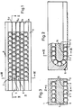
- Fig. 1 zeigt einen Kugelumlaufschuh gemäß der Erfindung in Aufsicht von der Tragseite her gesehen,
- Fig. 2 ist ein Teilschnitt des Schuhes aus Fig. 1 längs der Linie 11-11 in Fig. 1,
- Fig. 3 zeigt einen Schnitt des Schuhes aus Fig. 1 längs der Linie 111-111 in Fig. 1 bzw. Fig. 2,
- Fig. 4 ist eine detailliertere Darstellung des Einlaufbereichs des Schuhes aus Fig. 2,
- Fig. 5 stellt den vertikalen Gleichlauf fehler bekannter Kugelumlauf-5 schuhe (Fig. 5b) und den eines erfindungsgemäßen Kugelumlaufschuhes (Fig. 5a) in Abhängigkeit von seiner Stellung in Führungsrichtung dar.
- 1 shows a recirculating ball shoe according to the invention seen from above on the support side,
- Fig. 2 is a partial section of the shoe of Fig. 1 along the line 11-11 in Fig. 1,
- 3 shows a section of the shoe from FIG. 1 along the line 111-111 in FIG. 1 or FIG. 2,
- 4 is a more detailed illustration of the lead-in area of the shoe of FIG. 2,
- Fig. 5 shows the vertical synchronization errors of known ball circulation shoes (Fig. 5b) and that of a ball circulation shoe according to the invention (Fig. 5a) as a function of its position in the guide direction.
Der in den Fig. 1-3 dargestellte Kugelumlaufschuh besteht aus einem unten offenen, quaderförmigen Gehäuse 1, in dessen Innenraum eine flache Tragplatte 7 mit ihrer Schmalseite an den beiden Seitenwänden des Gehäuses 1 befestigt ist. Zwischen den abgerundeten, stirnseitigen Enden der Tragplatte 7 und den ebenfalls abgerundeten Innenseiten der gegenüberliegenden Wandung des Gehäuses 1 befindet sich ein Durchgang für die zwischen der Unterseite der Tragplatte 7 und der nicht dargestellten Führung unter Last und im Inneren des Gehäuses 1 unbelastet, endlos umlaufenden Kugeln.The ball circulation shoe shown in FIGS. 1-3 consists of a cuboid housing 1 open at the bottom, in the interior of which a
Diese Kugeln sind in fünf Laufreihen derart dicht gepackt angeordnet, daß die einzelnen Kugeln z.B. die Kugeln 2,3 und 4 benachbarter Reihen in Laufrichtung jeweils um einen Kugeldurchmesser gegeneinander versetzt aneinander anliegen. Der Laufbereich wird seitlich durch zwei Leisten 8 und 9 begrenzt. Innerhalb dieses Laufbereichs werden die Kugeln einer Reihe jeweils durch die beiden benachbarten Reihen geführt, an denen sie anliegen.These balls are so closely packed in five rows that the individual balls e.g. the
Vier Nylonbänder 5a-d, die in Lauf richtung zwischen den Kugelreihen gespannt sind, verhindern ein Herausfallen der Kugel n aus dem Kugelumlaufschuh. Die verdickten Enden dieser Bänder 5a-d liegen in zwei senkrecht zur Laufrichtung angeordneten Nuten 6, in denen sie infolge der Eigenspannung der Bänder 5a-d eingerastet sind.Four
Wie Fig. 4 zeigt ist die Unterseite 14 der Tragplatte 7 auf einer Länge von ca. einem Kugeldurchmesser in einem Bereich 5, der sich direkt an die abgerundete Stirnseite der Tragplatte 7 anschließt, zwischen den mit 10 und 1 1 bezei chneten Punkten gegen die Lauf f läche abgeschrägt. Der Neigungswinkel a dieser Abschrägung ist so gewöhlt, daß die sich am Punkte 15 befindliche, einlaufende Kugel bei Nennbelastung des Umlaufschuhes gerade noch keine Hertz'sche Pressung erfährt. Unter Zugrundelegung der Kenndaten für gängige Materialien ist dieser Winkel kleiner als 10. Die Tragplatte 7 besitzt auch an dem nicht dargestellten, entgegengesetzten Ende im Auslaufbereich des Lagers eine solche Schräge S.4 shows the
In Fig. 5a gibt der Graph 13 den vertikalen Gleichlauffehler eines mit der Schräge S versehenen Kugelumlauf schuhs wieder. Dieser Ablauffehler besitzt ein durch die Führung bedingtes, rein lang periodisches Verhalten.In Fig. 5a, the
Dagegen zeigt der in Fig. 5b für einen herkömmlichen Kugelumlaufschuh aufgenommene Graph 12 einen von kurzperiodischen "Zacken" überlagerten Verlauf. Diese "Zacken" werden jeweils durch den abrupten Eintritt bzw. Austritt einer Kugel in bzw. aus dem Laufbereich verursacht.In contrast, the
Claims (4)
Applications Claiming Priority (2)
| Application Number | Priority Date | Filing Date | Title |
|---|---|---|---|
| DE3218845 | 1982-05-19 | ||
| DE3218845A DE3218845A1 (en) | 1982-05-19 | 1982-05-19 | ROLLER BODY GUIDE |
Publications (2)
| Publication Number | Publication Date |
|---|---|
| EP0094674A1 EP0094674A1 (en) | 1983-11-23 |
| EP0094674B1 true EP0094674B1 (en) | 1986-02-26 |
Family
ID=6164002
Family Applications (1)
| Application Number | Title | Priority Date | Filing Date |
|---|---|---|---|
| EP83104829A Expired EP0094674B1 (en) | 1982-05-19 | 1983-05-17 | Guide with rolling elements |
Country Status (4)
| Country | Link |
|---|---|
| US (1) | US4497522A (en) |
| EP (1) | EP0094674B1 (en) |
| JP (1) | JPS58211013A (en) |
| DE (2) | DE3218845A1 (en) |
Cited By (1)
| Publication number | Priority date | Publication date | Assignee | Title |
|---|---|---|---|---|
| DE3506036A1 (en) * | 1984-02-22 | 1985-08-22 | Magyar Goerdueloecsapagy Mueve | SKATE SHOE CONSTRUCTION |
Families Citing this family (9)
| Publication number | Priority date | Publication date | Assignee | Title |
|---|---|---|---|---|
| JPH0235051Y2 (en) * | 1985-02-14 | 1990-09-21 | ||
| DE3542478A1 (en) * | 1985-11-30 | 1987-06-04 | Skf Linearsysteme Gmbh | LINEAR BALL BEARINGS FOR SLIDES IN MACHINE TOOLS OR THE LIKE |
| JPH0527693Y2 (en) * | 1987-04-30 | 1993-07-15 | ||
| AU3352400A (en) * | 1999-01-29 | 2000-08-18 | Thomson Industries Inc. | Axial ball transfer assemblies |
| JP2001182745A (en) * | 1999-12-27 | 2001-07-06 | Nsk Ltd | Linear motion guide bearing |
| DE10118873A1 (en) * | 2001-04-18 | 2002-10-24 | Ina Schaeffler Kg | Linear guide has guide rails fixed to machine frame, bearing blocks, roller bodies, continuous tracks, and one-piece bearing block |
| CN101096977A (en) * | 2006-06-30 | 2008-01-02 | 上銀科技股份有限公司 | Linearity extensible guide structure having synchronous operation spacer |
| DE102012103554B4 (en) * | 2012-04-23 | 2015-01-15 | Carl Zeiss Industrielle Messtechnik Gmbh | coordinate measuring machine |
| JP6268754B2 (en) * | 2012-05-28 | 2018-01-31 | 日本精工株式会社 | Linear motion guide device |
Citations (2)
| Publication number | Priority date | Publication date | Assignee | Title |
|---|---|---|---|---|
| DE2121847C3 (en) * | 1971-05-04 | 1979-03-15 | Industriewerk Schaeffler Ohg, 8522 Herzogenaurach | Rolling bearings for the longitudinally movable storage of parts |
| DE2264100C3 (en) * | 1971-12-30 | 1980-10-09 | Centralne Biuro Konstrukcyjne Obrabiarek, Pruszkow (Polen) | Rolling bearings for linear movements |
Family Cites Families (10)
| Publication number | Priority date | Publication date | Assignee | Title |
|---|---|---|---|---|
| US1570056A (en) * | 1922-07-08 | 1926-01-19 | Fritz Lewis | Bearing |
| DE955010C (en) * | 1953-09-30 | 1956-12-27 | Hugo Berger | Axial ball bearing with longitudinal movement with the mandrel |
| US3245731A (en) * | 1962-11-26 | 1966-04-12 | Sundstrand Corp | Ball way package |
| DE1258670B (en) * | 1965-11-03 | 1968-01-11 | Mueller Georg Kugellager | Straight guide element with rolling pressure bodies |
| US3467447A (en) * | 1967-06-22 | 1969-09-16 | Beaver Precision Prod | Ball way package |
| JPS4330962Y1 (en) * | 1967-11-30 | 1968-12-17 | ||
| DE2247456C3 (en) * | 1972-09-27 | 1978-08-10 | Skf Kugellagerfabriken Gmbh, 8720 Schweinfurt | Linear Bushing |
| FR2306364A1 (en) * | 1975-04-01 | 1976-10-29 | Ina Roulements Sa | Recirculating ball bearings for straight line motion - has single track for rows of balls separated by strips and retained by end caps |
| DE2620864A1 (en) * | 1976-05-11 | 1977-11-24 | T I P Tech Ind Und Produktbera | Recirculating roller linear bearing - has endless roller track with curved track sections attached to linear track block |
| DE3048228A1 (en) * | 1980-12-20 | 1982-07-15 | Schaeffler Ohg Industriewerk | ROLLER BEARING FOR LONG-TERM MOBILE STORAGE OF A PART WITH A STRAIGHT CAREER |
-
1982
- 1982-05-19 DE DE3218845A patent/DE3218845A1/en not_active Withdrawn
-
1983
- 1983-05-06 US US06/492,125 patent/US4497522A/en not_active Expired - Fee Related
- 1983-05-17 DE DE8383104829T patent/DE3362263D1/en not_active Expired
- 1983-05-17 JP JP58085194A patent/JPS58211013A/en active Granted
- 1983-05-17 EP EP83104829A patent/EP0094674B1/en not_active Expired
Patent Citations (2)
| Publication number | Priority date | Publication date | Assignee | Title |
|---|---|---|---|---|
| DE2121847C3 (en) * | 1971-05-04 | 1979-03-15 | Industriewerk Schaeffler Ohg, 8522 Herzogenaurach | Rolling bearings for the longitudinally movable storage of parts |
| DE2264100C3 (en) * | 1971-12-30 | 1980-10-09 | Centralne Biuro Konstrukcyjne Obrabiarek, Pruszkow (Polen) | Rolling bearings for linear movements |
Cited By (1)
| Publication number | Priority date | Publication date | Assignee | Title |
|---|---|---|---|---|
| DE3506036A1 (en) * | 1984-02-22 | 1985-08-22 | Magyar Goerdueloecsapagy Mueve | SKATE SHOE CONSTRUCTION |
Also Published As
| Publication number | Publication date |
|---|---|
| DE3218845A1 (en) | 1983-11-24 |
| DE3362263D1 (en) | 1986-04-03 |
| JPH0357331B2 (en) | 1991-08-30 |
| EP0094674A1 (en) | 1983-11-23 |
| US4497522A (en) | 1985-02-05 |
| JPS58211013A (en) | 1983-12-08 |
Similar Documents
| Publication | Publication Date | Title |
|---|---|---|
| EP2264325B1 (en) | Roller bearing cage segment | |
| DE3307010C2 (en) | ||
| DE69735548T2 (en) | DEVICE FOR JOINING BALLS AND LINEAR GUIDE USING THIS DEVICE AND BALL SCREW SPINDLE | |
| DE2635053C2 (en) | Rolling bearings for longitudinal movements | |
| DE10109505A1 (en) | Roller spindle and roller spindle-roller arrangement method | |
| EP0094674B1 (en) | Guide with rolling elements | |
| DE3725027A1 (en) | WIRE ROLLER BEARING WITH FLAT WIRE | |
| DE3347869C2 (en) | ||
| DE1041178B (en) | Fuel element for nuclear reactor | |
| CH636936A5 (en) | BALL BUSH FOR THE LENGTH BALL GUIDE OF A SHAFT IN A HOUSING HOLE. | |
| DE3440102A1 (en) | Rotary rolling-body bearing | |
| DE4214987A1 (en) | Rolling bearing with cylindrical cage and several rollers - has inclined guide grooves in circumferential surface for better lubrication | |
| DE2123529C3 (en) | Roller bearing for the longitudinally movable mounting of a part on a flat running surface, in particular a circulating roller shoe | |
| DE19650733A1 (en) | Roller bearing cage with two side-rings | |
| DE3146252A1 (en) | ROLLER BEARING FOR LONGITUDINAL MOVEMENTS | |
| EP0217971B1 (en) | Linear bearing without limitation of the longitudinal motion | |
| EP3810944A1 (en) | Axial rolling bearing | |
| DE3620102A1 (en) | SEGMENT CAGE FOR AXIAL ROLLER BEARINGS | |
| EP1953401B1 (en) | Guiding wagon for profile rail guides | |
| DE3607634C2 (en) | ||
| EP0040394B1 (en) | Arrangement for a rectilinear guide of a machine element along a girder | |
| WO1993007399A1 (en) | Cage for roller bearings | |
| DE3313575A1 (en) | Guideway bearing | |
| EP1387098B1 (en) | Linear rolling bearing | |
| EP1103736A1 (en) | Chain cage for rolling members |
Legal Events
| Date | Code | Title | Description |
|---|---|---|---|
| PUAI | Public reference made under article 153(3) epc to a published international application that has entered the european phase |
Free format text: ORIGINAL CODE: 0009012 |
|
| AK | Designated contracting states |
Designated state(s): CH DE FR GB IT LI SE |
|
| 17P | Request for examination filed |
Effective date: 19840224 |
|
| ITF | It: translation for a ep patent filed |
Owner name: STUDIO MASSARI S.R.L. |
|
| GRAA | (expected) grant |
Free format text: ORIGINAL CODE: 0009210 |
|
| AK | Designated contracting states |
Designated state(s): CH DE FR GB IT LI SE |
|
| REF | Corresponds to: |
Ref document number: 3362263 Country of ref document: DE Date of ref document: 19860403 |
|
| ET | Fr: translation filed | ||
| PLBE | No opposition filed within time limit |
Free format text: ORIGINAL CODE: 0009261 |
|
| STAA | Information on the status of an ep patent application or granted ep patent |
Free format text: STATUS: NO OPPOSITION FILED WITHIN TIME LIMIT |
|
| 26N | No opposition filed | ||
| PGFP | Annual fee paid to national office [announced via postgrant information from national office to epo] |
Ref country code: SE Payment date: 19920506 Year of fee payment: 10 |
|
| PGFP | Annual fee paid to national office [announced via postgrant information from national office to epo] |
Ref country code: GB Payment date: 19920511 Year of fee payment: 10 |
|
| PGFP | Annual fee paid to national office [announced via postgrant information from national office to epo] |
Ref country code: CH Payment date: 19920512 Year of fee payment: 10 |
|
| PGFP | Annual fee paid to national office [announced via postgrant information from national office to epo] |
Ref country code: FR Payment date: 19920518 Year of fee payment: 10 |
|
| ITTA | It: last paid annual fee | ||
| PG25 | Lapsed in a contracting state [announced via postgrant information from national office to epo] |
Ref country code: GB Effective date: 19930517 |
|
| PG25 | Lapsed in a contracting state [announced via postgrant information from national office to epo] |
Ref country code: SE Effective date: 19930518 |
|
| PG25 | Lapsed in a contracting state [announced via postgrant information from national office to epo] |
Ref country code: LI Effective date: 19930531 Ref country code: CH Effective date: 19930531 |
|
| GBPC | Gb: european patent ceased through non-payment of renewal fee |
Effective date: 19930517 |
|
| PG25 | Lapsed in a contracting state [announced via postgrant information from national office to epo] |
Ref country code: FR Effective date: 19940131 |
|
| REG | Reference to a national code |
Ref country code: CH Ref legal event code: PL |
|
| REG | Reference to a national code |
Ref country code: FR Ref legal event code: ST |
|
| PGFP | Annual fee paid to national office [announced via postgrant information from national office to epo] |
Ref country code: DE Payment date: 19940419 Year of fee payment: 12 |
|
| EUG | Se: european patent has lapsed |
Ref document number: 83104829.3 Effective date: 19931210 |
|
| PG25 | Lapsed in a contracting state [announced via postgrant information from national office to epo] |
Ref country code: DE Effective date: 19960201 |