EP0093691A1 - Piston pump for liquids - Google Patents
Piston pump for liquids Download PDFInfo
- Publication number
- EP0093691A1 EP0093691A1 EP83810165A EP83810165A EP0093691A1 EP 0093691 A1 EP0093691 A1 EP 0093691A1 EP 83810165 A EP83810165 A EP 83810165A EP 83810165 A EP83810165 A EP 83810165A EP 0093691 A1 EP0093691 A1 EP 0093691A1
- Authority
- EP
- European Patent Office
- Prior art keywords
- piston
- cover
- cylinder
- during
- stroke
- Prior art date
- Legal status (The legal status is an assumption and is not a legal conclusion. Google has not performed a legal analysis and makes no representation as to the accuracy of the status listed.)
- Granted
Links
Images

Classifications
-
- F—MECHANICAL ENGINEERING; LIGHTING; HEATING; WEAPONS; BLASTING
- F04—POSITIVE - DISPLACEMENT MACHINES FOR LIQUIDS; PUMPS FOR LIQUIDS OR ELASTIC FLUIDS
- F04F—PUMPING OF FLUID BY DIRECT CONTACT OF ANOTHER FLUID OR BY USING INERTIA OF FLUID TO BE PUMPED; SIPHONS
- F04F7/00—Pumps displacing fluids by using inertia thereof, e.g. by generating vibrations therein
-
- F—MECHANICAL ENGINEERING; LIGHTING; HEATING; WEAPONS; BLASTING
- F04—POSITIVE - DISPLACEMENT MACHINES FOR LIQUIDS; PUMPS FOR LIQUIDS OR ELASTIC FLUIDS
- F04B—POSITIVE-DISPLACEMENT MACHINES FOR LIQUIDS; PUMPS
- F04B53/00—Component parts, details or accessories not provided for in, or of interest apart from, groups F04B1/00 - F04B23/00 or F04B39/00 - F04B47/00
- F04B53/10—Valves; Arrangement of valves
- F04B53/12—Valves; Arrangement of valves arranged in or on pistons
- F04B53/122—Valves; Arrangement of valves arranged in or on pistons the piston being free-floating, e.g. the valve being formed between the actuating rod and the piston
Definitions
- the invention is based on a piston pump for liquids, with a cylinder, in which a piston with a piston rod is arranged to be able to move back and forth, by means of which back and forth movement the liquid is sucked in via an inlet into the working space of the cylinder and out of the working space an outlet is pushed.
- the piston pumps of this type are equipped with suction and pressure valves. During the suction stroke of the piston, the liquid is sucked into the working chamber of the cylinder through the suction valve, during the pressure stroke the suction valve closes and the liquid is pressed out of the cylinder working chamber through the pressure valve that is opened into a pressure line.
- the manufacture of such valves increases the price of the piston pump. In addition, such valves can be prone to failure.
- the invention specified in claim 1 is based on the object of providing a piston pump for liquids which operates reliably and reliably without valves.
- a piston pump according to the preamble of claim 1 that the piston is perforated parallel to its axis and that on the suction side of the piston a separate, separate piston piston cover of a diameter that corresponds at most to the piston diameter is provided, which is adjustably connected to the piston rod in such a way that it is under pressure -And the suction stroke of the piston lies tightly against the same and seals the holes in the piston and is spaced from the piston during the return stroke, which creates a gap between the piston and the piston cover for the flow of the liquid through the piston.
- the piston cover is advantageously provided with a neck with an internal thread that runs freely through a bore of the piston and into which a pin with an external thread of the piston rod is screwed.
- the piston cover is set relative to the piston so that the distance of the piston cover from the piston during the return stroke of the piston is at most 2 mm, the piston stroke varying.
- the piston pump shown in the figures can be used for various liquids, such as water, milk, cream.
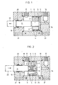
- the piston pump consists of a cylinder 1 and two end parts 14 and 16 screwed to the cylinder 1 by means of connecting screws 21.
- One 14 of the end parts is provided with an inlet 15 for the liquid.
- the piston 2 with the piston rod 11 is arranged to be reciprocable in the cylinder 1.
- the piston 2 is provided on its peripheral surface with annular seals 4.
- the piston 2 is further perforated parallel to its axis, as can be seen from FIG. 3.
- the number of holes 3 can advantageously be three.
- a circular piston cover 5 separate from the piston 2 is provided on the suction side of the piston 2.
- the diameter of the piston cover 5 does not exceed the diameter of the piston 2; it is advantageously a few millimeters smaller than that of the piston 2.
- the piston cover 5 has a neck 6 with an internal thread 7, which passes through a central bore 22 of the piston 2 with play.
- a pin 12 with an external thread 13 of the piston rod 11 is screwed into the neck 6 of the piston cover 5.
- the diameter of the piston rod 11 is larger than that of the pin 12 with an external thread 13 and that of the bore 22 in the piston 2.
- the outside of the neck is coated with Teflon 8 to prevent abrasion.
- connection of the piston cover 5 with the piston rod 11 can be adjusted as desired. This connection is such that the piston cover 5 during the return stroke of the piston 2 against the first End part 14 with inlet 15 is spaced from the piston 2. As a result, an intermediate space 24 for the flow of the liquid through the piston 2 is formed between the piston 2 and the piston cover 5.
- the distance between the piston cover 5 and the piston 2 is at most 2 mm and is given by the fact that the piston rod 11 is supported against the pressure side of the piston 2 and presses it during the return stroke.
- the piston cover 5 lies close to the piston 2, so that the holes 3 in the piston 2 are closed.
- the piston 2 is pulled through the piston rod 11, a gap being formed between the edge of the piston rod 11 facing the piston 2 and the pressure side of the piston 2.
- the liquid is pressed out of the working space of the cylinder 1 via the outlet 17.
- the liquid cannot escape along the inner wall of the cylinder 1 because the piston in the cylinder 1 is sealed by ring-shaped seals 4.
- the liquid can also not flow through the holes 3 in the piston 2 because they are sealed off by the piston cover 5.
- the piston 2 is provided with a raised edge 9 on its suction side.
- the edge of the piston cover is folded inwards on its side facing the piston 2.
- the folded edge 10 of the piston cover 5 comes to rest on the raised edge 9 of the piston 2, so that the piston 2 forms a tight fit with the piston cover 5.
- the outside diameter of the piston cover 5 is somewhat smaller than the outside diameter of the piston 2.
- the second end part 16 has a sealed bore 19 through which the piston rod 11 is passed.
- the piston rod 11 is then connected to a drive shaft 23 of an electric motor (not shown), advantageously eccentrically. With 18 and 20 seals are designated.
- Such a piston pump can, for. B. be used in a device for making whipped cream.
- the cream with air is fed into the pump through the inlet.
- the piston which is driven by an electric motor at 1,500 rpm, reciprocates, the stroke length varying in the range of approximately 10 mm.
- the cream with air sucked into the cylinders is forced out of the cylinder into a homogenizer, in which the blow occurs.
- the pressure in the piston pump is around 6.7 atm.
Abstract
Description
Die Erfindung geht aus von einer Kolbenpumpe für Flüssigkeiten, mit einem Zylinder, in welchem ein Kolben mit einer Kolbenstange hin- und herbewegbar angeordnet ist, durch welche Hin- und Herbewegung die Flüssigkeit über einen Einlass in den Arbeitsraum des Zylinders angesaugt und aus dem Arbeitsraum über einen Auslass gedrückt wird.The invention is based on a piston pump for liquids, with a cylinder, in which a piston with a piston rod is arranged to be able to move back and forth, by means of which back and forth movement the liquid is sucked in via an inlet into the working space of the cylinder and out of the working space an outlet is pushed.
Die Kolbenpumpen dieser Art sind mit Saug- und Druckventilen versehen. Bei Saughub des Kolbens wird die Flüssigkeit durch das Saugventil in den Arbeitsraum des Zylinders angesaugt, beim Druckhub schliesst sich das Saugventil und die Flüssigkeit wird aus dem Arbeitsraum des Zylinders durch das Druckventil, das geöffnet wird, in eine Druckleitung gedrückt. Die Herstellung solcher Ventile verteuert den Preis der Kolbenpumpe. Ausserdem können solche Ventile störungsanfällig sein.The piston pumps of this type are equipped with suction and pressure valves. During the suction stroke of the piston, the liquid is sucked into the working chamber of the cylinder through the suction valve, during the pressure stroke the suction valve closes and the liquid is pressed out of the cylinder working chamber through the pressure valve that is opened into a pressure line. The manufacture of such valves increases the price of the piston pump. In addition, such valves can be prone to failure.
Der im Patentanspruch 1 angegebenen Erfindung liegt die Aufgabe zugrunde, eine Kolbenpumpe für Flüssigkeiten zu schaffen, die ohne Ventile störrungsfrei und zuverlässig arbeitet.The invention specified in
Diese Aufgabe wird bei einer Kolbenpumpe nach dem Oberbegriff des Patentanspruches 1 dadurch gelöst, dass der Kolben parallel zu seiner Achse durchlöchert ist und dass an der Ansaugseite des Kolbens ein vom Kolben separater, kreisrunder Kolbendeckel eines Durchmessers, der höchstens dem Kolbendurchmesser entspricht, vorgesehen ist, der mit der Kolbenstange auf solche Weise einstellbar verbunden ist, dass er beim Druck-und Saughub des Kolbens an demselben dicht anliegt und die Löcher im Kolben abschliesst und beim Rückhub des Kolbens von demselben im Abstand steht, wodurch zwischen dem Kolben und dem Kolbendeckel ein Zwischenraum für den Durchfluss der Flüssigkeit durch den Kolben entsteht.This object is achieved in a piston pump according to the preamble of
Mit Vorteil ist der Kolbendeckel mit einem eine Bohrung des Kolbens frei durchgehenden Hals mit Innengewinde versehen, in welchem ein Zapfen mit Aussengewinde der Kolbenstange eingeschraubt ist. Der Kolbendeckel ist gegenüber dem Kolben so eingestellt, dass der Abstand des Kolbendeckels vom Kolben während des Rückhubes des Kolbens höchstens 2 mm ausmacht, wobei der Kolbenhub variiert.The piston cover is advantageously provided with a neck with an internal thread that runs freely through a bore of the piston and into which a pin with an external thread of the piston rod is screwed. The piston cover is set relative to the piston so that the distance of the piston cover from the piston during the return stroke of the piston is at most 2 mm, the piston stroke varying.
Der Erfindungsgegenstand wird nachstehend anhand der Zeichnung beispielsweise näher erläutert. Es zeigen:
- Fig. 1 einen Längsschnitt der erfindungsgemässen Kolbenpumpe, bei welcher der Kolben beim Druck- und Saughub dargestellt ist,
- Fig. 2 einen Längsschnitt der erfindungsgemässen Kolbenpumpe, bei welcher der Kolben beim Rückhub dargestellt ist und
- Fig. 3 eine perspektivische, gesprengte Darstellung des Kolbens, der Kolbenstange und des Kolbendek-. kels der Kolbenpumpe nach den Fig. 1 und 2.
- 1 shows a longitudinal section of the piston pump according to the invention, in which the piston is shown during the pressure and suction stroke,
- Fig. 2 shows a longitudinal section of the piston pump according to the invention, in which the piston is shown on the return stroke and
- Fig. 3 is a perspective, exploded view of the piston, the piston rod and the piston cover. kels of the piston pump according to FIGS. 1 and 2.
Die in den Figuren dargestellte Kolbenpumpe kann für verschiedene Flüssigkeiten, wie Wasser, Milch, Rahm, verwendet werden.The piston pump shown in the figures can be used for various liquids, such as water, milk, cream.
Die Kolbenpumpe besteht aus einem Zylinder 1 und zwei mit dem Zylinder 1 mittels Verbindungsschrauben 21 verschraubten Abschlussteilen 14 und 16. Der eine 14 der Abschlussteile ist mit einem Einlass 15 für die Flüssigkeit versehen. Durch Abschrauben dieses ersten Abschlussteiles 14 kann in den Zylinder 1 mühelos ein Kolben 2 mit einer Kolbenstange 11 eingfügt werden. Der Kolben 2 mit der Kolbenstange 11 ist im Zylinder 1 hin- und herbewegbar angeordnet. Durch die Ein- und Herbewegung wird die Flüssigkeit über den Einlass 15 im ersten Anschlussteil 14 in den Arbeitsraum des Zylinders 1 angesaugt und aus demselben über einen im Zylinder 1 vorgesehenen Auslass 17 in eine nicht dargestellte Druckleitung gedrückt. Der Kolben 2 ist an seiner Umfangsfläche mit ringförmigen Dichtungen 4 versehen. Der Kolben 2 ist weiter parallel zu seiner Achse durchlöchert, wie aus der Fig. 3 ersichtlich ist. Die Anzahl der Löcher 3 kann vorteilhaft drei sein.The piston pump consists of a
An der Ansaugseite des Kolbens 2 ist ein vom Kolben 2 separater kreisrunder Kolbendeckel 5 vorgesehen. Der Durchmesser des Kolbendeckels 5 überragt nicht den Durchmesser des Kolbens 2; mit Vorteil ist er um einige Milimeter kleiner als derjenige des Kolbens 2. Zwischen dem Umfang des Kolbendeckels 5 und der Innenwand des Zylinders 1 besteht ein freier Zwischenraum. Der Kolbendeckel 5 weist einen Hals 6 mit Innengewinde 7 auf, der eine Mittelbohrung 22 des Kolbens 2 mit Spiel durchgeht. Im Hals 6 des Kolbendeckels 5 ist ein Zapfen 12 mit Aussengewinde 13 der Kolbenstange 11 eingeschraubt. Der Durchmesser der Kolbenstange 11 ist grösser als derjenige des Zapfens 12 mit Aussengewinde 13 und derjenige der Bohrung 22 im Kolben 2. Der Hals ist auf seiner Aussenseite gegen den Abrieb mit Teflon 8 überzogen.On the suction side of the
Die Verbindung des Kolbendeckels 5 mit der Kolbenstange 11 kann je nach Wunsch eingestellt werden. Diese Verbindung ist eine solche, dass der Kolbendeckel 5 während des Rückhubes des Kolbens 2 gegen den ersten Abschlussteil 14 mit Einlass 15 von dem Kolben 2 im Abstand steht. Dadurch wird zwischen dem Kolben 2 und dem Kolbendeckel 5 ein Zwischenraum 24 für den Durchfluss der Flüssigkeit durch den Kolben 2 gebildet. Der Abstand des Kolbendeckels 5 vom Kolben 2 beträgt höchstens 2 mm und ist dadurch gegeben, dass sich die Kolbenstange 11 gegen die Druckseite des Kolbens 2 abstützt und ihn während des Rückhubes drückt. Beim Druck- und Saughub des Kolbens 2 liegt der Kolbendekkel 5 dicht an dem Kolben 2, so dass die Löcher 3 im Kolben 2 abgeschlossen sind. Bei diesem Hub wird der Kolben 2 durch die Kolbenstange 11 gezogen, wobei zwischen dem dem Kolben 2 zugekehrten Rand der Kolbenstange 11 und der Druckseite des Kolbens 2 eine Lücke gebildet wird.The connection of the
Während des Rückhubes des Kolbens 2, wenn zwischen dem Kolbendeckel 5 und der Ansaugseite des Kolbens 2 ein Zwischenraum 24 besteht, fliesst die im Arbeitsraum des Zylinders 1 befindliche Flüssigkeit durch den Zwischenraum 24 zwischen dem Kolbendeckel 5 und dem Kolben 2 und durch die Löcher 3 im Kolben 2 in den Arbeitsraum des Zylinders 1, der einerseits durch die Druckseite des Kolbens 2 begrenzt ist. Während des Rückhubes wird die Flüssigkeit durch den Kolbendeckel 5 nicht durch den Einlass 15 aus dem Arbeitsraum des Zylinders 1 verdrängt, weil der Einlass aus zwei zueinander senkrecht verlaufenden Kanälen besteht, die verhältnismäs- sig einen kleinen Durchmesser aufweisen, so dass die Flüssigkeit durch den Einlass 15 praktisch nicht austreten kann.During the return stroke of the
Während des Druck- und Saughubes des Kolbens 2 wird die Flüssigkeit aus dem Arbeitsraum des Zylinders 1 über den Auslass 17 gedrückt. Bei diesem Hub kann die Flüssigkeit entlang der Innenwand des Zylinders 1 nicht entweichen, weil der Kolben im Zylinder 1 durch ringförmige Dichtungen 4 abgedichtet ist. Die Flüssigkeit kann auch nicht durch die Löcher 3 im Kolben 2 fliessen, weil dieselben durch den Kolbendekkel 5 dicht abgeschlossen sind.During the pressure and suction stroke of the
Der Kolben 2 ist an seiner Ansaugseite mit einem erhöhten Rand 9 versehen. Der Kolbendeckelrand ist an seiner dem Kolben 2 zugekehrten Seite nach innen abgekantet. Während des Druck- und Saughubes des Kolbens 2 kommt der abgekantete Rand 10 des Kolbendeckels 5 zum Liegen an dem erhöhten Rand 9 des Kolbens 2, so dass der Kolben 2 mit dem Kolbendeckel 5 einen Festsitz bildet. Zu diesem Zweck ist es vorteilhaft, wenn der Aussendurchmesser des Kolbendeckels 5 um etwas kleiner ist als der Aussendurchmesser des Kolbens 2.The
Der zweite Abschlussteil 16 weist eine abgedichdete Bohrung 19 auf, durch welche die Kolbenstange 11 durchgeführt ist. Die Kolbenstange 11 ist dann mit einer Antriebswelle 23 eines nicht dargestellten elektrischen Motores, mit Vorteil exzentrisch, verbunden. Mit 18 und 20 sind Dichtungen bezeichnet.The
Alle Teile der oben beschriebenen Kolbenpumpe bestehen aus rostfreiem Stahl.All parts of the piston pump described above are made of stainless steel.
Eine solche Kolbenpumpe kann z. B. in einer Vorrichtung zum Herstellen von Schlag aus Rahm eingesetzt werden. Der Rahm mit Luft wird in die Pumpe durch den Einlass zugeführt. Der durch einen Elektromotor mit 1 500 U/min angetriebene Kolben macht Hin-und Herbewegungen, wobei die Hublänge im Bereich von etwa 10 mm variiert. Der in den Zylindern angesaugte Rahm mit Luft wird aus dem Zylinder in einen Homogenisator gedrängt, in welchem der Schlag entsteht. Der in der Kolbenpumpe herrschende Druck ist von etwa 6,7 atü.Such a piston pump can, for. B. be used in a device for making whipped cream. The cream with air is fed into the pump through the inlet. The piston, which is driven by an electric motor at 1,500 rpm, reciprocates, the stroke length varying in the range of approximately 10 mm. The cream with air sucked into the cylinders is forced out of the cylinder into a homogenizer, in which the blow occurs. The pressure in the piston pump is around 6.7 atm.
Durch die technisch einfachen, störungsunanfälligen Mittel der oben beschriebenen Kolbenpumpe werden die bis jetzt gebräuchlichen Ansaug- und Druckventile eliminiert.Due to the technically simple, trouble-free means of the piston pump described above, the suction and pressure valves that have been used up to now are eliminated.
Claims (7)
Priority Applications (1)
| Application Number | Priority Date | Filing Date | Title |
|---|---|---|---|
| AT83810165T ATE17158T1 (en) | 1982-04-21 | 1983-04-20 | PISTON PUMP FOR LIQUIDS. |
Applications Claiming Priority (2)
| Application Number | Priority Date | Filing Date | Title |
|---|---|---|---|
| CH242082 | 1982-04-21 | ||
| CH2420/82 | 1982-04-21 |
Publications (2)
| Publication Number | Publication Date |
|---|---|
| EP0093691A1 true EP0093691A1 (en) | 1983-11-09 |
| EP0093691B1 EP0093691B1 (en) | 1985-12-27 |
Family
ID=4233390
Family Applications (1)
| Application Number | Title | Priority Date | Filing Date |
|---|---|---|---|
| EP83810165A Expired EP0093691B1 (en) | 1982-04-21 | 1983-04-20 | Piston pump for liquids |
Country Status (3)
| Country | Link |
|---|---|
| EP (1) | EP0093691B1 (en) |
| AT (1) | ATE17158T1 (en) |
| DE (1) | DE3361613D1 (en) |
Cited By (5)
| Publication number | Priority date | Publication date | Assignee | Title |
|---|---|---|---|---|
| US5035440A (en) * | 1989-08-09 | 1991-07-30 | Chappell International, Inc. | Pump |
| US5127804A (en) * | 1989-08-09 | 1992-07-07 | Innovative Bicycle Products, Inc. | Bicycle seat-tube pump with one-way valves |
| FR2689570A1 (en) * | 1992-04-07 | 1993-10-08 | Serac Group | Positive displacement pump. |
| EP0715039A1 (en) | 1994-11-30 | 1996-06-05 | Fischer, Willibald | Shuttering element |
| FR2817848A1 (en) * | 2000-12-12 | 2002-06-14 | Rexam Sofab | ELECTRONIC MICROPUMP |
Citations (9)
| Publication number | Priority date | Publication date | Assignee | Title |
|---|---|---|---|---|
| FR489088A (en) * | 1917-02-16 | 1918-12-13 | Georges Constantinesco | Improvements to pumps |
| DE462509C (en) * | 1926-03-10 | 1928-07-13 | John Coard Franke | Procedure for lifting liquids by means of pumps with scoop pistons |
| CH253083A (en) * | 1946-05-10 | 1948-02-15 | Maier Emilio | Piston pump working with inertia. |
| US2933050A (en) * | 1957-05-23 | 1960-04-19 | Reynolds Oil Well Pumps Inc | Oil well pump |
| FR1323618A (en) * | 1962-02-27 | 1963-04-12 | Further training in piston pumps | |
| FR1592548A (en) * | 1968-06-21 | 1970-05-19 | ||
| US3536424A (en) * | 1968-11-12 | 1970-10-27 | Hydro Seal Ltd | Pump and piston assembly therefor |
| DE2263363A1 (en) * | 1972-12-23 | 1974-07-11 | Canada Tiefbohrgeraete Und Mas | PISTON PUMP, IN PARTICULAR DEEP PUMP |
| DE2628985A1 (en) * | 1976-06-28 | 1977-12-29 | Speck Kolbenpumpen Fabrik | High pressure hot liq. pump piston - has wear resistant low friction guide ring on suction side of seal ring in annular piston groove |
-
1983
- 1983-04-20 DE DE8383810165T patent/DE3361613D1/en not_active Expired
- 1983-04-20 EP EP83810165A patent/EP0093691B1/en not_active Expired
- 1983-04-20 AT AT83810165T patent/ATE17158T1/en not_active IP Right Cessation
Patent Citations (9)
| Publication number | Priority date | Publication date | Assignee | Title |
|---|---|---|---|---|
| FR489088A (en) * | 1917-02-16 | 1918-12-13 | Georges Constantinesco | Improvements to pumps |
| DE462509C (en) * | 1926-03-10 | 1928-07-13 | John Coard Franke | Procedure for lifting liquids by means of pumps with scoop pistons |
| CH253083A (en) * | 1946-05-10 | 1948-02-15 | Maier Emilio | Piston pump working with inertia. |
| US2933050A (en) * | 1957-05-23 | 1960-04-19 | Reynolds Oil Well Pumps Inc | Oil well pump |
| FR1323618A (en) * | 1962-02-27 | 1963-04-12 | Further training in piston pumps | |
| FR1592548A (en) * | 1968-06-21 | 1970-05-19 | ||
| US3536424A (en) * | 1968-11-12 | 1970-10-27 | Hydro Seal Ltd | Pump and piston assembly therefor |
| DE2263363A1 (en) * | 1972-12-23 | 1974-07-11 | Canada Tiefbohrgeraete Und Mas | PISTON PUMP, IN PARTICULAR DEEP PUMP |
| DE2628985A1 (en) * | 1976-06-28 | 1977-12-29 | Speck Kolbenpumpen Fabrik | High pressure hot liq. pump piston - has wear resistant low friction guide ring on suction side of seal ring in annular piston groove |
Cited By (8)
| Publication number | Priority date | Publication date | Assignee | Title |
|---|---|---|---|---|
| US5035440A (en) * | 1989-08-09 | 1991-07-30 | Chappell International, Inc. | Pump |
| US5127804A (en) * | 1989-08-09 | 1992-07-07 | Innovative Bicycle Products, Inc. | Bicycle seat-tube pump with one-way valves |
| FR2689570A1 (en) * | 1992-04-07 | 1993-10-08 | Serac Group | Positive displacement pump. |
| EP0569262A1 (en) * | 1992-04-07 | 1993-11-10 | Serac France | Volumetric pump |
| US5292236A (en) * | 1992-04-07 | 1994-03-08 | Serac France | Positive displacement pump with pivot piston valve |
| EP0715039A1 (en) | 1994-11-30 | 1996-06-05 | Fischer, Willibald | Shuttering element |
| FR2817848A1 (en) * | 2000-12-12 | 2002-06-14 | Rexam Sofab | ELECTRONIC MICROPUMP |
| WO2002047826A1 (en) * | 2000-12-12 | 2002-06-20 | Rexam Dispensing Systems | Electronic micro-pump |
Also Published As
| Publication number | Publication date |
|---|---|
| ATE17158T1 (en) | 1986-01-15 |
| EP0093691B1 (en) | 1985-12-27 |
| DE3361613D1 (en) | 1986-02-06 |
Similar Documents
| Publication | Publication Date | Title |
|---|---|---|
| DE2642642A1 (en) | SUPPLY SYSTEM FOR SUPPLYING A SPRAY GUN WITH PAINT | |
| DE2736532A1 (en) | AUTOMATIC SPRAY DEVICE | |
| DE19921293A1 (en) | Oil supply unit for linear compressor | |
| EP0216043B1 (en) | Apparatus for dispensing a liquid or viscous material | |
| DE2806788A1 (en) | PUMP NOZZLE FOR COMBUSTION MACHINES | |
| DE1291451B (en) | Mixing device for the production of hot water | |
| DE4436479A1 (en) | Air valve with connection device to prevent icing | |
| EP0394383B1 (en) | Hose pump | |
| EP0226070B1 (en) | Pump arrangement for delivering measured quantities of at least two components | |
| DE2255773A1 (en) | DOUBLE ACTING DOSING PUMP | |
| EP0093691A1 (en) | Piston pump for liquids | |
| DE2852749A1 (en) | CONVEYOR PUMP | |
| DE1528401A1 (en) | pump | |
| DE2410766C3 (en) | Adjusting device with an axial adjusting motor, in particular for actuating gas heating valves | |
| EP0007109A1 (en) | Apparatus for metering a solution of chemicals to a stream of liquid | |
| DE1653577A1 (en) | Hydraulic pump in the manner of a pulsating diaphragm pump | |
| DE2134207C2 (en) | Dosing and filling appts. - for viscous and/or stringy liquids | |
| DE2711208A1 (en) | Viscous material metering equipment - generates vacuum in dispensing chamber to compress material before driving out | |
| EP0441100A1 (en) | Device for controlling the exhaust valve of an internal combustion piston engine | |
| DE1528419C3 (en) | Liquid pump | |
| DE942066C (en) | Piston pump | |
| DE2652567A1 (en) | DILUTION DEVICE | |
| EP0280745A1 (en) | Piston diaphragm pump | |
| DE2238327B2 (en) | Device for spraying liquids | |
| DE2448893C2 (en) | Electric sprayer |
Legal Events
| Date | Code | Title | Description |
|---|---|---|---|
| PUAI | Public reference made under article 153(3) epc to a published international application that has entered the european phase |
Free format text: ORIGINAL CODE: 0009012 |
|
| AK | Designated contracting states |
Designated state(s): AT BE CH DE FR GB IT LI LU NL SE |
|
| 17P | Request for examination filed |
Effective date: 19831105 |
|
| GRAA | (expected) grant |
Free format text: ORIGINAL CODE: 0009210 |
|
| AK | Designated contracting states |
Designated state(s): AT BE CH DE FR GB IT LI LU NL SE |
|
| PG25 | Lapsed in a contracting state [announced via postgrant information from national office to epo] |
Ref country code: NL Effective date: 19851227 Ref country code: IT Free format text: LAPSE BECAUSE OF FAILURE TO SUBMIT A TRANSLATION OF THE DESCRIPTION OR TO PAY THE FEE WITHIN THE PRESCRIBED TIME-LIMIT;WARNING: LAPSES OF ITALIAN PATENTS WITH EFFECTIVE DATE BEFORE 2007 MAY HAVE OCCURRED AT ANY TIME BEFORE 2007. THE CORRECT EFFECTIVE DATE MAY BE DIFFERENT FROM THE ONE RECORDED. Effective date: 19851227 Ref country code: BE Effective date: 19851227 |
|
| REF | Corresponds to: |
Ref document number: 17158 Country of ref document: AT Date of ref document: 19860115 Kind code of ref document: T |
|
| PG25 | Lapsed in a contracting state [announced via postgrant information from national office to epo] |
Ref country code: SE Effective date: 19860131 |
|
| REF | Corresponds to: |
Ref document number: 3361613 Country of ref document: DE Date of ref document: 19860206 |
|
| PG25 | Lapsed in a contracting state [announced via postgrant information from national office to epo] |
Ref country code: AT Effective date: 19860420 |
|
| PG25 | Lapsed in a contracting state [announced via postgrant information from national office to epo] |
Ref country code: LU Free format text: LAPSE BECAUSE OF NON-PAYMENT OF DUE FEES Effective date: 19860430 |
|
| ET | Fr: translation filed | ||
| NLV1 | Nl: lapsed or annulled due to failure to fulfill the requirements of art. 29p and 29m of the patents act | ||
| PLBE | No opposition filed within time limit |
Free format text: ORIGINAL CODE: 0009261 |
|
| STAA | Information on the status of an ep patent application or granted ep patent |
Free format text: STATUS: NO OPPOSITION FILED WITHIN TIME LIMIT |
|
| 26N | No opposition filed | ||
| GBPC | Gb: european patent ceased through non-payment of renewal fee | ||
| PG25 | Lapsed in a contracting state [announced via postgrant information from national office to epo] |
Ref country code: GB Effective date: 19881122 |
|
| PGFP | Annual fee paid to national office [announced via postgrant information from national office to epo] |
Ref country code: FR Payment date: 19890308 Year of fee payment: 7 |
|
| PGFP | Annual fee paid to national office [announced via postgrant information from national office to epo] |
Ref country code: DE Payment date: 19890331 Year of fee payment: 7 |
|
| PG25 | Lapsed in a contracting state [announced via postgrant information from national office to epo] |
Ref country code: FR Effective date: 19901228 |
|
| PG25 | Lapsed in a contracting state [announced via postgrant information from national office to epo] |
Ref country code: DE Effective date: 19910101 |
|
| REG | Reference to a national code |
Ref country code: FR Ref legal event code: ST |
|
| PGFP | Annual fee paid to national office [announced via postgrant information from national office to epo] |
Ref country code: CH Payment date: 19970428 Year of fee payment: 15 |
|
| PG25 | Lapsed in a contracting state [announced via postgrant information from national office to epo] |
Ref country code: LI Free format text: LAPSE BECAUSE OF NON-PAYMENT OF DUE FEES Effective date: 19980430 Ref country code: CH Free format text: LAPSE BECAUSE OF NON-PAYMENT OF DUE FEES Effective date: 19980430 |
|
| REG | Reference to a national code |
Ref country code: CH Ref legal event code: PL |