EP0093588A1 - Verstärktes hydraulisches Bremssystem - Google Patents
Verstärktes hydraulisches Bremssystem Download PDFInfo
- Publication number
- EP0093588A1 EP0093588A1 EP83302418A EP83302418A EP0093588A1 EP 0093588 A1 EP0093588 A1 EP 0093588A1 EP 83302418 A EP83302418 A EP 83302418A EP 83302418 A EP83302418 A EP 83302418A EP 0093588 A1 EP0093588 A1 EP 0093588A1
- Authority
- EP
- European Patent Office
- Prior art keywords
- pressure
- actuated
- full power
- master cylinder
- circuit
- Prior art date
- Legal status (The legal status is an assumption and is not a legal conclusion. Google has not performed a legal analysis and makes no representation as to the accuracy of the status listed.)
- Granted
Links
- 239000012530 fluid Substances 0.000 claims abstract description 9
- 230000009977 dual effect Effects 0.000 claims description 7
- 238000010276 construction Methods 0.000 abstract description 4
- 238000009834 vaporization Methods 0.000 abstract description 2
- 238000006073 displacement reaction Methods 0.000 description 4
- 230000000712 assembly Effects 0.000 description 1
- 238000000429 assembly Methods 0.000 description 1
- 230000002706 hydrostatic effect Effects 0.000 description 1
- 230000003068 static effect Effects 0.000 description 1
Images
Classifications
-
- B—PERFORMING OPERATIONS; TRANSPORTING
- B60—VEHICLES IN GENERAL
- B60T—VEHICLE BRAKE CONTROL SYSTEMS OR PARTS THEREOF; BRAKE CONTROL SYSTEMS OR PARTS THEREOF, IN GENERAL; ARRANGEMENT OF BRAKING ELEMENTS ON VEHICLES IN GENERAL; PORTABLE DEVICES FOR PREVENTING UNWANTED MOVEMENT OF VEHICLES; VEHICLE MODIFICATIONS TO FACILITATE COOLING OF BRAKES
- B60T13/00—Transmitting braking action from initiating means to ultimate brake actuator with power assistance or drive; Brake systems incorporating such transmitting means, e.g. air-pressure brake systems
- B60T13/10—Transmitting braking action from initiating means to ultimate brake actuator with power assistance or drive; Brake systems incorporating such transmitting means, e.g. air-pressure brake systems with fluid assistance, drive, or release
- B60T13/12—Transmitting braking action from initiating means to ultimate brake actuator with power assistance or drive; Brake systems incorporating such transmitting means, e.g. air-pressure brake systems with fluid assistance, drive, or release the fluid being liquid
- B60T13/14—Transmitting braking action from initiating means to ultimate brake actuator with power assistance or drive; Brake systems incorporating such transmitting means, e.g. air-pressure brake systems with fluid assistance, drive, or release the fluid being liquid using accumulators or reservoirs fed by pumps
- B60T13/142—Systems with master cylinder
- B60T13/145—Master cylinder integrated or hydraulically coupled with booster
- B60T13/146—Part of the system directly actuated by booster pressure
Definitions
- This invention relates to a boosted hydraulic braking system for vehicles.
- Braking systems which comprise a booster and a master cylinder and wherein a servo device magnifies the actuating pedal displacement as well as the input effort whereby, in the event of failure of the servo power, the brakes can be applied or operated without excessive pedal effort.
- Our earlier British Patent specification No. 1,333,050 describes a booster particularly suitable for the actuation of a braking system incorporating two independent sets of brakes.
- a single master cylinder controls a full power valve which provides pressurised fluid from an accumulator. to actuate one set of brakes and also to boost the master cylinder output to actuate a second set of brakes.
- the boosting is arranged so as to reduce both the load and the travel of the brake pedal (which operates the master cylinder) thus allowing a longer travel and hence a better mechanical advantage in the event of power failure when the master cylinder output directly operates one set of brakes.
- the boost piston has a diameter greater than the diameter of the piston rod, and is operable to produce a boosted pressure equal to the full power pressure.
- a boosted dual hydraulic braking system comprising a pedal actuated master cylinder and a booster, one braking circuit being actuated by a full power system under the control of valve means operable by the master cylinder and the other braking circuit being actuated by the boosted output of the master cylinder at a pressure lower than and, in the preferred embodiment a constant proportion of, that of the full power system.
- the dual circuit braking system may be split vertically or horizontally
- a particularly advantageous application is that of the typical modern passenger car, having a vertically split braking system, one circuit feeding front disc brakes and the other feeding rear disc or drum brakes. It is possible to increase the working pressure in the front disc brake circuit without altering the pressure in the rear brake circuit by means of this invention. This enables the pistons in the front disc calipers, or the discs themselves, to be reduced in diameter, leading to space and weight saving. Such an increased pressure can lead to increased compliance in the front brake hoses, which could give excessive pedal travel with a conventional boosted system. By using full power pressure in the front circuit, (from the accumulator, metered by the power valve), this increased compliance is not significant. The rear brakes are operated at a lower pressure by the boosted circuit, so that compliance and hence pedal travel are reduced.
- one advantage of this invention is that it allows the front disc brake and caliper assemblies to be reduced in size by operating at higher pressure, whilst retaining the lower pressure for the rear brakes and thus avoiding excessive compliance. Furthermore, as rear brakes generally do less work than front brakes, due to higher static loading of the front axle and also dynamic weight transfer, they tend to be smaller at present, so that this invention could reduce front brakes to the same size as rear brakes, leading to commonality of parts and also enabling wheel sizes to be reduced as the front brake size tends to limit wheel size at present.
- Another advantage is that by providing a full power circuit to the front brakes these could be allowed to run hotter as vapourisation of the fluid is far less likely to cause problems with full power than with a conventional hydrostatic circuit.
- the same brakes could be used front and rear, running at higher pressures and temperatures at the front.
- booster piston may be simplified so that the full power pressure acts on the piston rod area and the piston itself can now be dispensed with, together with the close tolerance which would otherwise be required to achieve boosted output pressure equal to the full power pressure, leading to substantial cost, weight and space saving.
- a booster for a dual hydraulic braking system comprising a servo or boost piston actuated by pressure fluid in the full power system and adapted, in response to said pressure, to abut and displace a piston element which is simultaneously responsive, to produce the boosted output actuating the other braking circuit, to the pressure generated by the master cylinder acting on an annular region thereof surrounding the area engaged by the boost piston, wherein the area engaged by the boost piston is equal to the area thereof acted on by the pressure in the said full power circuit.
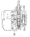
- the booster shown in the drawing includes a master cylinder 10 which is pedal actuated through a suitable connection 12 and in communication with a reservoir 14 for hydraulic fluid.
- valve "crack-off" This initial operation of the power valve by means of the pre-loaded spring is known as valve "crack-off", its function being to provide an initial pressure to move the boost piston 32 so that the recuperating valve 34 is closed. Any back pressure generated in the master cylinder 10 by this movement of the boost 32 and output 36 pistons is dissipated through a tilt valve (not shown but fitted in the region) 38 into the master cylinder reservoir.
- the power delivery pressure which is applied to one of the brake circuits also acts on the boost piston to push the output piston, with the help of the. manual pressure over an annular area, to produce a boosted output pressure, which is applied to the other brake circuit.
- the power valve cannot be operated until pressure is generated in the master cylinder 10, which means the tilt valve 38 must be closed.
- Initial movement of the boost piston 32 displaces fluid through the recuperating valve 34 in the output piston 36 and this displacement goes into the master cylinder 10, causing a sudden pressure increase which is felt as a kick-back on the pedal.
- the nudge spring is to prevent this kick-back by ensuring this initial displacement pulse takes place whilst the tilt valve 38 is still open, allowing the fluid to go to the reservoir, without generating appreciable pressure.
- the recuperating valve 34 has shut the displacement ceases and the tilt valve 38 can then be closed.
- the boosted output pressure is made equal to (balanced) the full power pressure by appropriate selection of the effective areas upon which pressure act.
- the boost piston is made larger in diameter than the piston rod.
- the booster of this invention has a much simplified, construction, the area of the boost piston on which the full power pressure acts being equal to the area of the opposite end of the boost piston which bears upon the output piston.
Landscapes
- Engineering & Computer Science (AREA)
- Transportation (AREA)
- Mechanical Engineering (AREA)
- Braking Systems And Boosters (AREA)
Applications Claiming Priority (2)
| Application Number | Priority Date | Filing Date | Title |
|---|---|---|---|
| GB8212243 | 1982-04-28 | ||
| GB8212243 | 1982-04-28 |
Publications (2)
| Publication Number | Publication Date |
|---|---|
| EP0093588A1 true EP0093588A1 (de) | 1983-11-09 |
| EP0093588B1 EP0093588B1 (de) | 1986-08-13 |
Family
ID=10530016
Family Applications (1)
| Application Number | Title | Priority Date | Filing Date |
|---|---|---|---|
| EP19830302418 Expired EP0093588B1 (de) | 1982-04-28 | 1983-04-28 | Verstärktes hydraulisches Bremssystem |
Country Status (3)
| Country | Link |
|---|---|
| EP (1) | EP0093588B1 (de) |
| DE (1) | DE3365257D1 (de) |
| GB (1) | GB2120334A (de) |
Citations (2)
| Publication number | Priority date | Publication date | Assignee | Title |
|---|---|---|---|---|
| GB1017500A (en) * | 1963-10-03 | 1966-01-19 | Bendix Corp | Power brake means |
| GB1333050A (en) * | 1969-12-19 | 1973-10-10 | Dewandre Co Ltd C | Boosted hydraulic braking systems |
Family Cites Families (5)
| Publication number | Priority date | Publication date | Assignee | Title |
|---|---|---|---|---|
| GB580283A (en) * | 1944-04-28 | 1946-09-03 | Automotive Prod Co Ltd | Improvements in or relating to liquid pressure servo-motor devices |
| GB580638A (en) * | 1944-12-11 | 1946-09-13 | Automotive Prod Co Ltd | Improvements in or relating to braking systems for vehicles |
| GB622617A (en) * | 1947-04-01 | 1949-05-04 | Automotive Prod Co Ltd | Improvements in or relating to liquid pressure braking systems |
| DE2038870B2 (de) * | 1970-08-05 | 1977-08-11 | Erno-Raumfahrttechnik Gmbh, 2800 Bremen | Vorrichtung zur durchfuehrung ozeanographischer und meteorologischer messungen in schelfgebieten |
| US3817037A (en) * | 1971-12-24 | 1974-06-18 | Itt | Master cylinder for two-circuit brake systems |
-
1983
- 1983-04-28 GB GB08311594A patent/GB2120334A/en not_active Withdrawn
- 1983-04-28 DE DE8383302418T patent/DE3365257D1/de not_active Expired
- 1983-04-28 EP EP19830302418 patent/EP0093588B1/de not_active Expired
Patent Citations (2)
| Publication number | Priority date | Publication date | Assignee | Title |
|---|---|---|---|---|
| GB1017500A (en) * | 1963-10-03 | 1966-01-19 | Bendix Corp | Power brake means |
| GB1333050A (en) * | 1969-12-19 | 1973-10-10 | Dewandre Co Ltd C | Boosted hydraulic braking systems |
Also Published As
| Publication number | Publication date |
|---|---|
| GB2120334A (en) | 1983-11-30 |
| GB8311594D0 (en) | 1983-06-02 |
| EP0093588B1 (de) | 1986-08-13 |
| DE3365257D1 (en) | 1986-09-18 |
Similar Documents
| Publication | Publication Date | Title |
|---|---|---|
| US3976171A (en) | Dual-circuit brake system | |
| US4225022A (en) | Brake booster | |
| US3559406A (en) | Vehicle braking system | |
| US5036960A (en) | Apparatus and method of automotive brake with booster piston | |
| US3894390A (en) | Brake valve for an ancillary brake force device in motor vehicles | |
| US4534171A (en) | Hydraulic dual-circuit tandem main brake cylinder | |
| US4223953A (en) | Anti-compounding brake system and valve for hydraulic cam brake actuators | |
| US3768608A (en) | Hydraulic spring brake control system | |
| US4078385A (en) | Brake power boosting mechanism | |
| US3978669A (en) | Servo-power-assisted hydraulic brake-actuating arrangement | |
| US5024298A (en) | Apparatus and method of automotive brake with booster piston | |
| US4137718A (en) | Power brake unit | |
| US4726629A (en) | Hydraulic brake-power booster unit | |
| US3106874A (en) | Control valve actuating structure | |
| GB2128279A (en) | Hydraulic brake master cylinder and booster arrangement | |
| US4313642A (en) | Control valve for vehicle brake systems having two brake circuits | |
| US3852962A (en) | Master cylinder partial system displacement modifier | |
| EP0093588B1 (de) | Verstärktes hydraulisches Bremssystem | |
| US5480222A (en) | Automotive hydraulic braking system | |
| US3703079A (en) | Hydraulic actuating systems | |
| US3114581A (en) | Brake system | |
| EP0065345B1 (de) | Fahrzeugbremsverstärker | |
| US4214448A (en) | Hydraulic brake booster | |
| US4217004A (en) | Controlling means for a dual vehicle hydraulic braking system | |
| US3393945A (en) | Fluid pressure delivery valve |
Legal Events
| Date | Code | Title | Description |
|---|---|---|---|
| PUAI | Public reference made under article 153(3) epc to a published international application that has entered the european phase |
Free format text: ORIGINAL CODE: 0009012 |
|
| AK | Designated contracting states |
Designated state(s): DE FR GB |
|
| 17P | Request for examination filed |
Effective date: 19830926 |
|
| GRAA | (expected) grant |
Free format text: ORIGINAL CODE: 0009210 |
|
| AK | Designated contracting states |
Kind code of ref document: B1 Designated state(s): DE FR GB |
|
| ET | Fr: translation filed | ||
| REF | Corresponds to: |
Ref document number: 3365257 Country of ref document: DE Date of ref document: 19860918 |
|
| PLBE | No opposition filed within time limit |
Free format text: ORIGINAL CODE: 0009261 |
|
| STAA | Information on the status of an ep patent application or granted ep patent |
Free format text: STATUS: NO OPPOSITION FILED WITHIN TIME LIMIT |
|
| 26N | No opposition filed | ||
| PGFP | Annual fee paid to national office [announced via postgrant information from national office to epo] |
Ref country code: GB Payment date: 19920416 Year of fee payment: 10 |
|
| PGFP | Annual fee paid to national office [announced via postgrant information from national office to epo] |
Ref country code: DE Payment date: 19920428 Year of fee payment: 10 |
|
| PGFP | Annual fee paid to national office [announced via postgrant information from national office to epo] |
Ref country code: FR Payment date: 19920430 Year of fee payment: 10 |
|
| PG25 | Lapsed in a contracting state [announced via postgrant information from national office to epo] |
Ref country code: GB Effective date: 19930428 |
|
| GBPC | Gb: european patent ceased through non-payment of renewal fee |
Effective date: 19930428 |
|
| PG25 | Lapsed in a contracting state [announced via postgrant information from national office to epo] |
Ref country code: FR Effective date: 19931229 |
|
| PG25 | Lapsed in a contracting state [announced via postgrant information from national office to epo] |
Ref country code: DE Effective date: 19940101 |
|
| REG | Reference to a national code |
Ref country code: FR Ref legal event code: ST |