EP0093529A2 - Zink-Chlorid-Batterie enthaltende Anlage zur Herstellung/Verbrauch von Chlor - Google Patents
Zink-Chlorid-Batterie enthaltende Anlage zur Herstellung/Verbrauch von Chlor Download PDFInfo
- Publication number
- EP0093529A2 EP0093529A2 EP83302152A EP83302152A EP0093529A2 EP 0093529 A2 EP0093529 A2 EP 0093529A2 EP 83302152 A EP83302152 A EP 83302152A EP 83302152 A EP83302152 A EP 83302152A EP 0093529 A2 EP0093529 A2 EP 0093529A2
- Authority
- EP
- European Patent Office
- Prior art keywords
- chlorine
- gas
- energy storage
- cell
- zinc
- Prior art date
- Legal status (The legal status is an assumption and is not a legal conclusion. Google has not performed a legal analysis and makes no representation as to the accuracy of the status listed.)
- Withdrawn
Links
- 239000000460 chlorine Substances 0.000 title claims abstract description 128
- 229910052801 chlorine Inorganic materials 0.000 title claims abstract description 128
- ZAMOUSCENKQFHK-UHFFFAOYSA-N Chlorine atom Chemical compound [Cl] ZAMOUSCENKQFHK-UHFFFAOYSA-N 0.000 title claims abstract description 127
- JIAARYAFYJHUJI-UHFFFAOYSA-L zinc dichloride Chemical compound [Cl-].[Cl-].[Zn+2] JIAARYAFYJHUJI-UHFFFAOYSA-L 0.000 title claims abstract description 108
- 239000011592 zinc chloride Substances 0.000 title claims abstract description 54
- 235000005074 zinc chloride Nutrition 0.000 title claims abstract description 54
- 229960001939 zinc chloride Drugs 0.000 title claims abstract description 54
- 238000007599 discharging Methods 0.000 claims abstract description 29
- 239000003792 electrolyte Substances 0.000 claims abstract description 28
- 239000013589 supplement Substances 0.000 claims abstract description 24
- 230000003750 conditioning effect Effects 0.000 claims abstract description 15
- 210000004027 cell Anatomy 0.000 claims description 96
- 238000004146 energy storage Methods 0.000 claims description 59
- KZBUYRJDOAKODT-UHFFFAOYSA-N Chlorine Chemical compound ClCl KZBUYRJDOAKODT-UHFFFAOYSA-N 0.000 claims description 45
- 210000000352 storage cell Anatomy 0.000 claims description 39
- 238000000034 method Methods 0.000 claims description 13
- 238000012545 processing Methods 0.000 claims description 7
- 239000012267 brine Substances 0.000 claims description 4
- 229910052736 halogen Inorganic materials 0.000 claims description 4
- HPALAKNZSZLMCH-UHFFFAOYSA-M sodium;chloride;hydrate Chemical compound O.[Na+].[Cl-] HPALAKNZSZLMCH-UHFFFAOYSA-M 0.000 claims description 4
- 150000002367 halogens Chemical class 0.000 claims description 3
- 238000005086 pumping Methods 0.000 claims 3
- 150000002500 ions Chemical class 0.000 claims 1
- 239000007789 gas Substances 0.000 description 22
- HEMHJVSKTPXQMS-UHFFFAOYSA-M Sodium hydroxide Chemical compound [OH-].[Na+] HEMHJVSKTPXQMS-UHFFFAOYSA-M 0.000 description 12
- 239000003513 alkali Substances 0.000 description 11
- 238000004519 manufacturing process Methods 0.000 description 9
- UFHFLCQGNIYNRP-UHFFFAOYSA-N Hydrogen Chemical compound [H][H] UFHFLCQGNIYNRP-UHFFFAOYSA-N 0.000 description 7
- 230000005611 electricity Effects 0.000 description 7
- 238000012546 transfer Methods 0.000 description 6
- XLYOFNOQVPJJNP-UHFFFAOYSA-N water Substances O XLYOFNOQVPJJNP-UHFFFAOYSA-N 0.000 description 6
- 238000003860 storage Methods 0.000 description 5
- 238000013461 design Methods 0.000 description 4
- 238000010586 diagram Methods 0.000 description 4
- 239000001257 hydrogen Substances 0.000 description 4
- 229910052739 hydrogen Inorganic materials 0.000 description 4
- VNWKTOKETHGBQD-UHFFFAOYSA-N methane Chemical compound C VNWKTOKETHGBQD-UHFFFAOYSA-N 0.000 description 4
- 235000011121 sodium hydroxide Nutrition 0.000 description 4
- ICGLOTCMOYCOTB-UHFFFAOYSA-N [Cl].[Zn] Chemical compound [Cl].[Zn] ICGLOTCMOYCOTB-UHFFFAOYSA-N 0.000 description 3
- 239000002253 acid Substances 0.000 description 3
- 238000005868 electrolysis reaction Methods 0.000 description 3
- 239000007788 liquid Substances 0.000 description 3
- 229910052751 metal Inorganic materials 0.000 description 3
- 239000002184 metal Substances 0.000 description 3
- 239000000126 substance Substances 0.000 description 3
- CURLTUGMZLYLDI-UHFFFAOYSA-N Carbon dioxide Chemical compound O=C=O CURLTUGMZLYLDI-UHFFFAOYSA-N 0.000 description 2
- WCUXLLCKKVVCTQ-UHFFFAOYSA-M Potassium chloride Chemical compound [Cl-].[K+] WCUXLLCKKVVCTQ-UHFFFAOYSA-M 0.000 description 2
- QAOWNCQODCNURD-UHFFFAOYSA-N Sulfuric acid Chemical compound OS(O)(=O)=O QAOWNCQODCNURD-UHFFFAOYSA-N 0.000 description 2
- HCHKCACWOHOZIP-UHFFFAOYSA-N Zinc Chemical compound [Zn] HCHKCACWOHOZIP-UHFFFAOYSA-N 0.000 description 2
- 230000003247 decreasing effect Effects 0.000 description 2
- 238000011161 development Methods 0.000 description 2
- 238000005265 energy consumption Methods 0.000 description 2
- 230000002349 favourable effect Effects 0.000 description 2
- ACXCKRZOISAYHH-UHFFFAOYSA-N molecular chlorine hydrate Chemical compound O.ClCl ACXCKRZOISAYHH-UHFFFAOYSA-N 0.000 description 2
- 239000003345 natural gas Substances 0.000 description 2
- 239000000376 reactant Substances 0.000 description 2
- 239000007787 solid Substances 0.000 description 2
- 229910052725 zinc Inorganic materials 0.000 description 2
- 239000011701 zinc Substances 0.000 description 2
- -1 Halogen Hydrates Chemical class 0.000 description 1
- DGAQECJNVWCQMB-PUAWFVPOSA-M Ilexoside XXIX Chemical compound C[C@@H]1CC[C@@]2(CC[C@@]3(C(=CC[C@H]4[C@]3(CC[C@@H]5[C@@]4(CC[C@@H](C5(C)C)OS(=O)(=O)[O-])C)C)[C@@H]2[C@]1(C)O)C)C(=O)O[C@H]6[C@@H]([C@H]([C@@H]([C@H](O6)CO)O)O)O.[Na+] DGAQECJNVWCQMB-PUAWFVPOSA-M 0.000 description 1
- BNOODXBBXFZASF-UHFFFAOYSA-N [Na].[S] Chemical compound [Na].[S] BNOODXBBXFZASF-UHFFFAOYSA-N 0.000 description 1
- 239000003990 capacitor Substances 0.000 description 1
- 239000001569 carbon dioxide Substances 0.000 description 1
- 229910002092 carbon dioxide Inorganic materials 0.000 description 1
- 239000003518 caustics Substances 0.000 description 1
- 238000012993 chemical processing Methods 0.000 description 1
- 238000002485 combustion reaction Methods 0.000 description 1
- 230000001143 conditioned effect Effects 0.000 description 1
- 238000010276 construction Methods 0.000 description 1
- 238000001816 cooling Methods 0.000 description 1
- 238000012937 correction Methods 0.000 description 1
- 230000001419 dependent effect Effects 0.000 description 1
- 230000000694 effects Effects 0.000 description 1
- 238000012983 electrochemical energy storage Methods 0.000 description 1
- 239000008151 electrolyte solution Substances 0.000 description 1
- 238000012994 industrial processing Methods 0.000 description 1
- LWRYTNDOEJYQME-UHFFFAOYSA-N lithium;sulfanylideneiron Chemical compound [Li].[Fe]=S LWRYTNDOEJYQME-UHFFFAOYSA-N 0.000 description 1
- 238000012423 maintenance Methods 0.000 description 1
- QSHDDOUJBYECFT-UHFFFAOYSA-N mercury Chemical compound [Hg] QSHDDOUJBYECFT-UHFFFAOYSA-N 0.000 description 1
- 229910052753 mercury Inorganic materials 0.000 description 1
- 238000012986 modification Methods 0.000 description 1
- 230000004048 modification Effects 0.000 description 1
- 238000011017 operating method Methods 0.000 description 1
- 239000001103 potassium chloride Substances 0.000 description 1
- 235000011164 potassium chloride Nutrition 0.000 description 1
- 239000000047 product Substances 0.000 description 1
- 238000011160 research Methods 0.000 description 1
- 238000013341 scale-up Methods 0.000 description 1
- 239000011780 sodium chloride Substances 0.000 description 1
- FAPWRFPIFSIZLT-UHFFFAOYSA-M sodium chloride Inorganic materials [Na+].[Cl-] FAPWRFPIFSIZLT-UHFFFAOYSA-M 0.000 description 1
- 239000000243 solution Substances 0.000 description 1
Images
Classifications
-
- H—ELECTRICITY
- H01—ELECTRIC ELEMENTS
- H01M—PROCESSES OR MEANS, e.g. BATTERIES, FOR THE DIRECT CONVERSION OF CHEMICAL ENERGY INTO ELECTRICAL ENERGY
- H01M10/00—Secondary cells; Manufacture thereof
- H01M10/42—Methods or arrangements for servicing or maintenance of secondary cells or secondary half-cells
- H01M10/4214—Arrangements for moving electrodes or electrolyte
-
- C—CHEMISTRY; METALLURGY
- C25—ELECTROLYTIC OR ELECTROPHORETIC PROCESSES; APPARATUS THEREFOR
- C25B—ELECTROLYTIC OR ELECTROPHORETIC PROCESSES FOR THE PRODUCTION OF COMPOUNDS OR NON-METALS; APPARATUS THEREFOR
- C25B15/00—Operating or servicing cells
-
- Y—GENERAL TAGGING OF NEW TECHNOLOGICAL DEVELOPMENTS; GENERAL TAGGING OF CROSS-SECTIONAL TECHNOLOGIES SPANNING OVER SEVERAL SECTIONS OF THE IPC; TECHNICAL SUBJECTS COVERED BY FORMER USPC CROSS-REFERENCE ART COLLECTIONS [XRACs] AND DIGESTS
- Y02—TECHNOLOGIES OR APPLICATIONS FOR MITIGATION OR ADAPTATION AGAINST CLIMATE CHANGE
- Y02E—REDUCTION OF GREENHOUSE GAS [GHG] EMISSIONS, RELATED TO ENERGY GENERATION, TRANSMISSION OR DISTRIBUTION
- Y02E60/00—Enabling technologies; Technologies with a potential or indirect contribution to GHG emissions mitigation
- Y02E60/10—Energy storage using batteries
Definitions
- the present invention relates generally to zinc-chlorine battery systems and chlorine producing/consuming plants. More particularly the invention relates to an advantageous combination of zinc-chlorine battery stack and a chlorine producing or consuming plant.
- the electricity generated for peak demand is supplied from diesel engines and combustion turbines, which are fired by distillate oil and natural gas.
- One such method is the use of secondary energy storage batteries to store electricity generated from utility baseload facilities during the night or off-peak hours, and discharging these batteries during the hours of peak demand.
- Secondary energy storage batteries which could be considered for this application include lead-acid, lithium-iron sulfide, sodium sulfur, and zinc-chloride batteries.
- electric utilities will comprise the principal users of "peak-shaving" or "load-leveling" battery plants for service in the sub-transmission network of the utilities, it may be economically advantageous for industrial customers of the electric utilities to also employ battery plants. Due at least in part to the operating and maintenance costs associated with the peak demand generating engines, the electric utilities typically charge a premium or place a surcharge on the electricity supplied to their industrial customers over the peak period. This surcharge is substantial and can amount to several times the normal kilo-watt hour rate charged by the utilities for off-peak electrical energy consumption. Accordingly, industries which consume large amounts of electrical energy may achieve significant savings by employing one or more battery plants to supply or supplement the electricity required during on-peak electrical energy consuming hours.
- chlor-alkali One industry which is known to require large amounts of electrical power is the "chlor-alkali” industry. This industry refers to the manufacture of chlorine and alkali caustic from electrolytic cells which generate chlorine gas, hydrogen gas and caustic soda from a steady supply of brine electrolytic solution. Banks of these cells are employed in a typical manufacturing plant, and since each cell normally consumes between ten to thirty thousand amperes, the electrical power required to operate a chlor-alkali plant is substantial.
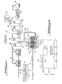
- Figure 1 is a simplified schematic diagram of a chlorine producing facility employing a combination of electrolytic cells and zinc-chloride battery stacks according to the present invention.
- Figure 2 is a graph comparing the electrical power required over a twenty-four hour period by a chlorine producing plant which does employ energy storage and a chlorine producing plant which does not employ energy storage.
- Figure 3 is a graph comparing the cost of the electrical power consumed over a twenty-four hour period for a chlorine producing plant which does employ energy storage and a chlorine producing plant which does not employ energy storage.
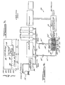
- FIG. 4 is a simplified schematic diagram of a chlorine using facility employing zinc-chloride battery stacks according to the present invention.
- the present invention concerns an approved gas producing plant having at least one electrolytic cell adapted to generate the gas in combination with at least one secondary energy storage cell capable of generating the gas during a first cycle portion and consuming the gas during a second cycle portion.
- Suitable conduit means is provided for permitting the secondary energy storage cell to supplement the amount of the gas generated by the electrolytic cell during the first cycle portion, and for permitting the electrolytic cell to supply the gas to the secondary energy storage cell during the second cycle portion.
- the present invention concerns an improved chlorine producing plant having at least one electrolytic cell adapted to generate chlorine in combination with a zinc-chloride battery stack.
- conduit means is provided for permitting the chlorine generated by the battery stack during the charging of the battery stack to supplement the amount of chlorine generated by the electrolytic cell, and for permitting the electrolytic cell to supply chlorine to the battery stack during the discharge of the battery stack.
- power conditioning means may be interposed between the electrolytic cell and the zinc-chloride battery stack for permitting the zinc-chloride battery stack to supplement the supply of electrical power to the electrolytic cell during the discharging of the battery stack.
- the zinc-chloride battery stack is charged substantially during off-peak electrical energy consuming hours and discharged substantially during on-peak electrical energy consuming hours.
- the principles of the present invention are also applicable to chlorine consuming plants having a means for conveying chlorine from a source of chlorine, such as a tank car containing liquefied chlorine.
- a zinc-chloride battery stack is provided in combination with conduit means for permitting the chlorine generated by the battery stack during the charging of the battery stack to supplement the amount of chlorine to the chlorine consuming plant, and for permitting the conveying means to supply chlorine to the battery stack during the discharging of the battery stack.
- the chlorine producing plant 10 includes a plurality of electrolytic cells 12 and 14 which are adapted to generate chlorine gas from a steady supply of brine solution.
- the electrolytic cells 12 and 14 may be comprised of diaphragm, mercury or other conventional electrolytic cells of this type.
- sodium or potassium chloride brine is fed into the anode compartment and flows through a cell diaphragm into the cathode compartment where alkali is formed.
- Chlorine gas is formed at the anode and hydrogen and alkali (caustic soda) are formed at the cathode of the cell.
- the plant 10 Since chlorine producing electrolytic cells operate from d.c. electrical power, the plant 10 includes suitable power conditioning equipment 16 for converting the a.c. electrical power supplied by the electric utility to the appropriate d.c. electrical power level required by the electrolytic cells.
- a chlorine collection manifold 18 is connected to the chlorine gas outlets at the top of the electrolytic cells 12 and 14 to collect the chlorine gas generated by the cells.
- the chlorine producing plant 10 also includes conventional chlorine processing means which receives the chlorine gas from the chlorine collection manifold 18 and prepares it for storage or shipment. The chlorine gas from the chlorine collection manifold 18 is cooled by direct contact with water in a packed tower 20, and then dried with sulfuric acid in tower 22.
- a gas compressor 24 is provided to increase the pressure (to typically 25 and 100 psi), and then the temperature of the chlorine gas is decreased by cooling units 26, 28 and 30. Any foreign gases which are present with the chlorine gas are subsequently vented and processed through a tail gas separator 32. The chlorine is then properly conditioned for storage in a storage tank 34 and subsequent shipment, such as by tank car 36.
- two subsystems 38 of a normally self contained zinc-chloride battery system are provided in the chlorine producing plant 10 to permit an advantageous transfer of the chlorine gas generated by the electrolytic cells 12 and 14 with the zinc-chloride battery subsystems.
- the zinc-chloride battery subsystems 38 provided are the battery stack and electrolyte circulation subsystems.
- Three battery stacks 40, 42 and 44, are provided, each of which comprises a plurality of the zinc-chloride cells which are connected electrically in the appropriate series and parallel combinations to permit electrical current to flow through the battery stacks.
- Each of the zinc-chloride cells comprises a positive electrode and a negative electrode in contact with an aqueous zinc-chloride electrolyte.
- the means for circulating the electrolyte through the battery stacks 40-44 comprises a sump or reservoir 46-50 containing a supply of electrolyte for each of the battery stacks respectively, and an electrolyte pump 54-56 for each of these respective battery stacks.
- d.c. electrical power is supplied to the battery stacks 40-44 from the power conditioning equipment 16 at the appropriate voltage level necessary to cause electrolysis of the zinc-chloride electrolyte.
- the electrolyte pumps 52-56 operate to circulate the electrolyte contained in the reservoirs 46-50 through the battery stacks. The electrolysis within the cells causes chlorine gas to be liberated or generated at the positive electrodes and zinc metal to be deposited upon the negative electrodes.
- the electrolysis reaction is reversed such that chlorine is consumed at the positive electrodes and the zinc metal is dissolved off the negative electrodes.
- conduit means which permits the chlorine gas generated by the battery stacks 40-44 during charge to supplement the amount of chlorine gas generated by the electrolytic cells 12 and 14, and which permits the electrolytic cells to supply chlorine gas to the battery stacks during discharge.
- the battery stacks 40-44 are provided with a chlorine transferring manifold 58, which is adapted to collect the chlorine gas generated by the battery stacks during charge.
- a valve 60 is provided for controlling the flow of chlorine gas through the manifold 58 to a chlorine transferring conduit 62.
- One end of the conduit 62 is connected to a chlorine conveying conduit 64 which is interposed between the towers 20 and 22.
- the valve 60 is opened to permit the chlorine gas generated by the battery stacks 40-44 to flow to the chlorine processing means (via the manifold 58 and conduits 62 and 64) and combine with the chlorine gas generated by the electrolytic cells 12 and 14.
- a chlorine transferring conduit 66 is provided to permit a portion of the chlorine gas generated by the electrolytic cells 12 and 14 to supply chlorine to the battery stacks 40-44 during the discharging of the battery stacks.
- the chlorine gas generated by the electrolytic cells 12 and 14 passes through the transferring conduits 62 and 66 to the circulating means of each of the battery stacks, where it is combined with the electrolyte being circulated through the battery stacks via electrolyte pumps 52-56.
- a suitable valve 68 is provided to control the flow of chlorine gas through the transferring conduit 66 to the battery stacks 40-44. Accordingly, it will be appreciated that the valve 66 will be closed and the valve 60 will be open during the charging of the battery stacks, and the valve 60 will be closed and the valve 66 will be open during discharge.
- conduit means connecting the battery stack 40-44 with the electrolytic cells 12 and 14 may be suitably varied without departing from the spirit and scope of the present invention.
- the transferring conduit 62 may be directly connected to the chlorine collecting manifold 18 of the electrolytic cells, or the transferring conduit 62 may be connected at other stages in the chlorine processing means, such as to the liquid chlorine storage tank 34.
- the chlorine being supplied to the battery stacks 40-44 during discharge may be in either a gaseous or liquid state.
- valves 60 and 66 may not be required in the appropriate configuration, thereby permitting the direction of the chlorine gas transfer between the battery stacks 40-44 and the electrolytic cells 12 and 14 to be dependent upon only the differences in gas pressure at each end of the conduit means. It should also be appreciated that it may be desirable to provide one or more gas pumps or orifices in the conduit means to more fully control the transfer of chlorine between the electrolytic cells 12 and 14 and the battery stacks 40-44.
- the electrical energy stored in the battery stacks 40-44 may be utilized during discharge in at least three ways according to the present invention.
- the power conditioning equipment 16 operates to place a resistive load across the battery stacks in order to permit the battery stacks to supply or supplement electrical power to the load.
- One way in which the electrical energy stored in the battery stacks may be utilized is to provide the electric utility grid network itself as the load across the battery stacks. In this situation the power conditioning equipment 16 will operate to convert the d.c. electrical power transmitted from the battery stacks 40-44 along power lines 70 to the a.c. power level compatible with the utility power lines 72. This will allow battery stacks 40-44 to function in a "peak shaving" or "load leveling" capacity.
- Another way for the stored electrical energy to be utilized is to provide the electrolytic cells 12 and 14 as the load for the battery stacks 40-44.
- the power conditioning equipment will operate as an electrical interface between the battery stacks 40-44 and the electrolytic cells 12 and 14 to enable the battery stacks to supplement d.c. electrical power to the electrolytic cells in combination with the electrical power supplied by the electrical utility.
- a third way in which the stored electrical energy may be utilized will arise when the electric utility deems it necessary to interrupt the power supplied to the plant 10. In this situation, the power conditioning equipment 16 will operate to permit the battery stacks 40-44 to provide all the electrical power necessary to operate the electrolytic cells 12 and 14, as well as any essential auxiliary equipment in the plant.
- the power conditioning equipment 16 may be generally comprised of one or more thyristor converter bridges for converting a.c. electrical power to d.c. electrical power and d.c. electrical power to a.c. electrical power as required, power factor correction capacitors, a harmonic filter, and the appropriate switch gear to permit electrical power transfer from the battery stacks to the electrolytic cells.
- FIG. 2 is a graph comparing the electrical power required over a twenty-four hour period by the chlorine producing plant 10 and a chlorine producing plant which does not employ energy storage. Without employing energy storage, the energy consumption of a chlorine producing plant will typically be constant due to the characteristics of the electrolytic cells. Generally speaking, electrolytic cells of this type are normally operated at a constant power consumption rate, i.e., the rate corresponding to the most efficient operating condition for the cells. However, when a secondary energy storage battery system according to the present invention is employed in a chlorine producing plant, it is preferred that the battery system be charged substantially during off-peak electrical energy consuming hours and discharged substantially during on-peak electrical energy consuming hours. The typical hours of peak demand for the normal electric utility generally extend from 11:00 a.m.
- the curved portions 76 and 78 of Figure 2 indicate that the electrical power consumed by the plant will increase when the battery stacks 40-44 are charged during the off-peak hours, in comparison with the normal power consumption rate indicated by the broken line 80.
- the curved portion 82 indicates that the power consumption rate will decrease below the normal power consumption rate for the plant.
- Figure 3 graphically depicts the advantageous result achieved by operating the chlorine producing plant 10 in accordance with the method described above.
- Figure 3 is a graph comparing the cost of the electrical power consumed over a twenty four hour period for the chlorine producing plant 10 and a chlorine producing plant which does not employ an energy storage system according to the present invention.
- the broken line 84 represents the normal costs associated with the electrical power consumption during off-peak hours, while the broken line 86 represents the cost associated with electrical power consumption during on-peak hours.
- the curved portion 88 indicates that the cost will increase due to the increased power consumption for the plant.
- the curved portion 90 indicates that the cost for buying electricity will substantially decrease in comparison with the normal cost associated over that time period. It should be noted that no secondary energy storage battery is 100% efficient. Accordingly, a portion of the energy consumed by the plant 10 during the charging of the battery stack 40-44 will not be recovered during discharge. However, it is believed that the magnitude of the savings achieved by employing a secondary energy storage system according to the present invention will be considerably more than the cost of purchasing and maintaining the energy storage equipment itself and the cost resulting from the loss of energy over the battery cycle. Additionally, the use of energy storage as discussed above will also provide a reliable alternative source of power for the chlorine producing plant.
- the operating method described above will also include the steps of controlling the valves to permit the chlorine gas generated during the charging of the battery stacks 40-44 to supplement the amount of chlorine gas generated by the electrolytic cells 12 and 14, and controlling the valves to permit the electrolytic cells to supply chlorine to the battery stacks during the discharging of the battery stacks.
- the valve 60 will be enabled or opened, while the valve 68 will be closed.
- the valve 68 will be enabled or opened, while the valve 60 will be disabled or closed.
- the electrolyte pumps 52-56 may be disabled from circulating electrolyte or turned off when the battery stacks 40-44 are in a standby condition, generally any time other than charge or discharge. With the electrolyte pumps 52-56 turned off, the electrolyte reactants in the battery cells will quickly become depleted, and thereby limit the extent of self discharge possible in the battery stacks. In such a state, the battery stacks 40-44 may stand idle for extended periods of time with only minimal losses of the energy stored during charge.
- the amount of chlorine produced when the battery stacks 40-44 are charged and discharged will generally follow the curved portions 76, 78, and 82, in comparison with the amount of chlorine produced without energy storage as represented by the broken line 80. Since, as in self-contained zinc-chloride battery systems, the amount of chlorine gas generated during the charging of the battery stacks will be the same amount of chlorine required during the discharging of the battery stacks, the plant 10 will generally not experience any net loss or gain in chlorine produced over a battery cycle. It may also be noted that over a battery cycle negligible amounts of hydrogen and carbon dioxide gases are typically liberated from the battery stacks. However, these or other foreign gases from the battery stacks will not affect the plant 10, as they will be removed via the plant's tail gas separator 32.
- a simplified schematic diagram of a chlorine consuming plant 92 is shown.
- the chlorine consuming plant 92 may comprise any industrial or chemical processor requiring the use of chlorine.
- a chlorine consuming plant 10 may comprise a water processing plant which utilizes substantial amounts of chlorine to purify the water for subsequent internal consumption by the public. It should also be noted that water processing plants may require significant amounts of electrical energy to pump the water from a reservoir, river or other water basin to remote consumers.
- the source of chlorine for the chlorine consuming plant 92 is a chlorine liquid containing tank car '36.
- a suitable evaporator 94 is provided to permit the liquid chlorine to return to a gaseous state, and a conveying conduit 96 is provided to facilitate the transfer of chlorine gas from the evaporator 94 to the industrial or chemical processing equipment.
- the chlorine consuming plant 92 is provided with zinc-chloride battery subsystems '38 and suitable conduit means for permitting the chlorine generated by the battery stacks 1 40- 1 44 during charge to supplement the amount of chlorine to the chlorine consuming plant 92, and for permitting the conveying conduit 96 to supply chlorine to the battery stacks during discharge.
- the transferring conduit '66 is not connected to the transferring conduit '62, but rather directly connected to the conveying conduit 96.
- a suitable valve 97 may also be provided in the conveying conduit 96 between the transferring conduits '62 and '66.
- the chlorine consuming plant 92 is also provided with power conditioning equipment 98 which may differ from the power conditioning equipment 16 of the chlorine producing plant 10 in that the chlorine consuming plant 92 will require a.c. electrical power rather than d.c. electrical power. However, the power producing equipment 98 will operate to utilize the electrical energy stored in the battery stacks '40-'44 in a similar manner as discussed above for the chlorine producing plant 10. Accordingly, it will be appreciated that the energy storage operating aspects of the chlorine consuming plant 92 will be similar to those for the chlorine producing plant 10 described above. It should also be noted that as in the case of the chlorine producing plant 10, the chlorine consuming plant 92 will generally experience no net loss or gain over a battery cycle. Thus, the chlorine consuming plant 92 will purchase the same amount of chlorine whether or not the battery stacks '40-'44 are charged and discharged.
- the principle.s of the present invention are applicable to secondary energy storage cells which operate with a changing electrolyte concentration and are capable of generating a gas during a first cycle portion and consuming the gas during a second cycle portion.
- Such a secondary energy storage cell may be combined with an electrolytic cell adapted to generate this gas in a gas producing plant in accordance with the present invention.
- the gas producing plant would include conduit means, in association with the electrolytic cell and the secondary energy storage cell, for permitting the secondary energy storage cell to supplement the amount of the gas generated by the electrolytic cell during the first cycle portion (charge), and for permitting the electrolytic cell to supply the gas to the secondary energy storage cell during the second cycle portion (discharge).
- Such a secondary energy storage cell or system would be a hydrogen/chlorine electrochemical energy storage system, such as described in the Hart U.S. Patent No. 4,124,741 entitled " H ydrogen/Chlorine Electrical Chemical Energy Storage System", which is hereby incorporated by reference.
Landscapes
- Chemical & Material Sciences (AREA)
- Engineering & Computer Science (AREA)
- Chemical Kinetics & Catalysis (AREA)
- Electrochemistry (AREA)
- Materials Engineering (AREA)
- Metallurgy (AREA)
- Organic Chemistry (AREA)
- Manufacturing & Machinery (AREA)
- General Chemical & Material Sciences (AREA)
- Hybrid Cells (AREA)
- Electrolytic Production Of Non-Metals, Compounds, Apparatuses Therefor (AREA)
- Secondary Cells (AREA)
Applications Claiming Priority (2)
| Application Number | Priority Date | Filing Date | Title |
|---|---|---|---|
| US37439582A | 1982-05-03 | 1982-05-03 | |
| US374395 | 1999-08-13 |
Publications (2)
| Publication Number | Publication Date |
|---|---|
| EP0093529A2 true EP0093529A2 (de) | 1983-11-09 |
| EP0093529A3 EP0093529A3 (de) | 1984-06-27 |
Family
ID=23476616
Family Applications (1)
| Application Number | Title | Priority Date | Filing Date |
|---|---|---|---|
| EP83302152A Withdrawn EP0093529A3 (de) | 1982-05-03 | 1983-04-15 | Zink-Chlorid-Batterie enthaltende Anlage zur Herstellung/Verbrauch von Chlor |
Country Status (3)
| Country | Link |
|---|---|
| EP (1) | EP0093529A3 (de) |
| JP (1) | JPS58204185A (de) |
| CA (1) | CA1196951A (de) |
Cited By (2)
| Publication number | Priority date | Publication date | Assignee | Title |
|---|---|---|---|---|
| US6640457B2 (en) | 1999-09-13 | 2003-11-04 | Swagelok Company | Intrinsic gauging for tube fittings |
| EP2453512A1 (de) * | 2010-11-12 | 2012-05-16 | General Electric Company | Systeme, Verfahren und Vorrichtung zur Anfragereaktion von batteriebetriebenen Vorrichtungen |
Family Cites Families (4)
| Publication number | Priority date | Publication date | Assignee | Title |
|---|---|---|---|---|
| FR364847A (fr) * | 1906-04-02 | 1906-08-30 | Eugene Castel | Procédé pour l'électrolysation du chlorure de sodium |
| GB1258502A (de) * | 1969-02-21 | 1971-12-30 | ||
| US4320179A (en) * | 1978-04-03 | 1982-03-16 | Energy Development Associates, Inc. | Transference and purification of halogen and hydrohalic acid in an electrochemical system |
| US4287267A (en) * | 1980-05-27 | 1981-09-01 | Energy Development Associates, Inc. | Zinc-chlorine battery plant system and method |
-
1983
- 1983-03-28 CA CA000424664A patent/CA1196951A/en not_active Expired
- 1983-04-15 EP EP83302152A patent/EP0093529A3/de not_active Withdrawn
- 1983-05-02 JP JP58078121A patent/JPS58204185A/ja active Granted
Cited By (2)
| Publication number | Priority date | Publication date | Assignee | Title |
|---|---|---|---|---|
| US6640457B2 (en) | 1999-09-13 | 2003-11-04 | Swagelok Company | Intrinsic gauging for tube fittings |
| EP2453512A1 (de) * | 2010-11-12 | 2012-05-16 | General Electric Company | Systeme, Verfahren und Vorrichtung zur Anfragereaktion von batteriebetriebenen Vorrichtungen |
Also Published As
| Publication number | Publication date |
|---|---|
| EP0093529A3 (de) | 1984-06-27 |
| JPS58204185A (ja) | 1983-11-28 |
| JPH032955B2 (de) | 1991-01-17 |
| CA1196951A (en) | 1985-11-19 |
Similar Documents
| Publication | Publication Date | Title |
|---|---|---|
| US4534833A (en) | Zinc-chloride battery in a chlorine producing/consuming plant | |
| Poullikkas | A comparative overview of large-scale battery systems for electricity storage | |
| CN113452044B (zh) | 一种含氢与液态金属电池混合储能系统的风力光伏电网调度方法 | |
| US4084038A (en) | Electrical power generation and storage system | |
| Appleby et al. | The CGE circulating zinc/air battery: A practical vehicle power source | |
| CN110190629A (zh) | 一种基于氢燃料电池的孤岛综合能源系统及其控制方法 | |
| CN114583725A (zh) | 基于氢的近零碳排放综合能源系统及其运行优化方法 | |
| CN216107246U (zh) | 一种光、风发电耦合电解水制氢自然平衡生态系统 | |
| US20130154364A1 (en) | Vanadium redox battery energy storage system | |
| CN120272940B (zh) | 耦合光伏可再生能源的混合制氢系统及优化配置方法 | |
| CN115912413A (zh) | 电子设备、离网风电光伏制氢系统及其控制方法 | |
| Kong et al. | Two-stage optimal scheduling of community integrated energy system considering operation sequences of hydrogen energy storage systems | |
| US20230279569A1 (en) | Arrangement to optimize the production of hydrogen | |
| CN115589028A (zh) | 一种氢电耦合储氢发电方仓 | |
| EP0093529A2 (de) | Zink-Chlorid-Batterie enthaltende Anlage zur Herstellung/Verbrauch von Chlor | |
| Xiao et al. | Structure and Capacity Configuration of Substation Microgrid with Hydrogen Energy Storage | |
| CN118981893A (zh) | 一种考虑soec电热老化效应的电-热-氢-氨耦合微网规划方法 | |
| CN114068995B (zh) | 全铁氧化液流电池系统 | |
| JPS6286667A (ja) | 電解液流通型電池システム及びその運転方法 | |
| JPS6229865B2 (de) | ||
| Popel’ et al. | The comparative analysis of systems of long-term electric power storage intended for sources of back-up and emergency power supply, as well as for power plants using renewable energy sources | |
| CN218352262U (zh) | 一种模块式绿电制氢储用系统 | |
| JP2009165225A (ja) | 分散型電力供給装置 | |
| Zaslavskiy et al. | Application of hybrid energy storage systems in remote power grids | |
| CN111695740B (zh) | 一种基于参数控制的主动储能运行方法及系统 |
Legal Events
| Date | Code | Title | Description |
|---|---|---|---|
| PUAI | Public reference made under article 153(3) epc to a published international application that has entered the european phase |
Free format text: ORIGINAL CODE: 0009012 |
|
| AK | Designated contracting states |
Designated state(s): AT DE FR GB IT NL SE |
|
| PUAL | Search report despatched |
Free format text: ORIGINAL CODE: 0009013 |
|
| AK | Designated contracting states |
Designated state(s): AT DE FR GB IT NL SE |
|
| STAA | Information on the status of an ep patent application or granted ep patent |
Free format text: STATUS: THE APPLICATION IS DEEMED TO BE WITHDRAWN |
|
| 18D | Application deemed to be withdrawn |
Effective date: 19850228 |
|
| RIN1 | Information on inventor provided before grant (corrected) |
Inventor name: ROWAN, JOHN WILSON Inventor name: CARR, PETER |