EP0093220B1 - Procédé et installation pour récupérer des combustibles et autres produits dans les déchets en utilisant des tamis à disques - Google Patents
Procédé et installation pour récupérer des combustibles et autres produits dans les déchets en utilisant des tamis à disques Download PDFInfo
- Publication number
- EP0093220B1 EP0093220B1 EP19820630036 EP82630036A EP0093220B1 EP 0093220 B1 EP0093220 B1 EP 0093220B1 EP 19820630036 EP19820630036 EP 19820630036 EP 82630036 A EP82630036 A EP 82630036A EP 0093220 B1 EP0093220 B1 EP 0093220B1
- Authority
- EP
- European Patent Office
- Prior art keywords
- refuse
- disk screen
- overflow
- underflow
- separating
- Prior art date
- Legal status (The legal status is an assumption and is not a legal conclusion. Google has not performed a legal analysis and makes no representation as to the accuracy of the status listed.)
- Expired
Links
- 239000000446 fuel Substances 0.000 title claims abstract description 26
- 238000000034 method Methods 0.000 title claims description 21
- 239000000463 material Substances 0.000 claims abstract description 19
- 229910052782 aluminium Inorganic materials 0.000 claims description 14
- XAGFODPZIPBFFR-UHFFFAOYSA-N aluminium Chemical compound [Al] XAGFODPZIPBFFR-UHFFFAOYSA-N 0.000 claims description 14
- 239000005337 ground glass Substances 0.000 claims description 11
- 229910052751 metal Inorganic materials 0.000 claims description 10
- 239000002184 metal Substances 0.000 claims description 10
- CWYNVVGOOAEACU-UHFFFAOYSA-N Fe2+ Chemical compound [Fe+2] CWYNVVGOOAEACU-UHFFFAOYSA-N 0.000 claims description 8
- 239000002657 fibrous material Substances 0.000 claims description 5
- 230000005291 magnetic effect Effects 0.000 claims description 4
- 230000001419 dependent effect Effects 0.000 claims 1
- 239000011521 glass Substances 0.000 description 26
- 239000006148 magnetic separator Substances 0.000 description 14
- 239000000835 fiber Substances 0.000 description 12
- 239000000203 mixture Substances 0.000 description 7
- 239000007787 solid Substances 0.000 description 7
- 229910010272 inorganic material Inorganic materials 0.000 description 6
- 239000011147 inorganic material Substances 0.000 description 6
- 238000000926 separation method Methods 0.000 description 6
- 239000000428 dust Substances 0.000 description 5
- 238000011084 recovery Methods 0.000 description 5
- 125000006850 spacer group Chemical group 0.000 description 5
- 239000000123 paper Substances 0.000 description 4
- 230000008569 process Effects 0.000 description 4
- 229910010293 ceramic material Inorganic materials 0.000 description 3
- 238000010586 diagram Methods 0.000 description 3
- 239000000284 extract Substances 0.000 description 3
- -1 ferrous metals Chemical class 0.000 description 3
- 239000012634 fragment Substances 0.000 description 3
- 238000004519 manufacturing process Methods 0.000 description 3
- 239000011368 organic material Substances 0.000 description 3
- 239000011236 particulate material Substances 0.000 description 3
- 210000004761 scalp Anatomy 0.000 description 3
- 239000002910 solid waste Substances 0.000 description 3
- XEEYBQQBJWHFJM-UHFFFAOYSA-N Iron Chemical compound [Fe] XEEYBQQBJWHFJM-UHFFFAOYSA-N 0.000 description 2
- 239000000470 constituent Substances 0.000 description 2
- 230000010006 flight Effects 0.000 description 2
- 239000002245 particle Substances 0.000 description 2
- JTJMJGYZQZDUJJ-UHFFFAOYSA-N phencyclidine Chemical class C1CCCCN1C1(C=2C=CC=CC=2)CCCCC1 JTJMJGYZQZDUJJ-UHFFFAOYSA-N 0.000 description 2
- 239000004033 plastic Substances 0.000 description 2
- 239000002023 wood Substances 0.000 description 2
- 229910000831 Steel Inorganic materials 0.000 description 1
- 230000015572 biosynthetic process Effects 0.000 description 1
- 238000004140 cleaning Methods 0.000 description 1
- 230000000694 effects Effects 0.000 description 1
- 230000005294 ferromagnetic effect Effects 0.000 description 1
- 239000010419 fine particle Substances 0.000 description 1
- 230000002401 inhibitory effect Effects 0.000 description 1
- 229910052742 iron Inorganic materials 0.000 description 1
- 239000010985 leather Substances 0.000 description 1
- 238000012423 maintenance Methods 0.000 description 1
- 230000007246 mechanism Effects 0.000 description 1
- 230000004048 modification Effects 0.000 description 1
- 238000012986 modification Methods 0.000 description 1
- 239000010813 municipal solid waste Substances 0.000 description 1
- 238000010298 pulverizing process Methods 0.000 description 1
- 238000004064 recycling Methods 0.000 description 1
- 230000009467 reduction Effects 0.000 description 1
- 239000005060 rubber Substances 0.000 description 1
- 239000010959 steel Substances 0.000 description 1
- 238000003860 storage Methods 0.000 description 1
- 239000000725 suspension Substances 0.000 description 1
- 239000002699 waste material Substances 0.000 description 1
Images

Classifications
-
- B—PERFORMING OPERATIONS; TRANSPORTING
- B07—SEPARATING SOLIDS FROM SOLIDS; SORTING
- B07B—SEPARATING SOLIDS FROM SOLIDS BY SIEVING, SCREENING, SIFTING OR BY USING GAS CURRENTS; SEPARATING BY OTHER DRY METHODS APPLICABLE TO BULK MATERIAL, e.g. LOOSE ARTICLES FIT TO BE HANDLED LIKE BULK MATERIAL
- B07B9/00—Combinations of apparatus for screening or sifting or for separating solids from solids using gas currents; General arrangement of plant, e.g. flow sheets
-
- B—PERFORMING OPERATIONS; TRANSPORTING
- B03—SEPARATION OF SOLID MATERIALS USING LIQUIDS OR USING PNEUMATIC TABLES OR JIGS; MAGNETIC OR ELECTROSTATIC SEPARATION OF SOLID MATERIALS FROM SOLID MATERIALS OR FLUIDS; SEPARATION BY HIGH-VOLTAGE ELECTRIC FIELDS
- B03B—SEPARATING SOLID MATERIALS USING LIQUIDS OR USING PNEUMATIC TABLES OR JIGS
- B03B9/00—General arrangement of separating plant, e.g. flow sheets
- B03B9/06—General arrangement of separating plant, e.g. flow sheets specially adapted for refuse
-
- B—PERFORMING OPERATIONS; TRANSPORTING
- B07—SEPARATING SOLIDS FROM SOLIDS; SORTING
- B07B—SEPARATING SOLIDS FROM SOLIDS BY SIEVING, SCREENING, SIFTING OR BY USING GAS CURRENTS; SEPARATING BY OTHER DRY METHODS APPLICABLE TO BULK MATERIAL, e.g. LOOSE ARTICLES FIT TO BE HANDLED LIKE BULK MATERIAL
- B07B1/00—Sieving, screening, sifting, or sorting solid materials using networks, gratings, grids, or the like
- B07B1/12—Apparatus having only parallel elements
- B07B1/14—Roller screens
- B07B1/15—Roller screens using corrugated, grooved or ribbed rollers
-
- Y—GENERAL TAGGING OF NEW TECHNOLOGICAL DEVELOPMENTS; GENERAL TAGGING OF CROSS-SECTIONAL TECHNOLOGIES SPANNING OVER SEVERAL SECTIONS OF THE IPC; TECHNICAL SUBJECTS COVERED BY FORMER USPC CROSS-REFERENCE ART COLLECTIONS [XRACs] AND DIGESTS
- Y02—TECHNOLOGIES OR APPLICATIONS FOR MITIGATION OR ADAPTATION AGAINST CLIMATE CHANGE
- Y02W—CLIMATE CHANGE MITIGATION TECHNOLOGIES RELATED TO WASTEWATER TREATMENT OR WASTE MANAGEMENT
- Y02W30/00—Technologies for solid waste management
- Y02W30/50—Reuse, recycling or recovery technologies
- Y02W30/52—Mechanical processing of waste for the recovery of materials, e.g. crushing, shredding, separation or disassembly
Definitions
- the invention relates to a refuse processing apparatus comprising means for shredding the refuse into pieces.
- the invention also relates to a method for recovering fuel and other resources from municipal and other industrial refuse, which method includes the step of shredding the refuse into pieces of a range of sizes.
- Refuse processing systems heretofore known have typically-included a plurality of components for separating the refuse into individual fractions consisting primarily of combustible organic material, aluminum, ferrous metals, glass, and miscellaneous bulky inorganic material. Efficient resource recovery depends upon separating the maximum amount of desirable material from the refuse using relatively few separating components. It also depends upon minimizing the percentage of unwanted materials in the individual fractions. For example, it is desirable to produce a fraction consisting primarily of aluminum and containing very little glass, paper, plastic, dirt etc. so that the aluminum can be readily recycled. Also the presence of incom- bustibles such as inorganic materials and the like in the fuel fraction can reduce the Joule content. It will also increase the ash content and necessitate the frequent cleaning of the traveling grate or suspension burning mechanisms of power plant boilers.
- Conventional separating components which have been utilized in refuse processing systems in the past include screens, vibrating tables, air classifiers, cyclones, pulpers, and magnetic separators.
- a refuse processing apparatus and a method for recovering fuel and other resources from municipal and other industrial refuse, in which the refuse is shredded into pieces, are known from US-A-4 098 464.
- the refuse is first dropped into a storage area from which glass constituents are removed by hand.
- the glass-free refuse is passed through a device which rips open garbage bags, breaks open cardboard boxes, and breaks up bundles.
- this refuse is passed through a magnetic separator that extracts all the ferro-magnetic elements.
- the refuse is subjected to a coarse comminution and passed through a screen to eliminate particulate material.
- the screened refuse is then fed to an air-classifier which separates it into heavy, medium-heavy, and light fractions.
- the medium-heavy fraction is more finely communited, then passed through a zig-zag air-classifier and cyclone to recover material usable in the production of paper, which is combined with the light fraction from the air classifier for reclamation.
- the first kind comprises a vibrating grate having apertures through which suitably sized pieces of refuse pass.
- the second kind is generally referred to as a trommel screen. It comprises an elongate cylinder having a plurality of apertures through its wall. Refuse is introduced into the interior of the cylinder through one of its open ends and suitably sized pieces of refuse pass through the apertures as the cylinder is rotated.
- both of the aforementioned kinds of screens have a tendency to become partially blinded fairly rapidly when used to separate shredded refuse. Their apertures-become partially obstructed with refuse thus inhibiting proper grading or sifting. This in turn reduces the efficiency of the other downstream separating components. For example it has been discovered that a failure to remove a large percentage of ground glass and other fine inorganic materials will reduce the efficiency of a downstream air classifier in separating shredded light organic material from denser inorganic material. Also, the operating efficiency of downstream magnetic separators is reduced if a large percentage of paper and other organic material is not removed ahead of time. Even worse is the fact that both of the aforementioned kinds of screens eventually become totally blinded, i.e. their apertures become completly plugged with refuse. The operation of the processing system must be periodically interrupted so that these screens can be cleaned.
- Disk screens having a plurality of interleaved rotating disks have been used to separate particulate material such as pulp chips from wood chunks, frozen lumps, etc. with a high degree of efficiency. They do not have a tendency to become blinded.
- US-A-631 093 teaches that the spacing between the disks can be varied according to the quality of material to be separated.
- US-A-4 037 723 suggests that disk screens can be used in refuse processing. However, to date a method and apparatus for processing refuse utilizing disk screens has not been developed.
- a refuse processing apparatus which comprises means for shredding the refuse into pieces and which is characterized in that it further comprises a first disk screen for separating the shredded refuse into underflow and overflow, the overflow consisting of scalped-out oversize pieces of refuse which are larger than a predetermined maximum size and the underflow consisting of the remainder; means for re-shredding the overflow from the first disk screen into pieces which are predominantly smaller than the predetermined maximum size; a second disk screen for separating the underflow from the first disk screen into underflow and overflow, the underflow consisting primarily of ground glass and other fine material; and means for combining the re-shredded overflow from the first disk screen with the overflow from the second disk screen.
- a method for recovering fuel and other resources from municipal and industrial refuse comprises the step of shredding the refuse into pieces of a range of sizes and which is characterized in that it further comprises the steps of separating the shredded refuse into underflow and overflow by use of a first disk screen, the overflow consisting of oversize pieces of refuse which are larger than a predetermined maximum size; re-shredding the overflow from the first disk screen: into pieces which are predominantly smaller than the predetermined maximum size; separating the underflow from the first disk screen into underflow and overflow by the use of a second disk screen, the underflow of the first disk screen consisting primarily of ground glass and other fine material; and combining the re-shredded overflow from the first disk screen with the overflow from the second disk screen.
- the disk screens are preferably constructed in accordance with US-A-4037723, the disclosure of which is specifically incorporated herein by reference.
- Each disk screen includes a frame which supports a plurality of parallel rows of interleaved disks which are rotated in the same direction.
- Shredded refuse fed onto the tops of the disks at the infeed end of the disk screen is passed along from one row to the next, the finer refuse (hereafter underflow) dropping through the apertures between adjacent disks, and the coarser refuse (hereafter overflow) being carried along on top of the disks to the discharge end of the disk screen.
- the disks are preferably toothed or scalloped to facilitate the feeding of larger pieces of refuse lengthwise of the frame while permitting the smaller pieces and fine particles to fall freely between the overlapping disks. If the spacing between adjacent disks increase from the feed end of the disk screen to the discharge end of the disk screen, shredded refuse fed onto the feed end of the disk screen will in effect be graded. Progressirrely large pieces of refuse will fall- through the apertures between the disks as the refuse is conveyed on top of the disks toward the discharge end of the disk screen.
- Fig. 2 illustrates in detail the formation of the apertures in each of the disk screens 10, 12, 14, 16, 18 and 20.
- Adjacent square tubing shafts.20 and 22 carry interleaved disks 24 and 26.
- the disks 24 are separated by cylindrical spacers 28 and the disks 26 are separated by cylindrical spacers 30, the spacers having an outer diameter slightly less than the disks.
- the distance A between adjacent disks 24 and 26 will hereafter be referred to as the interface opening dimension.
- the distance B between adjacent spacers 28 and 30 will hereafter be referred to as the slot dimension.
- a disk screen with an interface opening dimension of about 1,59 cm or less will be referred to as a fine disk screen.
- a disk screen with an interface opening dimension of form about 1,90 cm to about 5,08 cm will be referred to as a medium disk screen.
- a disk screen with an interface opening dimension of more than about 5,08 cm will be referred to as a coarse disk screen.
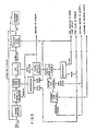
- raw solid municipal and industrial refuse is deposited on the infeed end of a conventional belt conveyor 40 in any suitable fashion.
- truck loads of the refuse may be deposited on a flat receiving surface and pushed by a bulldozer into an open collection hopper (not shown) leading to the infeed end of the conveyor 40.
- the composition of the raw refuse can vary tremendously depending upon such factors as season and locality. The following list of approximate percentages of components by weight is illustrative of the composition of typical municipal refuse:
- the moisture content of the refuse can vary tremendously. Moisture contents as low as 13% by weight and as high as 53% by weight have been measured. Percentages hereafter given refer to percentage by weight, unless otherwise specified. It will be understood that the percentages hereafter given relating to the separation performed by the various components of the apparatus will vary depending upon the composition and moisture content of the refuse.
- Refuse from the discharge end of the conveyor 40 is deposited into a primary shredder 42 where the refuse is reduced to a size suitable for further processing.
- Various types of shredders such as hammermills, may be used. Examples of suitable commercially available shredders are the American Solid Waste Shredders manufactured by American Pulverizer Company, 5540 West Park Avenue, St. Louis, Missouri, 63110 and the Williams Solid Waste Shredders manufactured by Williams Patent Crusher and Pulverizer Company, 2701 North Broadway, St. Louis, Missouri, 63102.
- the primary shredder shreds the refuse into pieces of a range of sizes. Preferably a major portion of these pieces have a maximum dimension of 10,16 cm or less. Much of the glass contained in the raw refuse is crushed in the primary shredder.
- the shredded refuse is discharged from the primary shredder 42 onto a conveyor such as a vibrating pan 44 which conveys the refuse underneath a first magnetic separator 46.
- a conveyor such as a vibrating pan 44 which conveys the refuse underneath a first magnetic separator 46.
- One suitable commercially available vibrating pan is manufactured by Rexnord Incorporated, Material Handling Division, Moson Road, Danville, Kentucky, 40422.
- the first magnetic separator 46 typically extracts from about eigthy-seven to about ninety-two percent of the ferrous metal from the shredded refuse. It is desirable to extract a major portion of the ferrous metal in advance of the disk screens to reduce wear on the same. It also reduces the likelihood that the disk screens will jam or become damaged by pieces of iron or steel.
- Various types of magnetic separators such as the belt or drum types may be used.
- suitable commercially available magnetic separators are the Dings Solid Waste Magnetic System manufactured by the Dings Company, Magnetic Group, 4744 West Electric Avenue, Milwaukie, Wisconsin, 53219 and the Eriez Heavy Duty Magnetic Refuse Drum, manufactured by the Erie Manufacturing Company, Erie, Pennsylvania, 16512.
- the disk screen 10 has an interface opening dimension of approximately 2,54 cm and a slot dimension of approximately 8,25 cm.
- the disk screen 10 typically separates about fifty to sixty percent of the refuse fed thereto into underflow and the remainder into-overflow.
- the overflow is discharged into a secondary shredder 48 which re-shreds the same into the smaller pieces.
- the secondary shredder 48 re-shreds the oversize pieces into pieces which predominantly have a maximum dimension of 5,08 cm or less.
- One of the aforementioned commercially available shredders may be utilized as a secondary shredder.
- the combination of a primary and secondary shredder with an intermediate scalping disk screen is desirable for several reasons. Much of the raw refuse will be reduced to pieces having a maximum dimension of less than 5,08 cm after only a minimal amount of initial shredding time. The work load on the primary shredder is reduced since it does not have to shred the raw refuse for an extended period of time until all of the refuse is reduced to pieces which are less than or equel to the 5,08 cm fuel size. The work load on the secondary shredder is also reduced since it need only re-shred the oversize fraction. Furthermore, if one of the shredders should break down the entire system does not have to shut down since one shredder will still be available, however the operating efficiency of the system will be reduced in such a case. If desired, the secondary shredder 48 can be eliminated and the overflow from the disk screen 10 can be returned by a turntable or other conveyor to the primary shredder for re-shredding.
- the underflow from the disk screen 10 is conveyed to a fine disk screen 12 which has an interface opening dimension of approximately 0,95 cm and a slot dimension of approximately 1,95 cm.
- the fine disk screen 12 typically separates about twelve to sixteen percent of the refuse received thereby into underflow and the remainder into overflow:
- the underflow from the disk screen 12 consists primarily of finely ground glass and ceramic material, and other grit. It also contains some fine fiber.
- the overflow consists of glass fragments and other particles greater than 0,95 cm in dimension.
- the re-shredded refuse from the secondary shredder 48 and the overflow from the fine disk screen 12 are both discharged into a suitable conveyor such as a second vibrating pan 50.
- a suitable conveyor such as a second vibrating pan 50.
- One of the aforementioned commercially available vibrating pans can be utilized.
- the shredded refuse from the vibrating pan 50 is discharged into a metering bin 52 which is designed to feed a constant volume of shredded refuse to an air ensembleifier 54. Without the metering bin the separating efficiency of the air classifier would be greatly reduced.
- One suitable commercially available metering bin is manufactured by the Rader Companies, Inc., 6005 Northeast 82nd Avenue, Portland, Oregon, 97220, and is sold as part of their ADS (Registered Trademark) System. It has a steeply inclined belt conveyor having flights. A leveling roll over the conveyor scalps off excess refuse so that a more or less constant quantity of refuse is carried between the flights to the air classifier 54.
- Shredded refuse from the metering bin 52 is discharged into the star feeder air lock of the air classifier 54.
- the shredded refuse is separated into a light fuel fraction consisting primarily of paper, plastic, miscellaneous light fibrous material, rags, wood, etc. and a heavy fraction consisting primarily of heavier inorganic material, e.g. non-ferrous metal, glass chunks, ground up aluminum cans, heavy fiber, rubber, leather, etc.
- the light fraction typically comprises about eighty to ninety-five percent of the shredded refuse fed to the air classifier 54.
- the apparatus of Fig. 1 typically separates about seventy-five to eighty- two percent of the total amount of raw refuse into a light fuel fraction. Of course, as previously mentioned these percentages can vary greatly depending upon the composition of the shredded refuse and its moisture content.
- air classifiers may be used. However, since precise air control is critical to optimum separation in the air classifier it is preferred to use the air classifier sold as part of the RaderADS System (previously noted).
- This air classifier is described in detail in US-A-4230 559, the disclosure of which is specifically incorporated herein by reference. It has movable, hinged panels which allow for adjustment in both the size and shape of the air separation zone. Air volume and refuse infeed are held constant and the panels are adjusted to control what portion of the refuse drops and what portion flies.
- This air classifier also includes a secondary air bleed-in which improves separation efficiency.
- the light fuel fraction discharged from the air classifier 54 is conveyed to a cyclone 56 which separates the light fraction from the conveying air expelled from the air classifier.
- the light fuel fraction drops to the bottom of the cyclone and is discharged therefrom through a star feeder air lock. It is then conveyed to the power plant boiler.
- the conveying air is discharged from the top of the cyclone 56. It contains a significant quantity of dust and other fine particulate material which is filtered out in a bag house 58.
- a wide variety of commercially available cyclones are suitable, however it is preferable to use the cyclone sold as part of the Rader ADS System previously mentioned. This cyclone has replaceable liners.
- the light fuel fraction which descends to the bottom of this cyclone passes through a vortex straightner in the form of a plurality of radially inwardly extending plates.
- the vortex straightner insures a constant, even, vertical drop of the light fuel fraction.
- the light fuel fraction from the cyclone 56 may be discharged onto a scalping disk screen 20 which separates out oversize pieces which have not heretofore been removed for re-shredding by the secondary shredder 48.
- the scalping disk screen 20 has an interface opening dimension of approximately 2,54 cm and a slot dimension of approximately 8,25 cm. It serves as a final fuel size control.
- the conveying air discharged from the cyclone 56 is preferably drawn through a reverse flow trap 60 with the aid of a fan 62.
- Oversize pieces of refuse which have not heretofore been extracted are removed.
- the reverse flow trap comprises a large cyclinder having an infeed pipe or conduit coupled to its upper end and a laterally extending dust pipe coupled to its side wall. Due to the relatively low velocity of air within the cylinder oversize pieces of refuse settle therein while the dust is carried to the bag house. A screen on the dust pipe prevents oversize pieces of refuse from passing through the dust pipe into the bag house.
- the heavy fraction discharged from the air classifie.r 54 is conveyed underneath a second magnetic separator 64 which extracts substantially all of the remaining ferrous metal. Preferably about ninety-five to ninety-eight percent of the ferrous metal originally contained in the raw refuse has been removed after the second magnetic separator.
- Commercially available magnetic separators of the aforementioned belt or drum type are suitable for this purpose.
- the remaining heavy fraction is now processed through- a triple assembly of the disk screens 14, 16 and 18, in sequence. These disk screens have progressively larger apertures. Initially the remaining heavy fraction is fed to the fine disk screen 14 which has an interface opening dimension of approximately 0,95 cm and a slot dimension of approximately 2,85 cm. This disk screen 14 separates the remaining heavy fraction into an underflow typically consisting of about twenty to thirty percent of the refuse fed thereto. This underflow consists primarily of finely ground glass and ceramic material and other grit which has not been previously removed. This underflow is combined with the underflow of similar composition from the fine disk screen 12 and both are conveyed to a glass processing station (not shown) for recycling to a glass plant. This material may also be used as road aggregate.
- the underflow from the disk screens 12 and 14 may be processed through a special separator 66 designed to separate the glass from the fine fiber.
- a special separator 66 designed to separate the glass from the fine fiber.
- One suitable commercially available separator for this purpose is the CONCENTRATOR manufactured by Kipp Kelly, Ltd., 68 Higgin Avenue, Winnipeg Manitoba, Canada, R3B-OA6.
- This unit includes. a vibrating screen onto which the underflow is discharged. The holes in the screen are too small to permit any of the underflow to pass therethrough. Air is forced upwardly through the holes to separate the fine fiber from the glass.
- the overflow from the fine disk screen 14 is discharged onto the medium disk screen 16. It has an interface opening dimension of approximately 3,80 cm and a slot dimension of approximately 3,80 cm. It separates the remaining refuse fed thereto into an underflow typically consisting of about forty to fifty percent of the refuse fed thereto.
- This underflow consists primarily of poor grade fibrous material and inorganic material. It may be disposed of by using it as landfill or it may be processed through an additional disk screen (not shown) to separate the combusible portion for use as fuel.
- the overflow from the medium disk screen 16 is discharged onto the coarse disk screen 18 which has an interface opening dimension of approximately 7,60 cm and a slot dimension of approximately 8,25 cm.
- the coarse disk screen 18 separates the remaining refuse into an underflow typically consisting of about seventy to eighty percent of the refuse fed thereto. A large proportion of this underflow consists of partially shredded aluminum cans.
- the uriderflow from the disk screen 18 can be conveyed to an aluminum recovery system such as an aluminum magnet (not shown) which will separate a fraction therefrom consisting almost entirely of aluminum cans which can be readily recycled.
- the overflow from the coarse disk screen 18 consists primarily of large chunks of glass, non-ferrous metal, and other miscellaneous pieces of oversized refuse which have not heretofore been removed. This overflow is disposed of by using it as landfill.
- the system of Fig. 1 can be modified in various ways to accommodate specific needs dictated by the composition of the refuse as well as space and capital limitations.
- the interface opening and slot dimensions of the various disk screens can be adjusted-to achieve maximum separating efficiency. This is readily accomplished by changing the sizes of the spacers.
- the disk screens 14, 16 and 18 could be combined into a single unit.
- various subcombinations of the system of Fig. 1 could be utilized alone or in combination with other refuse processing systems to improve separating efficiency. For example, the system of Fig. 1 without the disk screens 14, 16 and 18 would still produce a high quality fuel fraction.
- the use of a fine disk screen for removing finely ground glass and ceramic material from shredded refuse before separating it in an air classifier improves the separating efficiency of the air classifier.
- the use of a scalping disk screen can improve the overall efficiency of the shredding operation in terms of the size of the shredder or shredders required and the energy consumed by the shredding operation.
- the combination of an air classifier with fine, medium, and coarse disk screens for separating the heavy fraction discharged from the air classifier results in highly efficient recovery of resources from the heavy fraction.
- the moisture content of the refuse is relatively high it may be desirable in terms of overall energy efficiency to process the shredded refuse through a dryer. This will raise the Joule content of the fuel fraction. It will also improve the separating efficiency of the various components.
- One suitable commercially available dryer is the Single Pass Rotating Drum Dryer manufactured by the Thompson Dehydrating Company, 700 West Laurent, Topeka Kansas, 66608.
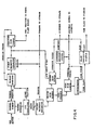
- shredded refuse from a primary shredder is conveyed underneath a first magnetic separator and then discharged onto a first fine disk screen.
- the underflow from the first fine disk screen consists primarily of ground glass and other fine material, e.g. fine fiber.
- This underflow is processed through a special separator designed to separate the glass from the fine fiber.
- One suitable commercially available separator for this purpose is the CONCENTRATOR previously noted.
- the overflow from the first fine disk screen is separated in an air classifier into a light fraction and a heavy fraction.
- the light fraction is discharged onto a scalping disk screen which scalps out oversize pieces for re-shredding by either a secondary shredder or the primary shredder.
- the underflow from the scalping disk screen and the fiber from the CONCENTRATOR are combined to form a fuel fraction.
- the heavy fraction from the air classifier is conveyed under a second magnetic separator to a consecutive assembly of a second fine disk. screen, a medium disk screen, and a coarse disk screen, which perform essentially the same functions as the three disk screens of the apparatus of Fig. 1 which process the heavy fraction of its air classifier,
- the underflow from the second fine disk screen is processed through a second CONCENTRATOR to remove glass and fine fiber not previously removed.
- the fine fiber from the second CONCENTRATOR also becomes part of the fuel fraction.
- the raw refuse is first processed through a trommel screen, the underflow of which consists primarily of glass ' and cans with some loose fiber.
- the overflow of the trommel screen is primarily glass free.
- the trommel screen underflow may be discharged into an air classifier which separates the underflow into a light fraction and a heavy fraction.
- the trommel screen overflow and the light fraction from the air classifier are discharged into a primary shredder.
- Shredded refuse from the primary shredder is passed under a first magnetic separator and then discharged onto a scalping disk screen the underflow of which . forms a fuel fraction.
- the overflow from the scalping disk screen is re-shredded by either a secondary shredder (not shown) or by the primary shredder.
- the heavy fraction from the air classifier is passed under a second magnetic separator and then discharged onto a medium disk screen.
- the underflow from the medium disk screen is conveyed into a twin opposing roll crusher which reduces the larger pieces of glass and fiber into smaller pieces.
- the output from the roll crusher is discharged onto a fine disk screen, the underflow of which consists primarily of ground glass and other fine fibrous material.
- This underflow is processed through a CONCENTRATOR of the aforementioned type. Glass from the CONCENTRATOR is processed in a glass processing station.
- the overflow from the medium disk screen is discharged onto a coarse disk screen. Air is forced upwardly through the coarse disk screen to separate large pieces of fibrous material which are conveyed to the scalping disk screen.
- the underflow from the coarse disk screen consists primarily of aluminum cans which are separated by an aluminum recovery system.
- the overflow from the coarse disk screen, the overflow from the fine disk screen, the fiber from the CONCENTRATOR, and the non-aluminum material from the aluminum recovery system are combined and are disposed of by using the same as landfill.
Landscapes
- Processing Of Solid Wastes (AREA)
- Solid Fuels And Fuel-Associated Substances (AREA)
- Combined Means For Separation Of Solids (AREA)
Claims (14)
Priority Applications (3)
| Application Number | Priority Date | Filing Date | Title |
|---|---|---|---|
| DE8282630036T DE3272686D1 (en) | 1982-05-04 | 1982-05-04 | Method and apparatus for recovering fuel and other resources from refuse utilizing disk screens |
| EP19820630036 EP0093220B1 (fr) | 1982-05-04 | 1982-05-04 | Procédé et installation pour récupérer des combustibles et autres produits dans les déchets en utilisant des tamis à disques |
| AT82630036T ATE21488T1 (de) | 1982-05-04 | 1982-05-04 | Verfahren und vorrichtung zur wiedergewinnung von brennstoff und anderen mitteln aus muell durch verwendung von scheibenrosten. |
Applications Claiming Priority (1)
| Application Number | Priority Date | Filing Date | Title |
|---|---|---|---|
| EP19820630036 EP0093220B1 (fr) | 1982-05-04 | 1982-05-04 | Procédé et installation pour récupérer des combustibles et autres produits dans les déchets en utilisant des tamis à disques |
Publications (2)
| Publication Number | Publication Date |
|---|---|
| EP0093220A1 EP0093220A1 (fr) | 1983-11-09 |
| EP0093220B1 true EP0093220B1 (fr) | 1986-08-20 |
Family
ID=8190006
Family Applications (1)
| Application Number | Title | Priority Date | Filing Date |
|---|---|---|---|
| EP19820630036 Expired EP0093220B1 (fr) | 1982-05-04 | 1982-05-04 | Procédé et installation pour récupérer des combustibles et autres produits dans les déchets en utilisant des tamis à disques |
Country Status (3)
| Country | Link |
|---|---|
| EP (1) | EP0093220B1 (fr) |
| AT (1) | ATE21488T1 (fr) |
| DE (1) | DE3272686D1 (fr) |
Families Citing this family (5)
| Publication number | Priority date | Publication date | Assignee | Title |
|---|---|---|---|---|
| US4846975A (en) * | 1987-11-06 | 1989-07-11 | Beloit Corporation | Anaerobic digestion process |
| US5110454A (en) * | 1988-01-19 | 1992-05-05 | Recovery Systems Technology, Inc. | Apparatus for reclaiming gravel, soil particles and wood pieces from a mixture of the same |
| FR2780320B1 (fr) * | 1998-06-24 | 2001-02-16 | Austruy Christiane | Procede de recyclage, de transformation et d'elimination des dechets menagers et industriels banaux, avec production d'energie a partir d'un combustible fabrique avec les dechets tries |
| DE29813559U1 (de) * | 1998-07-31 | 1998-11-12 | ZEMAG GmbH, 06712 Zeitz | Walzenrostsieb |
| GB2412889B (en) | 2004-05-29 | 2006-06-07 | Fairport Engineering Group Ltd | Biomass material |
Family Cites Families (9)
| Publication number | Priority date | Publication date | Assignee | Title |
|---|---|---|---|---|
| US3848813A (en) * | 1973-03-09 | 1974-11-19 | Us Interior | Continuous process for mechanically separating materials contained in urban refuse |
| NL7317205A (nl) * | 1973-10-11 | 1975-04-15 | American Can Co | Werkwijze ter behandeling van gemeentelijk afval. |
| US4098464A (en) * | 1974-10-18 | 1978-07-04 | Krauss-Maffei Aktiengesellschaft | Method of treating refuse for reclamation of valuable components thereof |
| US4037723A (en) * | 1975-05-02 | 1977-07-26 | Rader Companies, Inc. | Disk separator |
| US4063903A (en) * | 1975-09-08 | 1977-12-20 | Combustion Equipment Associates Inc. | Apparatus for disposal of solid wastes and recovery of fuel product therefrom |
| US4113185A (en) * | 1977-06-08 | 1978-09-12 | Black Clawson Fibreclaim, Inc. | Process for producing fuel from solid waste |
| JPS5490658A (en) * | 1977-09-05 | 1979-07-18 | Peabody Holmes Ltd | Same body sorting method and its device |
| US4230559A (en) * | 1978-11-22 | 1980-10-28 | Rader Companies, Inc. | Apparatus for pneumatically separating fractions of a particulate material |
| US4266676A (en) * | 1979-05-10 | 1981-05-12 | Spm Group, Inc. | Apparatus for separation of material of heterogeneous character |
-
1982
- 1982-05-04 EP EP19820630036 patent/EP0093220B1/fr not_active Expired
- 1982-05-04 DE DE8282630036T patent/DE3272686D1/de not_active Expired
- 1982-05-04 AT AT82630036T patent/ATE21488T1/de active
Also Published As
| Publication number | Publication date |
|---|---|
| EP0093220A1 (fr) | 1983-11-09 |
| DE3272686D1 (en) | 1986-09-25 |
| ATE21488T1 (de) | 1986-09-15 |
Similar Documents
| Publication | Publication Date | Title |
|---|---|---|
| US4341353A (en) | Method and apparatus for recovering fuel and other resources from refuse utilizing disk screens | |
| US4098464A (en) | Method of treating refuse for reclamation of valuable components thereof | |
| US3788568A (en) | Recovery of salvageable components from waste material | |
| US3848813A (en) | Continuous process for mechanically separating materials contained in urban refuse | |
| US4113185A (en) | Process for producing fuel from solid waste | |
| US4070273A (en) | Glass recovery | |
| US3945575A (en) | Recovery of salvageable components from waste materials | |
| US5197398A (en) | Separation of pyrite from coal in a fluidized bed | |
| US5120767A (en) | Process and apparatus for reclaiming the economic components of scrap rubber tires | |
| US5356082A (en) | Incinerated waste material treatment | |
| CA1069084A (fr) | Separateur de dechets a tambour rotatif, incline | |
| KR20130012870A (ko) | 폐차 잔재물의 폴리우레탄 폼 및 섬유 선별 장치 | |
| US5174509A (en) | Incinerated waste material treatment | |
| US20240157368A1 (en) | Process for treating construction and demolition waste material with kinetic pulverization material with kinetic pulverization | |
| EP0093220B1 (fr) | Procédé et installation pour récupérer des combustibles et autres produits dans les déchets en utilisant des tamis à disques | |
| EP0099261A2 (fr) | Traitement des déchets | |
| US7188730B2 (en) | Separation system for single stream compressed recyclables | |
| CA1269355A (fr) | Systeme pour separer les elements metalliques ferreux et non ferreux recuperables contenus dans les dechets d'incineration | |
| Blaschke et al. | FGX air-vibrating separators for cleaning steam coal–functional and economical parameters | |
| DE4442631A1 (de) | Verfahren und Anlage zur Aufbereitung der in Shredderanlagen anfallenden Leichtfraktion | |
| Engdahl | Solid Waste Processing. A State-of-the-Art Report on Unit Operations and Processes. | |
| CN217990049U (zh) | 装修垃圾处理生产线 | |
| SU924974A1 (ru) | Установка дл переработки бытового мусора | |
| JPS5851994Y2 (ja) | 鉄筋コンクリ−トを主体とする廃材の処理再生装置 | |
| Gill et al. | recycling |
Legal Events
| Date | Code | Title | Description |
|---|---|---|---|
| PUAI | Public reference made under article 153(3) epc to a published international application that has entered the european phase |
Free format text: ORIGINAL CODE: 0009012 |
|
| AK | Designated contracting states |
Designated state(s): AT CH DE FR GB IT LI SE |
|
| 17P | Request for examination filed |
Effective date: 19840430 |
|
| GRAA | (expected) grant |
Free format text: ORIGINAL CODE: 0009210 |
|
| AK | Designated contracting states |
Kind code of ref document: B1 Designated state(s): AT CH DE FR GB IT LI SE |
|
| REF | Corresponds to: |
Ref document number: 21488 Country of ref document: AT Date of ref document: 19860915 Kind code of ref document: T |
|
| REF | Corresponds to: |
Ref document number: 3272686 Country of ref document: DE Date of ref document: 19860925 |
|
| ITF | It: translation for a ep patent filed | ||
| ET | Fr: translation filed | ||
| PLBI | Opposition filed |
Free format text: ORIGINAL CODE: 0009260 |
|
| 26 | Opposition filed |
Opponent name: HAZEMAG DR. E. ANDREAS GMBH & CO. Effective date: 19870515 |
|
| RDAG | Patent revoked |
Free format text: ORIGINAL CODE: 0009271 |
|
| STAA | Information on the status of an ep patent application or granted ep patent |
Free format text: STATUS: PATENT REVOKED |
|
| 27W | Patent revoked |
Effective date: 19871212 |
|
| GBPR | Gb: patent revoked under art. 102 of the ep convention designating the uk as contracting state | ||
| REG | Reference to a national code |
Ref country code: CH Ref legal event code: PL |
|
| EUG | Se: european patent has lapsed |
Ref document number: 82630036.0 |